Energy and Power Engineering, 2013, 5, 121-124
doi:10.4236/epe.2013.54B023 Published Online July 2013 (http://www.scirp.org/journal/epe)
Control of Unit Power Factor PWM Rectifier*
Meifang Xue, Mingzhi He
School of Electrical Engineering, Beijing Jiaotong University, Beijing, China
Email: xuemeifang12@gmail.com
Received March, 2013
ABSTRACT
To solve the problem of harmonic pollution to the power grid that caused by traditional diode rectifier and phase con-
trolled rectifier, the unit power factor PWM rectifier is designed. The topology structure of the rectifier circuit is intro-
duced and the double closed-loop control strategy in three-phase stationary coordinate system is analyzed. For the defi-
ciency of control strategy, the control strategy in two-phase synchronous rotating coordinate system is proposed. This
makes the independent control of active current and reactive current to be realized. The simulation model of the PWM
rectifier is built and the effectiveness of the control method proposed in this paper is verified by simulation.
Keywords: Control; PWM Rectifier; Unit Power Factor; d, q Coordinates
1. Introduction
Unity power factor PWM rectifier has the advantages of
high power factor, low harmonic content of grid side
current, energy bidirectional transmission etc, is widely
used in AC drive, reactive power compensation, active
power filter, unified power flow control, as well as unin-
terruptible power supply, etc[1]. This paper introduces
the topology of three-phase PWM rectifier, and describes
the control method of the rectifier in three-phase static
coordinate system. On the basis of the analysis of the
advantages and disadvantages of this control method, the
control method in two-phase synchronous rotating coor-
dinate system is put forward. Then the mathematical
model of three-phase PWM rectifier in d, q coordinates is
established and the single control of active current and
relative current is realized.
2. The Control Method of Three-phase
Voltage Source PWM Rectifier in
Three-phase Static Coordinate System
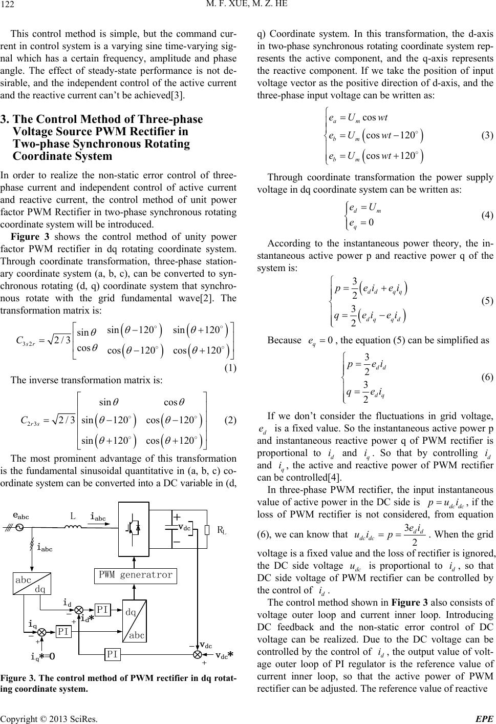
Figure 1 shows the topology of three-phase voltage source
PWM rectifier, abc
is three-phase voltage source, C is
the dc side filtering capacity and
eee
L
R is the load.
In order to realize the control of input current and
output voltage, the traditional method is controlling the
three-phase input current directly. The control of the in-
put current is also the control of the flow of energy, thus
the control of the output voltage can be realized. The
control method of PWM rectifier in the three-phase sta-
tionary coordinate system is shown in Figure 2.
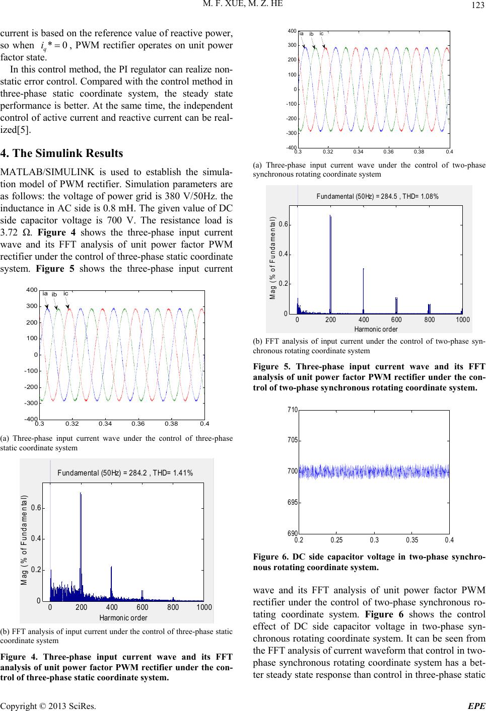
In this control method, the outer loop controls the DC
voltage. The difference value of the command signal and
actual signal of DC side voltage is imported to PI regu-
lator. The output value of PI regulator is DC current sig-
nal m
I
, m
I
is proportional to the amplitude of AC input
current. So the command signal of three-phase AC cur-
rent a*
I
*
b
I
*
c
I
can be obtained by separately
multiplying m
I
by sinusoidal signal whose phase is the
same as three-phase voltage. The difference value of
command current and actual current is imported to PI
regulator, and the sinusoidal modulation wave can be
deserved. By comparing the sinusoidal modulation wave
with carrier wave, the PWM wave which can control the
switch can be deserved.
Figure 1. The topology of three-phase voltage source PWM
rectifier.
sin t
2
sin( )
3
t
2
sin( )
3
t
Figure 2. The control method of PWM rectifier in three-
phase stationary coordinate system.
*Project Supported by National Natural Science Foundation of China
(51207008)
Copyright © 2013 SciRes. EPE
M. F. XUE, M. Z. HE
122
This control method is simple, but the command cur-
rent in control system is a varying sine time-varying sig-
nal which has a certain frequency, amplitude and phase
angle. The effect of steady-state performance is not de-
sirable, and the independent control of the active current
and the reactive current can’t be achieved[3].
3. The Control Method of Three-phase
Voltage Source PWM Rectifier in
Two-phase Synchronous Rotating
Coordinate System
In order to realize the non-static error control of three-
phase current and independent control of active current
and reactive current, the control method of unit power
factor PWM Rectifier in two-phase synchronous rotating
coordinate system will be introduced.
Figure 3 shows the control method of unity power
factor PWM rectifier in dq rotating coordinate system.
Through coordinate transformation, three-phase station-
ary coordinate system (a, b, c), can be converted to syn-
chronous rotating (d, q) coordinate system that synchro-
nous rotate with the grid fundamental wave[2]. The
transformation matrix is:




32
sin120 sin120
sin
2/3 cos cos120 cos120
sr
C










(1)
The inverse transformation matrix is:


23
sin cos
2 / 3sin120cos120
sin120 cos120
rs
C





 



(2)
The most prominent advantage of this transformation
is the fundamental sinusoidal quantitative in (a, b, c) co-
ordinate system can be converted into a DC variable in (d,
Figure 3. The control method of PWM rectifier in dq rotat-
ing coordinate system.
q) Coordinate system. In this transformation, the d-axis
in two-phase synchronous rotating coordinate system rep-
resents the active component, and the q-axis represents
the reactive component. If we take the position of input
voltage vector as the positive direction of d-axis, and the
three-phase input voltage can be written as:

cos
cos 120
cos 120
am
bm
bm
eU wt
eU wt
eU wt


m
(3)
Through coordinate transformation the power supply
voltage in dq coordinate system can be written as:
0
d
q
eU
e
(4)
According to the instantaneous power theory, the in-
stantaneous active power p and reactive power q of the
system is:


3
2
3
2
dd qq
dq qd
peiei
qeiei


(5)
Because 0
q
e
, the equation (5) can be simplified as
3
2
3
2
dd
dq
pei
qei
(6)
If we don’t consider the fluctuations in grid voltage,
d is a fixed value. So the instantaneous active power p
and instantaneous reactive power q of PWM rectifier is
proportional to d and q. So that by controlling d
and q, the active and reactive power of PWM rectifier
can be controlled[4].
e
i ii
i
In three-phase PWM rectifier, the input instantaneous
value of active power in the DC side is dcdc , if the
loss of PWM rectifier is not considered, from equation
pui
(6), we can know that 3
2
dd
dc dc
ei
ui p . When the grid
voltage is a fixed value and the loss of rectifier is ignored,
the DC side voltage dc is proportional to d, so that
DC side voltage of PWM rectifier can be controlled by
the control of .
u i
d
The control method shown in Figure 3 also consists of
voltage outer loop and current inner loop. Introducing
DC feedback and the non-static error control of DC
voltage can be realized. Due to the DC voltage can be
controlled by the control of d, the output value of volt-
age outer loop of PI regulator is the reference value of
current inner loop, so that the active power of PWM
rectifier can be adjusted. The reference value of reactive
i
i
Copyright © 2013 SciRes. EPE
M. F. XUE, M. Z. HE 123
current is based on the reference value of reactive power,
so when , PWM rectifier operates on unit power
factor state.
*0
q
i
In this control method, the PI regulator can realize non-
static error control. Compared with the control method in
three-phase static coordinate system, the steady state
performance is better. At the same time, the independent
control of active current and reactive current can be real-
ized[5].
4. The Simulink Results
MATLAB/SIMULINK is used to establish the simula-
tion model of PWM rectifier. Simulation parameters are
as follows: the voltage of power grid is 380 V/50Hz. the
inductance in AC side is 0.8 mH. The given value of DC
side capacitor voltage is 700 V. The resistance load is
3.72 . Figure 4 shows the three-phase input current
wave and its FFT analysis of unit power factor PWM
rectifier under the control of three-phase static coordinate
system. Figure 5 shows the three-phase input current
0.30.320.34 0.36 0.380.4
-400
-300
-200
-100
0
100
200
300
400 ia ib ic
(a) Three-phase input current wave under the control of three-phase
static coordinate system
0200 400 6008001000
0
0.2
0.4
0.6
Harmonic order
Fundamental (50Hz) = 284.2 , THD= 1.41%
Mag (% of Fundamental)
(b) FFT analysis of input current under the control of three-phase static
coordinate system
Figure 4. Three-phase input current wave and its FFT
analysis of unit power factor PWM rectifier under the con-
trol of three-phase static coordinate system.
0.30.32 0.340.36 0.380.4
-400
-300
-200
-100
0
100
200
300
400 ib icia
(a) Three-phase input current wave under the control of two-phase
synchronous rotating coordinate system
0200400 6008001000
0
0.2
0.4
0.6
Harm onic order
Fundamental (50Hz) = 284.5 , THD= 1.08%
Mag (% of Fundamental)
(b) FFT analysis of input current under the control of two-phase syn-
chronous rotating coordinate system
Figure 5. Three-phase input current wave and its FFT
analysis of unit power factor PWM rectifier under the con-
trol of two-phase synchronous rotating coordinate system.
0.20.250.30.350.4
690
695
700
705
710
Figure 6. DC side capacitor voltage in two-phase synchro-
nous rotating coordinate system.
wave and its FFT analysis of unit power factor PWM
rectifier under the control of two-phase synchronous ro-
tating coordinate system. Figure 6 shows the control
effect of DC side capacitor voltage in two-phase syn-
chronous rotating coordinate system. It can be seen from
the FFT analysis of current waveform that control in two-
phase synchronous rotating coordinate system has a bet-
ter steady state response than control in three-phase static
Copyright © 2013 SciRes. EPE
M. F. XUE, M. Z. HE
Copyright © 2013 SciRes. EPE
124
coordinate system.
5. Conclusions
This paper respectively introduced the control strategy of
unit power factor PWM rectifier in three-phase static
coordinate system and two-phase rotating coordinate
system, and the two control method are compared. The-
oretical analysis and simulation results show that the
control in synchronous rotating coordinate system has
better steady state performance.
REFERENCES
[1] K.-N. Areerak, S. V. Bozhko, G. M. Asher and D. W. P.
Thomas, “DQ-Transformation Approach for Modelling
and Stability Analysis of AC-DC Power System with
Controlled PWM Rectifier and Constant Power Loads,”
International Power Electronics and Motion Control
Conference, 2008, pp. 2049-2054.
[2] Z. Zheng, C. Wang and X. P. Jing, “Comparison of Two
Control Strategy for Three-Phase Voltage Source PWM
Rectifier,” International Conference on Computer and
Communication Technologies in Agriculture Engineering,
2010, pp. 101-104.
doi:10.1109/CCTAE.2010.5544851
[3] K. Wei and F. Xiao, “The Improvement of Current
Feed-forward Control Strategy on Voltage Source PWM
Rectifier,” International Symposium on Computational
Intelligence and Design, 2010, pp. 107-109.
[4] S. R. Naidu, D. A. Fernandes and K. P. Medeiros, “Sim-
plified Control of a Three-phase PWM Rectifier,” Pro-
ceedings of the 2011 International Conference on Power
Engineering, Energy and Electrical Drives, Torremolinos
(Málaga), Spain, May 2011, pp. 2758-2761.
[5] J. G. Zhang, B. Yang, G. Zeng and Y. Y. Tian, “A Unity
Power Factor Control Method of PWM Rectifier,” Power
and Energy Engineering Conference (APPEEC),
Asia-Pacific, 2012, pp. 1-4.