Energy and Power Engineering, 2013, 5, 109-115
doi:10.4236/epe.2013.54B021 Published Online July 2013 (http://www.scirp.org/journal/epe)
Analysis of Thermal Conductivity of Frost on Cryogenic
Finned-tube Vaporizer Using Fractal Method
Shuping Chen, Shuting Yao, Fushou Xie
School of Petrochemical Engineering, Lanzhou University of Technology, Lanzhou, China
Email: chensp@lut.cn
Received March, 2013
ABSTRACT
Thermal conductivity of frost is not only related to density, but also affected by its microstructure and environmental
conditions, and it will continuously change with the formation and growth of frost. Images of frost formation and
growth on the cryogenic surface in various shapes at different stages were obtained by experimental measurements, and
a numerical simulation of frost formation and growth was carried out based on Diffusion Limited Aggregation (DLA)
model of fractal theory in this paper. Based on the frost structure obtained by experiment, the fractal dimension of pore
area distribution and porosity of frost layer on the cryogenic finned-tube vaporizer were calculated by using fractal me-
thod, and combined with heat conduction model of frost layer obtained by thermal resistance method, the thermal con-
ductivity of frost on the cryogenic surface was calculated. The result shows that the thermal conductivity calculated by
the fractal model coincides with the range of the experimental data. Additionally, comparison with other heat conduc-
tion models indicated that it is feasible to introduce the fractal dimension of pore area distribution into heat conduction
model to deduce the thermal conductivity of frost.
Keywords: Cryogenic Finned-tube Vaporizer; Thermal Conductivity; Frost Layer; Fractal
1. Introduction
Finned-tube vaporizer will be frosted once its surface
temperature is below the dew point of surrounding humid
air, and lower than 0. The frost on the surface of va-
porizer will decrease the efficiency of vaporizer, increase
the pressure loss and even result in the failure of the va-
porizer system. Sublimation frosting of humid air on the
vaporizer surface involves heat transfer, mass transfer
and the boundary movement of special porous medium.
Of all the issues concerning the sublimation frosting,
frost physical properties especially the thermal conduc-
tivity is one of the key parameters. There have been a lot
of researches on the effect of thermal conductivity on
frosting problem. At the beginning, researchers mainly
concentrated on the experimental study of the formation
and growth of frost on the simple geometric surfaces,
such as level plate, pipe and vertical plate. Various em-
pirical or semi-empirical correlations of the density and
thermal conductivity were proposed [1-7]. Then, numer-
ous attempts on the growth and physical properties of
frost on the cold plate or pipe based on the mechanism of
frosting were made, too. Based on the mechanism of
frosting, and considering the process of water vapor dif-
fusion in frost, Brain [8] firstly put forward that water
vapor flowing into the frost was divided into two parts,
one part was used to increase the thickness of frost, the
other part to increase the density of frost. Hayashi Y [9]
believed that the change of density essentially depended
on the surface temperature of frost which was changing
frequently in the process of frosting. According to the
different structures at different growth and formation
stages of frost, he demonstrated three periods which
could describe the evolution of frost layer: the crystal
growth period, the frost layer growth period, and the frost
full-growth period, and finally proposed the well-known
correlation for frost density in terms of frost temperature
and ice-air mixture model. On the basis of the theory of
Hayashi Y, considering the space distribution and
time-varying of density and temperature of frost, Tao Y
X [10] applied the control volume average method of
porous medium into ice-air mixture model and improved
the accuracy of the model. Le Call R [11] modified the
boundary conditions and the permeability coefficient of
water vapor in Tao Y X model, and focused on the effec-
tive diffusion coefficient of water vapor, then, he got the
distribution of density, temperature, thermal conductivity
in frost. Chen H [12] further modified Tao Y X model,
and set up a mathematic model of dynamic growth char-
acteristics of frost on a flat plate.
In these researches, the frost was considered as a vir-
tual continuous medium which was distributed uniformly
on a large scale, that is, the volume averaging theory was
Copyright © 2013 SciRes. EPE
S. P. CHEN ET AL.
110
used to describe the geometric distribution of frost.
However, as a porous medium, the thermal conductivity
of frost is not only related to density, but also affected by
its microstructure and the environmental conditions. The
thermal conductivity will continuously change with the
formation and growth of frost, therefore, the thermal
conductivity is a function of density, porosity, tortuosity
and other parameters. The over-simplified frosting model
will result in a serious error. The formation and growth
of frost is a complicated process, therefore, it is very dif-
ficult to obtain an equation of thermal conductivity based
on a theory. Based on simulating the frost crystal struc-
ture which has fractal growth characteristics, Cai L [13]
set up an equilibrium equation at each node and predicted
the thermal conductivity of frost by using the DLA mod-
el. In the present paper, on the basis of the previous work,
according to the experimental observation of frost forma-
tion and growth, the physical process of frost growth was
simulated by DLA (Diffusion Limited Aggregation)
model of fractal theory. The box counting dimension
method was used to determine the fractal dimension of
pore area distribution and fractal porosity of frost profile.
Thereby, a fractal model of heat conduction in frost layer
was established theoretically to determine the effective
thermal conductivity.
2. Frost Formation and Growth Process
The experimental facility utilized in this work is shown
in Figure 1. The facility is composed of the feeding liq-
uid system, the vertical frosting surface, the image acqui-
sition system and the data acquisition system. This ex-
periment is conducted under the conditions of ambient
temperature T = 16.3, humidity RH = 55%, and these
environmental parameters remain unchanged during the
experiment. As shown in Figure 1, liquid nitrogen flows
from the liquid nitrogen tank, then through the vacuum
thermal insulating tube to cryogenic vessel. The vacuum
thermal insulating tube minimizes the loss of refrigera-
tion capacity before liquid nitrogen flowing into the
cryogenic vessel. Cryogenic vessel is welded by alumi-
num flat plates, wrapped with the polyurethane foam
material around it as the thermal insulation layer. A boss
(with length of 120 mm, width of 100 mm, the height of
100 mm) is extended into the cryogenic vessel, and a
vertical flat plate (with length of 120 mm, width of 100
mm) in the boss for frosting. Tubing is installed in the
bottom of cryogenic vessel for connecting the cryogenic
vessel and a glass level gauge, which is used to measure
the height of the liquid nitrogen in the cryogenic vessel.
Liquid nitrogen in cryogenic vessel absorbs heat by con-
vection between the vertical flat plate and indoor humid
air, and then gasifies; humid air will form frost on the
surface of vertical flat plate.
Figure 2 shows the experimental images of frost
growth on the cryogenic surface (with cryogenic surface
temperature Tw= 120) at different time, it can be seen
from (a) and (b) that many dendritic frost crystals formed
on the cryogenic surface, and new dendritic crystals
produced with increasing time; as shown in (c), these
dendritic frost crystals are characterized with fractal
self-similarity to some extent [14, 15].
Figure 3 shows the simulated image of frosting on the
cryogenic surface of finned-tube vaporizer in MATLAB
based on the DLA model of fractal theory. The detailed
algorithm of simulating frosting and simulation results
have been reported previously [16].
Figure 1. Experimental apparatus for frosting test..
Figure 2. Experimental images of frosting on the cryogenic
surface.
Figure 3. Frosting simulated image on the cryogenic surface
of finned-tube vaporizer.
Copyright © 2013 SciRes. EPE
S. P. CHEN ET AL. 111
3. Fractal Characteristics of Frost Layer
3.1. Fractal Dimension
Taking irregular geometric shape as the research object,
fractal geometry is put forward to describe irregular
shape with self-similarity. The so-called fractal is the
geometric object which has self-similarity in shape and
structure, the mathematical expression of fractal is given
by
N(δ)δd (1)
Here, N is occupation space of a fractal object (the line,
the area or volume), δ is measurement scale, and d is
fractal dimension, it may be an integer or not an integer.
Fractal dimension is the measurement of the complexity
of fractal object, a quantitative parameter describing
fractal characteristics of an object. The larger value is,
the more complex the fractal object is. For a fractal area
with d between 1 and 2, its value can be determined by
the slope of curve in figure lnN(δ)-lnδ [17]. Fractal
structure is actually an ideal model and is an abstract of
many complex objects in nature. The true object in na-
ture is closer to random fractal, that is, random fractal
has self-similarity only in a certain scale range, called
statistical self-similarity. For example, the self-similarity
of porous medium is valid just in a certain scale.
Statistical self-similarity is usually called local fractal.
It has been proved that effective thermal physical pa-
rameter E of porous medium is not only related to the
medium’s property of its composition, but also depended
on the space structure of porous medium. According to
local fractal theory, if a porous medium has fractal struc-
ture and local fractal scale l, the effective thermal physi-
cal parameter of porous medium can be expressed as
(,,,
i
Ef dl
E
) (2)
where Ei is thermal physical parameter of each phase
composed of porous medium, ε is average volume poros-
ity of porous medium, d is fractal dimension. This for-
mula is the basic equation of determining thermal physi-
cal parameter of fractal object based on the fractal the-
ory.
Frosting is a transient process accompanied by air-
solid phase change, related with heat transfer, mass
transfer, and the boundary movement of porous medium.
Frost layer may be considered as a random porous me-
dium consisting of ice and air, just as shown in Figure 2.
Ice crystals skeleton of frost layer or pore is not uni-
formly distributed on the profile surface, as it is hard to
fill the entire profile of frost layer. In many cases, the
area distribution of pore structure or ice crystals skeleton
has fractal characteristics, therefore, the corresponding
fractal dimension of area distribution for pore or ice
crystals skeleton can be calculated. The specific calcula-
tion procedures are as follows:
1) As shown in Figure 4, taking any different meas-
urement values X in DA interval.
2) Taking a point as the center of calculated area in
frost layer profile, the box with sides X is used for meas-
uring the area of pore in the calculated profile.
3) Repeat step (2) many times, until the whole frost
layer profile is measured with equal probability, and the
average value of pore area is S.
4) Change scale value X, and repeat the step (2) and
step (3), then a series of pore areas Si corresponding with
different scales Xi can be obtained.
5) Using the least square method for linear fitting, the
S-X logarithm coordinates figure can be obtained.
It is clear that the average value S of pore area of frost
on the cryogenic surface and measurement scale X fit a
linearity in the S-X logarithm coordinates figure, and also
has the following linear relation:
LnS = lnk+dlnX (3)
where k is a proportional constant, the slope d is the
fractal dimension of pore area distribution of frost layer.
3.2. Fractal Porosity of Frost Layer
For frost structure with certain porosity, as the pore area
distribution of frost profile has fractal characteristics, the
Equation (3) can be rearranged to:
d
Sk
X
(4)
where d is fractal dimension of pore area distribution and
S is a measured average value.
By simplifying the actual irregular structure of frost
and assuming that the pore structure of frost as a cube,
where there is the cavity for air flowing through in the
middle of the cubical structure of frost, the rest of the
cubical structure is considered as frost ice crystals skele-
ton. Each calculation volume unit of frost layer is shown
in Figure 5. Since the similar structure has an invariant
property of scale, the heat transfer characteristics of
every calculation volume unit of frost layer will keep in
agreement with the whole frost crystal. Then the effec-
tive volume porosity of frost based on the fractal theory
is defined as:
Figure 4. Schematic diagram of measurement scales.
Copyright © 2013 SciRes. EPE
S. P. CHEN ET AL.
112
Figure 5. Model of volume unit of frost layer.
2
3
2
()
S
X
(5)
Substituting Equation (4) and Equation (5), then:
(1 )
aice

 (6)
The density of frost based on the fractal porosity can
be obtained by the reference [18]:
3
3(2)
2
2
d
k
X
(7)
where ρ is frost density, kg·m-3; ρa is air density, ρa
=1.292 kg·m-3; ρice is ice density, ρice =0.9×10³ kg·m-3.
3.3. Thermal Conductivity of Frost
As a special porous medium, the actual microstructure of
frost is changeable and irregular. The local area fractal,
however, still exists from the above analyses. Therefore,
a simplified unit pore profile model of frost layer shown
in Figure 6. The simplified profile has the same pore
area and the same fractal dimension d of local pore area
with the original actual profile, and then they should
have the same effective thermal properties. For simplify-
ing the calculation, the simplified fractal model of heat
conduction in frost layer shown in Figure 7 is adopted.
The thermal resistance R of the fractal model is shown
in Figure 8 and expressed as:
12
12
(
ii a
ii a
RR R
R
RR R


)
(8)
where
1
3
12
3
1
(1 )
i
i
R

(9)
11
33
22
3
(1 )
(1 )
i
i
R

(10)
2
3
1
a
a
R
(11)
12
3
222
33
(1 )(1)
(1 )
ai
ia
ai
RR
Then
12
2
1
33
3
212 2
2
2
3333
(1 )(1 )
(1 )
(1) (1)()(1 )
ia
a
ai
R

 
 

(13)
The effective thermal conductivity of frost can be ex-
pressed as:
212 2
2
2
333 3
12
2
1
33
3
(1) (1) ()(1 )
1
(1 )(1 )
(1 )
a
ai
ia
R
 



 
(14)
where λa is the thermal conductivity of air, λa=0.024
W·m-1·K-1; λi is the thermal conductivity of ice, λi=1.88
W·m-1·K-1;
λ
is the thermal conductivity of frost.
4. Results and Discussion
4.1. Discussion of Fractal Dimension
The box counting dimension method is used to calculate
the fractal dimension d of pore area distribution of frost
for frosting simulation image shown in Figure 3, and
then being compared with the fractal dimension of ex-
perimental binary image shown in Figure 9. The calcula-
tion result is shown in Figure 10. The fractal dimension
Figure 6. Schematic diagram of an unit pore profile.
Figure 7. Simplified heat conduction mode l of fr ost laye r.
3
 

  


(12)
Figure 8. The schematic d iagram of tota l therm al resist ance.
Copyright © 2013 SciRes. EPE
S. P. CHEN ET AL. 113
Figure 9. Experimental frosting binary image on the
cryogenic surface of finned-tube vaporizer.
Figure 10. Linear fitting for the fractal dimension of pore
area distribution.
of pore area distribution by simulation of frost is d1 =
1.743, and the fractal dimension of pore area distribution
from experimental frost is d2 = 1.466. It can be seen from
Figure 10 that the profile pore distribution of frost on the
surface of finned-tube vaporizer satisfies statistical
self-similarity in measurement scale D~A interval,
namely, the pore distribution of frost profile presents
fractal characteristics. In addition, the consistent of the
fractal dimension of the simulation image d1 with that of
the experimental image d2 shows the rationality of the
numerical simulation and provides a powerful evidence
for further deriving the fractal model of heat conduction
in frost layer.
4.2. Thermal Conductivity of Frost Layer
It can be obtained that the diameter scale of pore space of
the actual frost layer is 1~20. In order to establish a gen-
eral fractal model of frost, a range of 1~20 is used as the
value of measurement scale X in Figure 10. As shown in
Figure 10, d1 = 1.743, k1 = 1.274, d2 = 1.466, k2 = 1.861,
substituting the related values into Equation (7), the den-
sity ρ of the actual frost can be calculated, as shown in
Figure 11. Then the thermal conductivity of actual frost
is got by Equation (14), shown in Figure 12. It can be
seen that the thermal conductivity of actual frost calcu-
lated by the above fractal model agrees well with the
range of 0.020.16 W·m-1·K-1 of the thermal conduc-
tivity reported by reference, and thus explains the ration-
ality of the fractal model of heat conduction.
Figure 13 shows comparison between the proposed
model and other models. It has been generally accepted
that the thermal conductivity of frost is considered to be
depended on density. In fact, there are large differences
0.10.20.30.40.50.60.70.80.9
100
200
300
400
500
600
700
800
Density ρ(k g ·m-3)
Porosity
Figure 11. Density varied with the change of porosity.
100 200 300 400 500 600 700 800
0.0945
0.0950
0.0955
0.0960
0.0965
0.0970
Thermal conductivity λ(W·m-1·K
-1)
Density ρ (Kg· m-3)
Figure 12. Frost layer thermal conductivity varied with
the change of density.
Figure 13. Comparison between the models.
Copyright © 2013 SciRes. EPE
S. P. CHEN ET AL.
114
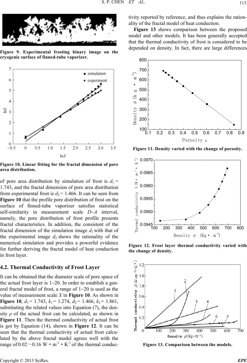
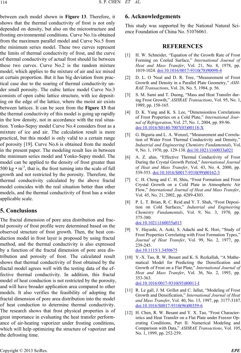
between each model shown in Figure 13. Therefore, it
shows that the thermal conductivity of frost is not only
depended on density, but also on the microstructure and
frosting environmental conditions. Curve No.1is obtained
from the maximum parallel model and Curve No.5 from
the minimum series model. These two curves represent
the limits of thermal conductivity of frost, and the curve
of thermal conductivity of actual frost should lie between
these two curves. Curve No.2 is the random mixture
model, which applies to the mixture of air and ice mixed
at certain proportion. But it has big deviation from prac-
tical case due to the soaring of thermal conductivity un-
der small porosity. The cubic lattice model Curve No.3
consists of open cubic lattice structure, with ice deposit-
ing on the edge of the lattice, where the moist air exists
between lattices. It can be seen from the Figure 13 that
the thermal conductivity of this model is going up rapidly
in the low density, not in accordance with the real situa-
tion. Yonko-Sepsy model Curve No.4 considers frost as a
mixture of ice and air. The calculation result is more
practical, but this model is only valid to a certain range
of porosity [19]. Curve No.6 is obtained from the model
in the present paper. The modeling result lies in between
the minimum series model and Yonko-Sepsy model. The
model can be applied to the density of frost greater than
500 kg·m-3, that is, the frost turning into the scale of full
growth and not restricted by the porosity. Therefore, the
thermal conductivity calculated by the above fractal
model coincides with the real situation better than other
models, and the thermal conductivity of frost has a wider
applicable scale.
5. Conclusions
The fractal dimension of pore area distribution and frac-
tal porosity of frost profile were determined based on the
observed structure of frost growth. Then, the heat con-
duction model in frost layer is proposed by using fractal
method, and the thermal conductivity is also expressed
by a function of the fractal dimension of pore area dis-
tribution and porosity of frost. The calculated result
shows that thermal conductivity of frost obtained by the
fractal model agrees well with the testing data of the ef-
fective thermal conductivity. In addition, this fractal
model of heat conduction is not restricted by the porosity,
and will have broader application area compared to other
models. It also verifies the feasibility of adopting the
fractal dimension of pore area distribution into the model
of heat conduction to determine thermal conductivity.
The research shows that frost physical properties is of
great importance in evaluating the heat transfer perform-
ance of air-heating vaporizer under frosting conditions,
which will help optimizing the structure of vaporizer and
the defrosting time.
6. Acknowledgements
This study was supported by the National Natural Sci-
ence Foundation of China No. 51076061.
REFERENCES
[1] H. W. Schneider, “Equation of the Growth Rate of Frost
Forming on Cooled Surface,” International Journal of
Heat and Mass Transfer, Vol. 21, No. 8, 1978, pp.
1019-1024. doi:10.1016/0017-9310(78)90098-4
[2] D. L. O 'Neal and D. R. Tree, “Measurement of Frost
Growth and Density in a Parallel Plate Geometry,” ASH-
RAE Transactions, Vol. 26, No. 5, 1984, p. 56.
[3] S. M. Sami and T. Duong, “Mass and Heat Transfer dur-
ing Frost Growth,” ASHRAE Transactions, Vol. 95, No. 1,
1989, pp. 158-165.
[4] D. K. Yang and K. S. Lee, “Dimensionless Correlations
of Frost Properties on a Cold Plate,” International Jour-
nal of Refrigeration, Vol. 27, No. 1, 2004, pp. 89-96.
doi:10.1016/S0140-7007(03)00118-X
[5] G. Biguria and L. A. Wenzel, “Measurement and Correla-
tion of Water Frost Thermal Conductivity and Density,”
Industrial and Engineering Chemistry Fundamentals, Vol.
9, No. 1, 1970, pp. 129-138. doi:10.1021/i160033a021
[6] A. Z. ahin, “Effective Thermal Conductivity of Frost
During the Crystal Growth Period,” International Journal
of Heat and Mass Transfer, Vol. 43, No. 4, 2000, pp.
539-553. doi:10.1016/S0017-9310(99)00162-3
[7] C. H. Cheng and C. H. Shiu, “Frost Formation and Frost
Crystal Growth on a Cold Plate in Atmospheric Air
Flow,” International Journal of Heat and Mass Transfer,
Vol. 45, No. 21, 2002, pp. 4289-4303.
[8] P. L. T. Brian, R. C. Reid and Y. T. Shah, “Frost Deposi-
tion on Cold Surfaces,” Industrial and Engineering
Chemistry Fundamentals, Vol. 9, No. 3, 1970, pp.
375-380.
doi:10.1021/i160035a013
[9] Y. Hayashi, A. Aoki, S. Adachi and K. Hori, “Study of
Frost Properties Correlating with Frost Formation Types,”
Journal of Heat Transfer, Vol. 99, No. 2, 1977, pp.
239-245.
doi:10.1115/1.3450675
[10] Y.-X. Tao, R. W. Besant and K. S. Rezkallah, “A Mathe-
matical Model for Predicting the Densification and
Growth of Frost on a Flat Plate,” International Journal of
Heat and Mass Transfer, Vol. 36, No. 2, 1993, pp.
353-363.
doi:10.1016/0017-9310(93)80011-I
[11] R. Le gall, J. M. Grillot and C. Jallut, “Modeling of Frost
Growth and Densification,” International Journal of Heat
and Mass Transfer, Vol. 40, No. 13, 1997, pp. 3177-3187.
doi:10.1016/S0017-9310(96)00359-6
[12] H. Chen, R. W. Besant and Y. X. Tao, “Frost Character-
istics and Heat Transfer on a Flat Plate under Freezer Op-
erating Conditions, Part II: Numerical Modeling and
Comparison with Data,” ASHRAE Transactions, Vol. 105,
No. 1, 1999, pp. 252-259.
Copyright © 2013 SciRes. EPE
S. P. CHEN ET AL.
Copyright © 2013 SciRes. EPE
115
[13] L. Cai, R. H. Wang, P. X. Hou and X. S. Zhang, “Com-
puter Simulation of Frost Growth and Computation of Its
Thermal Conductivity,” Chinese Journal of Chemical
Engineering, Vol. 60, No. 5, 2009, pp. 1111-1115.
[14] Y. L. Hao, I. Jose and X. T. Yong, “Experimental Study
of Initial State of Frost Formation on Flat Surface,” Jour-
nal of Southeast University, Vol. 35, No. 1, 2005, pp.
149-153.
[15] P. X. Hou, L. Cai and W. P. Yu, “Experimental Study and
Fractal Analysis of Ice Crystal Structure at Initial Period
of Frost Formation,” Journal of Applied Sciences, Vol. 25,
No. 2, 2007, pp.193-197.
[16] S. P. Chen, S. T. Yao, F. S. Xie, Z. X. Chang and H. Y.
Han, “Frost Model and Numerical Simulation of
Air-heating Fin-tube Vaporizer,” Cryogenics & Super-
conductivity, Vol. 39, No. 11, 2011, pp. 64-67.
[17] K. Falconer, “Fractal Geometry Mathematical Founda-
tions and Applications,” W.Q. Zeng, Transactions, Sec-
ond edition, Posts &Telecom Press, Beijing, 2007, pp.
270-275.
[18] B. Na, “Analysis of Frost Formation in an Evaporator,”
ph.D. Thesis, Pennsylvania State University, 2003.
[19] J. D. Yonko and C. F. Sepsy, “An Investigation of the
Thermal Conductivity of Frost while Forming on a Flat
Horizontal Plate,” ASHRAE Transactions, Vol. 73, No. 2,
1967, pp. 1.1-1.11.