Paper Menu >>
Journal Menu >>
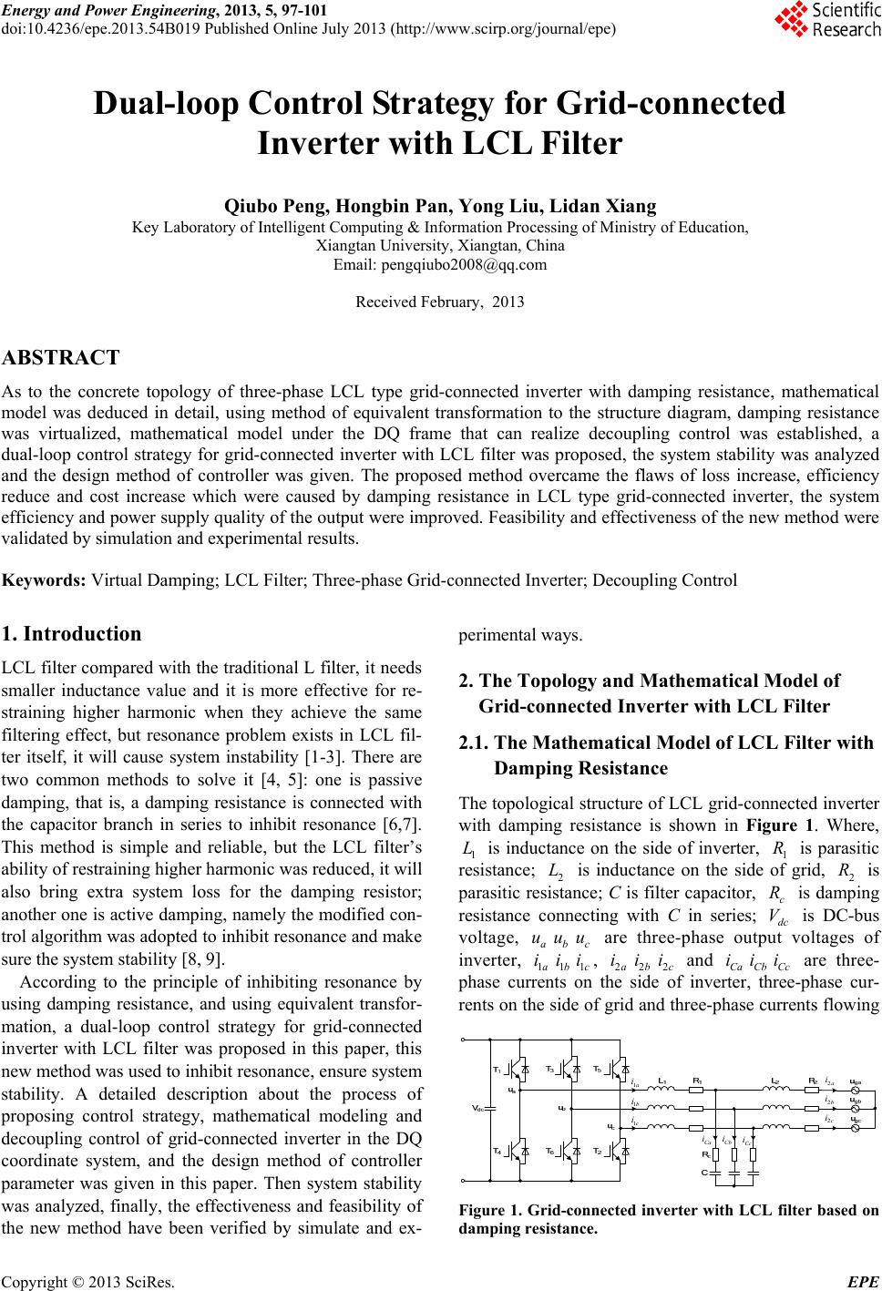 Energy and Power Engineering, 2013, 5, 97-101 doi:10.4236/epe.2013.54B019 Published Online July 2013 (http://www.scirp.org/journal/epe) Dual-loop Control Strategy for Grid-connected Inverter with LCL Filter Qiubo Peng, Hongbin Pan, Yong Liu, Lidan Xiang Key Laboratory of Intelligent Computing & Information Processing of Ministry of Education, Xiangtan University, Xiangtan, China Email: pengqiubo2008@qq.com Received February, 2013 ABSTRACT As to the concrete topology of three-phase LCL type grid-connected inverter with damping resistance, mathematical model was deduced in detail, using method of equivalent transformation to the structure diagram, damping resistance was virtualized, mathematical model under the DQ frame that can realize decoupling control was established, a dual-loop control strategy for grid-connected inverter with LCL filter was proposed, the system stability was analyzed and the design method of controller was given. The proposed method overcame the flaws of loss increase, efficiency reduce and cost increase which were caused by damping resistance in LCL type grid-connected inverter, the system efficiency and power supply quality of the output were improved. Feasibility and effectiveness of the new method were validated by simulation and experimental results. Keywords: Virtual Damping; LCL Filter; Three-phase Grid-connected Inverter; Decoupling Control 1. Introduction LCL filter compared with the traditional L filter, it needs smaller inductance value and it is more effective for re- straining higher harmonic when they achieve the same filtering effect, but resonance problem exists in LCL fil- ter itself, it will cause system instability [1-3]. There are two common methods to solve it [4, 5]: one is passive damping, that is, a damping resistance is connected with the capacitor branch in series to inhibit resonance [6,7]. This method is simple and reliable, but the LCL filter’s ability of restraining higher harmonic was reduced, it will also bring extra system loss for the damping resistor; another one is active damping, namely the modified con- trol algorithm was adopted to inhibit resonance and make sure the system stability [8, 9]. According to the principle of inhibiting resonance by using damping resistance, and using equivalent transfor- mation, a dual-loop control strategy for grid-connected inverter with LCL filter was proposed in this paper, this new method was used to inhibit resonance, ensure system stability. A detailed description about the process of proposing control strategy, mathematical modeling and decoupling control of grid-connected inverter in the DQ coordinate system, and the design method of controller parameter was given in this paper. Then system stability was analyzed, finally, the effectiveness and feasibility of the new method have been verified by simulate and ex- perimental ways. 2. The Topology and Mathematical Model of Grid-connected Inverter with LCL Filter 2.1. The Mathematical Model of LCL Filter with Damping Resistance The topological structure of LCL grid-connected inverter with damping resistance is shown in Figure 1. Where, 1 is inductance on the side of inverter, 1 is parasitic resistance; 2 is inductance on the side of grid, 2 is parasitic resistance; C is filter capacitor, is damping resistance connecting with C in series; dc is DC-bus voltage, are three-phase output voltages of inverter, 1a1b1c, 2a2b2c and Ca Cb Cc are three- phase currents on the side of inverter, three-phase cur- rents on the side of grid and three-phase currents flowing L R c R V i L a b u i R u ic u ii i ii i 1a i 2a i Ca i 1 b i 1 c i Cb i Cc i 2b i 2c i Figure 1. Grid-connected inverter with LCL filter based on damping resistance. Copyright © 2013 SciRes. EPE 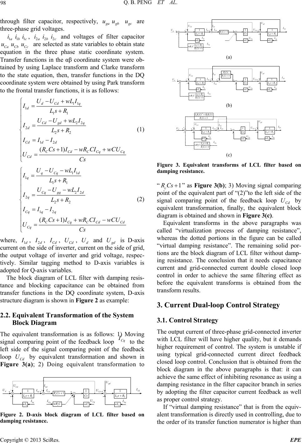 Q. B. PENG ET AL. 98 through filter capacitor, respectively, g a u g b u g c u are three-phase grid voltages. 1a iu1b i1c i u, 2a2b2c and voltages of filter capacitor Ca Cb Cc are selected as state variables to obtain state equation in the three phase static coordinate system. Transfer functions in the αβ coordinate system were ob- tained by using Laplace transform and Clarke transform to the state equation, then, transfer functions in the DQ coordinate system were obtained by using Park transform to the frontal transfer functions, it is as follows: i i i u 11 1 11 22 2 22 12 (1) dCd q d Cd gdq d Cdd d CCdCCq Cd UU wLI ILs R UUwLI ILs R III R CsIwR CIwCU UCs Cq (1) 11 1 11 22 2 22 12 (1) qCq d q Cq gqd q Cqq q CCqCCd Cq UU wLI ILs R UUwLI ILs R III R CsIwR CIwCU UCs Cd (2) where, 1d I , 2d I , Cd I , Cd , d and U U g d U is D-axis current on the side of inverter, current on the side of grid, the output voltage of inverter and grid voltage, respec- tively. Similar tagging method to D-axis variables is adopted for Q-axis variables. The block diagram of LCL filter with damping resis- tance and blocking capacitance can be obtained from transfer functions in the DQ coordinate system, D-axis structure diagram is shown in Figure 2 as example: 2.2. Equivalent Transformation of the System Block Diagram The equivalent transformation is as follows: 1) Moving signal comparing point of the feedback loop Cq I to the left side of the signal comparing point of the feedback loop Cd by equivalent transformation and shown in Figure 3(a); 2) Doing equivalent transformation to U c wR C 1 wL wC 2 wL 11 1 L sR 1 Cs 22 1 L sR 1 c R Cs 1d I 2d I Cd I Cd U d U g d U Cd U 1q I Cq I 2q I Cq U 2d I Figure 2. D-axis block diagram of LCL filter based on damping resistance. 1 wL wC 11 1 L sR 1 Cs 22 1 L sR 1 c R Cs 1d I 2d I Cd I Cd U g d U Cd U 1q I Cq U 2 d I d U 2 wL 2q I Cq I 11 1 cc L sR wR C R Cs (a) 1 wL wC 11 1 L sR 1 Cs 22 1 L sR 1d I 2d I Cd I Cd U g d U Cd U 1q I Cq U 2 d I d U 1 c c R Cs R Cs 2 wL 2q I Cq I 11 1 cc L sR wR C R Cs (b) 1 wL wC 11 1 L sR 1 Cs 22 1 L sR 1d I 2d I Cd I Cd U g d U Cd U 1 q I Cq U 2 d I d U 2 11 1 cc c L RCs RRCs RCs 2 wL 2 q I Cq I 11 1 cc L sR wR C R Cs (c) Figure 3. Equivalent transforms of LCL filter based on damping resistance. “1 c RCs ” as Figure 3(b); 3) Moving signal comparing point of the equivalent part of “(2)”to the left side of the signal comparing point of the feedback loop Cd U by equivalent transformation, finally, the equivalent block diagram is obtained and shown in Figure 3(c). Equivalent transforms in the above paragraphs was called “virtualization process of damping resistance”, whereas the dotted portions in the figure can be called “virtual damping resistance”. The remaining solid por- tions are the block diagram of LCL filter without damp- ing resistance. The conclusion that it needs capacitance current and grid-connected current double closed loop control in order to achieve the same filtering effect as before the equivalent transforms is obtained from the transform results. 3. Current Dual-loop Control Strategy 3.1. Control Strategy The output current of three-phase grid-connected inverter with LCL filter will have higher quality, but it demands higher requirement of control. The system is unstable if using typical grid-connected current direct feedback closed loop control. Conclusion that is obtained from the block diagram in the above paragraphs is that: it can achieve the same effect of inhibiting resonance as using a damping resistance in the filter capacitor branch in series by adopting the filter capacitor current feedback as well as proper control strategy. If “virtual damping resistance” that is from the equiv- alent transformation is directly used in controlling, due to the order of its transfer function numerator is higher than Copyright © 2013 SciRes. EPE 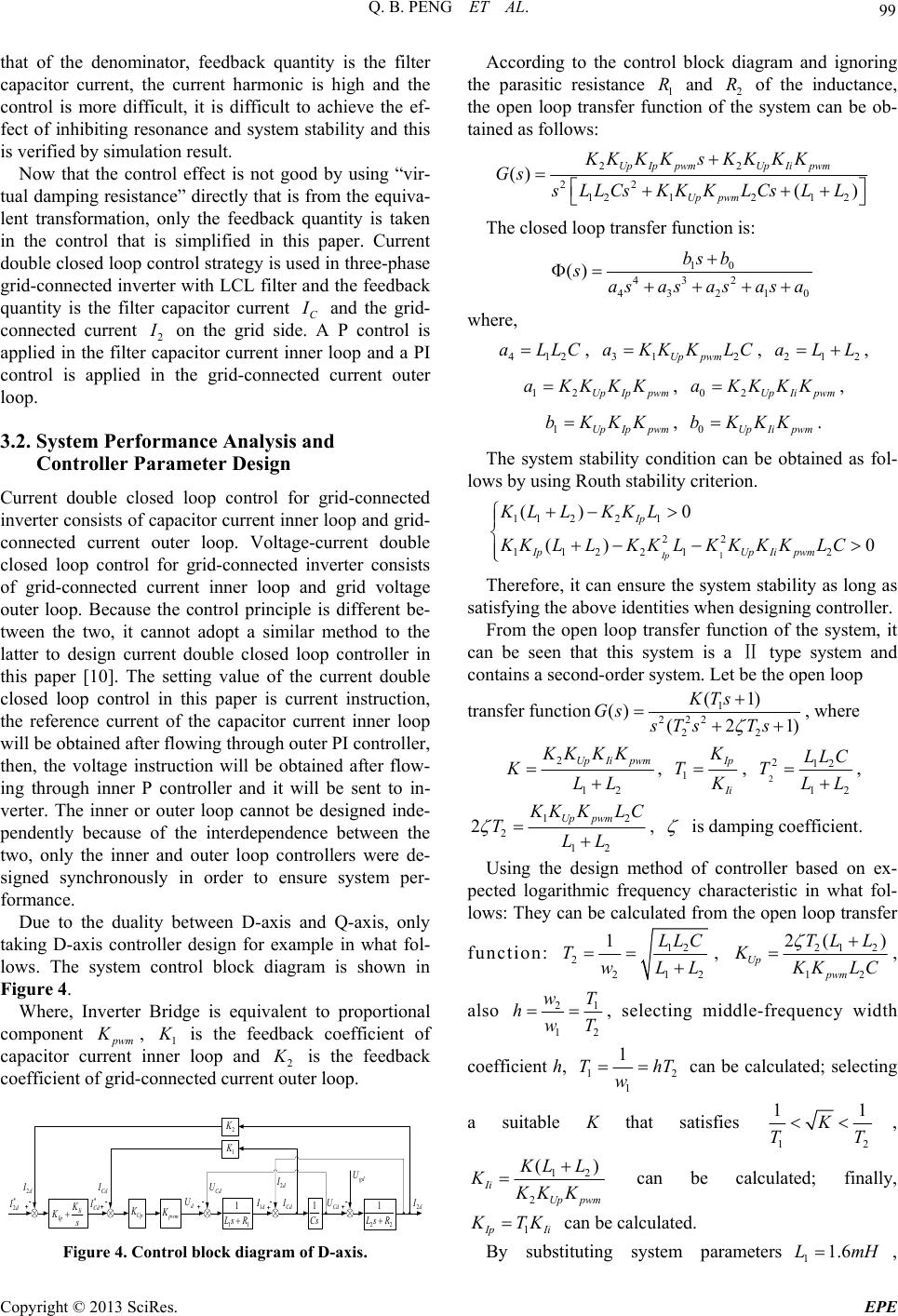 Q. B. PENG ET AL. 99 that of the denominator, feedback quantity is the filter capacitor current, the current harmonic is high and the control is more difficult, it is difficult to achieve the ef- fect of inhibiting resonance and system stability and this is verified by simulation result. Now that the control effect is not good by using “vir- tual damping resistance” directly that is from the equiva- lent transformation, only the feedback quantity is taken in the control that is simplified in this paper. Current double closed loop control strategy is used in three-phase grid-connected inverter with LCL filter and the feedback quantity is the filter capacitor current C I and the grid- connected current 2 I on the grid side. A P control is applied in the filter capacitor current inner loop and a PI control is applied in the grid-connected current outer loop. 3.2. System Performance Analysis and Controller Parameter Design Current double closed loop control for grid-connected inverter consists of capacitor current inner loop and grid- connected current outer loop. Voltage-current double closed loop control for grid-connected inverter consists of grid-connected current inner loop and grid voltage outer loop. Because the control principle is different be- tween the two, it cannot adopt a similar method to the latter to design current double closed loop controller in this paper [10]. The setting value of the current double closed loop control in this paper is current instruction, the reference current of the capacitor current inner loop will be obtained after flowing through outer PI controller, then, the voltage instruction will be obtained after flow- ing through inner P controller and it will be sent to in- verter. The inner or outer loop cannot be designed inde- pendently because of the interdependence between the two, only the inner and outer loop controllers were de- signed synchronously in order to ensure system per- formance. Due to the duality between D-axis and Q-axis, only taking D-axis controller design for example in what fol- lows. The system control block diagram is shown in Figure 4. Where, Inverter Bridge is equivalent to proportional component p wm , 1 K K is the feedback coefficient of capacitor current inner loop and 2 K is the feedback coefficient of grid-connected current outer loop. 11 1 L sR 1 Cs 22 1 L sR 1d I 2d I Cd I Cd U d U g d U Cd U 2d I Ii Ip K K s p wm K Up K 1 K 2 K * 2d I 2d I * Cd I Cd I Figure 4. Control block diagram of D-axis. According to the control block diagram and ignoring the parasitic resistance 1 and 2 of the inductance, the open loop transfer function of the system can be ob- tained as follows: R R 22 22 12121 2 () () Up IppwmUp Iipwm Up pwm KK KKsKK KK Gs sLLCsKKKLCs LL The closed loop transfer function is: 10 432 4321 () bs b sas asas asa 0 where, 412 aLLC , 31 2Up pwm aKKKLC , , 21 aLL 2 12 Up Ippwm aKKKK , , 02UpIipwm aKKKK 1Up Ippwm bKKK , . 0UpIi pwm bKKK The system stability condition can be obtained as fol- lows by using Routh stability criterion. 1 11 221 22 11221 2 () 0 ()Ip Ip IpUp Iipwm KL LKKL KKLLKKLKKK KLC 0 Therefore, it can ensure the system stability as long as satisfying the above identities when designing controller. From the open loop transfer function of the system, it can be seen that this system is a Ⅱ type system and contains a second-order system. Let be the open loop transfer function1 222 22 (1) () (2 KTs Gs sTs Ts 1) , where 2 12 Up Ii pwm KK KK KLL , 1 I p I i K T K , 2 212 12 LLC TLL , 1 2 12 2Uppwm 2 K KK LC TLL , is damping coefficient. Using the design method of controller based on ex- pected logarithmic frequency characteristic in what fol- lows: They can be calculated from the open loop transfer function: 12 2 21 1LLC TwLL 2 , 212 12 2( ) Up pwm TL L K K KLC , also 21 12 wT hwT , selecting middle-frequency width coefficient h, 1 1 1 T w 2 h T can be calculated; selecting a suitable K that satisfies 12 11 K TT , 12 2 ( Ii Up pwm ) K LL KKK K can be calculated; finally, 1 I pIi K TK can be calculated. By substituting system parameters11.6LmH , Copyright © 2013 SciRes. EPE 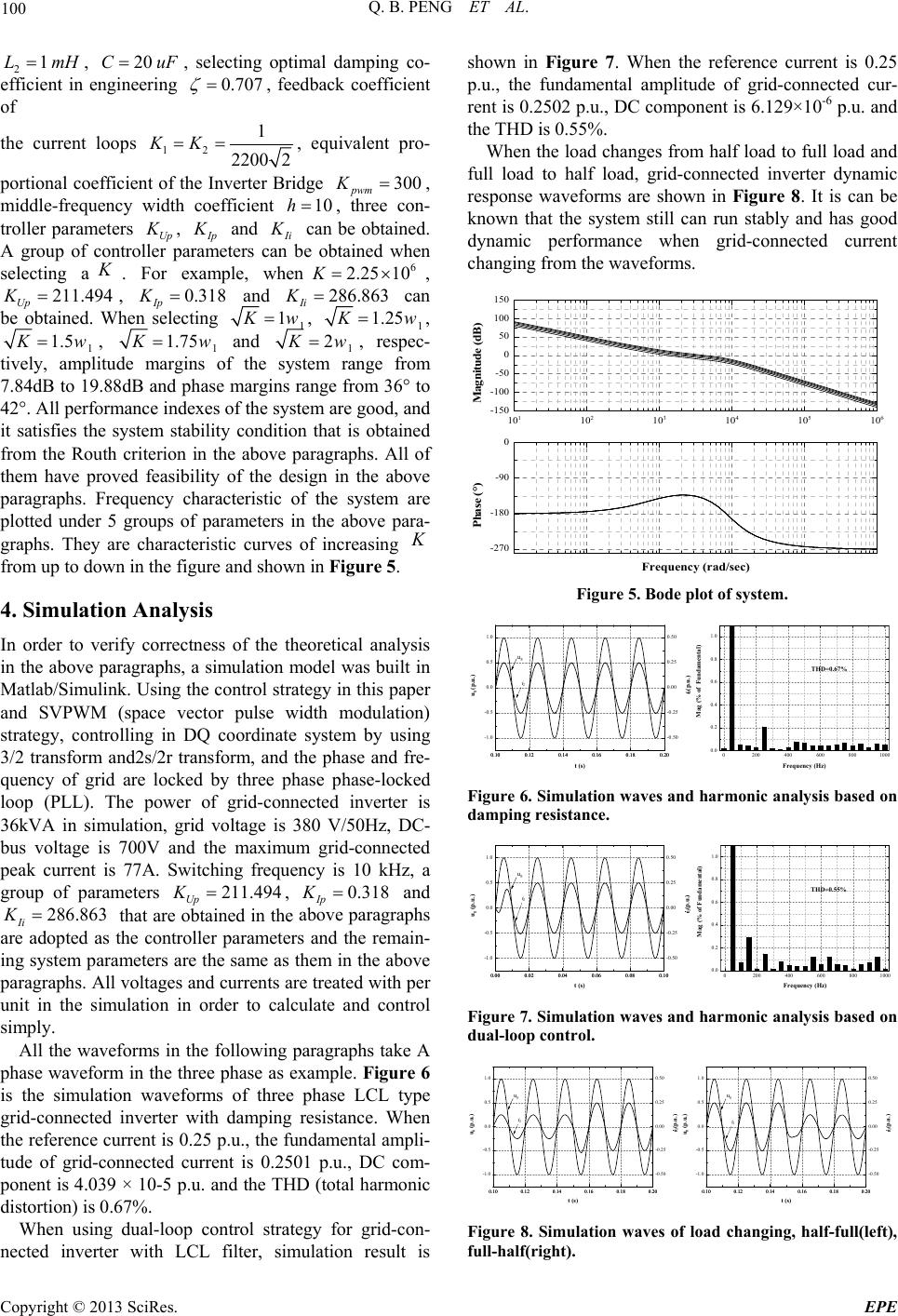 Q. B. PENG ET AL. 100 2, , selecting optimal damping co- efficient in engineering 1LmH20CuF 0.707 , feedback coefficient of the current loops 12 1 2200 2 KK , equivalent pro- portional coefficient of the Inverter Bridge 300 pwm K , middle-frequency width coefficient , three con- troller parameters Up 10h K , I p K and I i K can be obtained. A group of controller parameters can be obtained when selecting a K . For example, when, Up , Ip and can be obtained. When selecting 6 2.25 10 286.863 K Ii K21K1.494 0.318K 1 1 K w, 1 1.25 K w, 1 1.5 K w, 1 1.75 K w and 1 2 K w, respec- tively, amplitude margins of the system range from 7.84dB to 19.88dB and phase margins range from 36° to 42°. All performance indexes of the system are good, and it satisfies the system stability condition that is obtained from the Routh criterion in the above paragraphs. All of them have proved feasibility of the design in the above paragraphs. Frequency characteristic of the system are plotted under 5 groups of parameters in the above para- graphs. They are characteristic curves of increasing K from up to down in the figure and shown in Figure 5. 4. Simulation Analysis In order to verify correctness of the theoretical analysis in the above paragraphs, a simulation model was built in Matlab/Simulink. Using the control strategy in this paper and SVPWM (space vector pulse width modulation) strategy, controlling in DQ coordinate system by using 3/2 transform and2s/2r transform, and the phase and fre- quency of grid are locked by three phase phase-locked loop (PLL). The power of grid-connected inverter is 36kVA in simulation, grid voltage is 380 V/50Hz, DC- bus voltage is 700V and the maximum grid-connected peak current is 77A. Switching frequency is 10 kHz, a group of parameters , and that are obtained in the above paragraphs are adopted as the controller parameters and the remain- ing system parameters are the same as them in the above paragraphs. All voltages and currents are treated with per unit in the simulation in order to calculate and control simply. 211.494 Up K0.318 Ip K 286.863 Ii K All the waveforms in the following paragraphs take A phase waveform in the three phase as example. Figure 6 is the simulation waveforms of three phase LCL type grid-connected inverter with damping resistance. When the reference current is 0.25 p.u., the fundamental ampli- tude of grid-connected current is 0.2501 p.u., DC com- ponent is 4.039 × 10⁻⁵ p.u. and the THD (total harmonic distortion) is 0.67%. When using dual-loop control strategy for grid-con- nected inverter with LCL filter, simulation result is shown in Figure 7. When the reference current is 0.25 p.u., the fundamental amplitude of grid-connected cur- rent is 0.2502 p.u., DC component is 6.129×10⁻⁶ p.u. and the THD is 0.55%. When the load changes from half load to full load and full load to half load, grid-connected inverter dynamic response waveforms are shown in Figure 8. It is can be known that the system still can run stably and has good dynamic performance when grid-connected current changing from the waveforms. -270 -180 -90 0 Phase (°) Frequency (rad/sec) 10 1 10 2 10 3 10 4 10 5 10 6 -150 -100 -50 0 50 100 150 Magnitude (dB) Figure 5. Bode plot of system. 0200400 600 8001000 0.0 0.2 0.4 0.6 0.8 1.0 Mag (% of Fundamental) Frequency (Hz) THD=0.67% 0.10 0.12 0.140.16 0.18 0.20 -1.0 -0.5 0.0 0.5 1.0 0.10 0.12 0.140.16 0.18 0.20 -0.50 -0.25 0.00 0.25 0.50 t (s) u g (p.u.) u g i 2 i 2 (p.u.) Figure 6. Simulation waves and harmonic analysis based on damping resistance. 0200400 6008001000 0.0 0.2 0.4 0.6 0.8 1.0 Mag (% of Fundamental) Frequency (Hz) THD=0.55% 0.00 0.02 0.04 0.06 0.08 0.10 -1.0 -0.5 0.0 0.5 1.0 0.00 0.02 0.04 0.06 0.08 0.10 -0.50 -0.25 0.00 0.25 0.50 t (s) u g (p.u.) i 2 (p.u.) u g i 2 Figure 7. Simulation waves and harmonic analysis based on dual-loop control. 0.10 0.12 0.14 0.16 0.18 0.20 -1.0 -0.5 0.0 0.5 1.0 0.10 0.12 0.14 0.16 0.18 0.20 -0.50 -0.25 0.00 0.25 0.50 t (s) u g (p.u.) u g i 2 i 2 (p.u.) 0.10 0.12 0.14 0.16 0.18 0.20 -1.0 -0.5 0.0 0.5 1.0 0.10 0.12 0.14 0.16 0.18 0.20 -0.50 -0.25 0.00 0.25 0.50 t (s) u g (p.u.) u g i 2 i 2 (p.u.) Figure 8. Simulation waves of load changing, half-full(left), full-half(right). Copyright © 2013 SciRes. EPE  Q. B. PENG ET AL. Copyright © 2013 SciRes. EPE 101 5. Experimental Results power supply quality of the output: low harmonics, espe- cially has a stronger ability of high harmonic suppression, and has solved the system unstable problem caused by resonance; b) system sufficiency was improved further: the real damping resistance has been canceled, it has no extra loss caused by real damping resistance. An experimental prototype for 3 kVA output power has been successfully implemented based on the theoretical analysis and simulation experiments in the above para- graphs by using TM320F2812 DSP as the digital con- troller. Figure 9 is the experimental waveforms of three phase LCL type grid-connected inverter with damping resistance. In this case, grid-connected current is 4.54 A and THD is 3.54%. When using dual-loop control strat- egy for grid-connected inverter with LCL filter, experi- mental result is shown in Figure 10. By this method, grid-connected current is 4.52 A and THD is 3.68%. It can be obtained from the experimental results. When using the new control strategy, it can achieve the same inhibiting resonance as the method of using real damping resistance. At the same time, good power supply quality of the output can be ensured. 7. Acknowledgements This work is supported by the Key Laboratory of Intelli- gent Computing & Information Processing (Xiangtan University), Ministry of Education and the construct program of the key discipline in hunan province. REFERENCES [1] Y. Q. Wang, F. J. Wu, L. Sun, et al., “Optimized Design of LCL Filter for Minimal Damping Power Loss,” Pro- ceedings of the CSEE, Vol. 30, No. 27, 2010, pp. 90-95. [2] M. Liserre, A. Dell'Aquila and F. Blaabjerg, “Stability Improvements of an LCL-filter Based Three-phase Active Rectifier,” IEEE Annual Power Electronics Specialists Conference, Cairns, 2002. 6. Conclusions The dual-loop control strategy for grid-connected in- verter with LCL filter in this paper can be used to control the currents of three phase grid-connected inverter, and it will let grid-connected inverter has a stronger ability of harmonic suppression. A detailed description about theoretical basis of the control strategy and design me- thod of the controller were given in this paper, the effec- tiveness of the new control strategy has been verified by simulation and prototype experiment. [3] X. H. Wang, X. B. Ruan and S. W. Liu, “Control Strategy for Grid-connected Inverter to Suppress Current Distor- tion Effected by Background Harmonics in Grid Volt- age,” Proceedings of the CSEE, Vol. 31, No. 6, 2011, pp. 7-14. [4] C. H. Zhang, Y. Ye, A. Chen, et al., “Research on Grid-connected Photovoltaic Inverter Based on Output Current Control,” Transactions of China Electrotechnical Society, Vol. 22, No. 8, 2007, pp. 41-45. Compare with the control method of inhibiting reso- nance by using damping resistance, the new control me- thod in this paper has characters as follows: a) good [5] T . C. Y. Wang,Z. H .Ye,G. Sinha,et al., “Output Filter Design for a Grid-interconnected Three-phase In- verter,” IEEE PESC’03, Acapulco, Mexico, 2003. t (15ms/grid) U g (200V/grid) i 2 (5A/grid) U g i 2 [6] Z. Y. Xu, A. G. Xu and S. J. Xie, “Dual-loop Grid Cur- rent Control Technique for Grid-connected Inverter Using an LCL Filter,” Proceedings of the CSEE, Vol. 29, No. 27, 2009, pp. 36-41. [7] M. Malinowski and S. Bernet, “A Simple Voltage Sen- sorless Active Damping Scheme for Three-phase PWM Converters with an LCL Filter,” IEEE Transactions on Industry Electronics, Vol. 55, No. 4, 2008, pp. 1876-1880. Figure 9. Experimental waves based on damping resistance. [8] Ji Bao-jian, F. Hong and J. F. Zhao, “A Non-isolated Three-level Dual Buck Photovoltaic Grid-connected In- verter,” Proceedings of the CSEE, Vol. 32, No. 12, 2007, pp. 7-13. t (15ms/grid) U g (200V/grid) i 2 (5A/grid) U g i 2 [9] B. C. Wang, X. Q. Guo, Q. Mei, et al., “DC Injection Control for Transformerless PV Grid- connected Invert- ers,” Proceedings of the CSEE, Vol. 29, No. 36, 2009, pp. 23-28. [10] F. Liu, S. X. Duan and X. M. Zha, “Design of Two Loop Controller in Grid-connected Inverter with LCL Filter,” Proceedings of the CSEE, Vol. 29, No. S1, 2009, pp. 234-240. Figure 10. Experimental w ave s based on dual-loop co ntr ol. |