P. BEIRÃO, C. MALÇA 73
but as the depth increases, the radius of the circular mo-
tion decreases. The whole system containing the hydrau-
lic PTO is assumed to be at that depth, not being affected
by the wave motion.
The paper describes several stages concerning the de-
sign, development and construction of a robust, simple
and affordable hydraulic PTO prototype using hydraulic
commercial components for a floating point absorber
WEC. It includes a section describing the initial virtual
simulation and the subsequ ent construction and testing of
didactic hydraulic PTO using hydraulic didactic compo-
nents. The following section describes the development
and building of the prototype using hydraulic commercial
components. Results are presented in an independent
section.
2. Characterisation of the Hydraulic PTO
The partially submerged WEC considered belongs to the
point absorber category [2], since its characteristic di-
mension has a negligible size when compared to the wa-
velength. The two main components are a floating buoy
which is connected to a hydraulic cylinder. The working
principle is quite simple – the buoy is submitted to the
sea waves. As a result the buoy moves upwards under the
influence of a wave crest and moves downwards under
the effect of a wave trough. There will be a reaction force
applied by the hydraulic cylinder to the buoy. The rela-
tive heave motion between the two main components is
converted into electrical energy by means of a hydraulic
PTO [3]. Although six modes of motion are possible [2],
the WEC is assumed to oscillate only in heave.
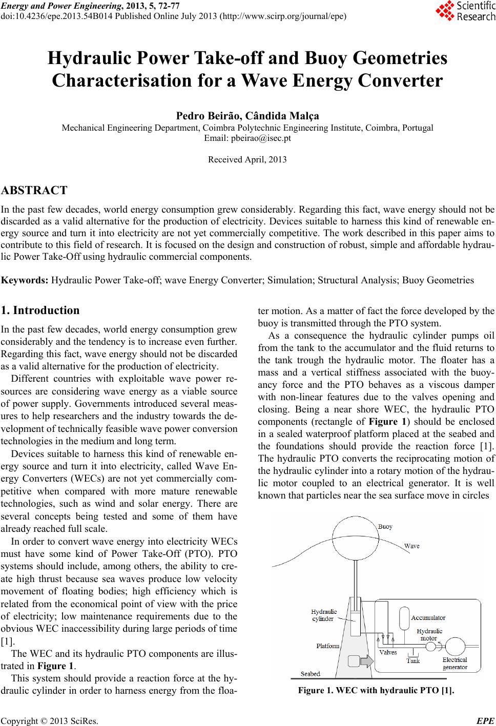
The PTO design is based in a hydraulic circuit, sche-
matised in Figure 2, since this kind of system has several
favourable characteristics. Many WECs have incorpo-
rated hydraulic PTOs in their design [4] as this is an af-
fordable, robust, well proven technology [5].
The hydraulic design also produces a smooth output
power and is dimensionally compact [2]. Additionally,
oil protects the sensitive sliding surfaces from corrosion
and lubricates the seals.
Figure 2. Hydraulic PTO (based on [5]).
Nevertheless there are some disadvantages, since this
kind of system includes oil which is a potential sea pol-
lutant. Also the finite life of seals due to friction and fa-
tigue loading of main components should be taken into
account [2].
For a detailed description of a hydraulic PTO see [1]
and [3].
The main hydraulic components are a double effect
hydraulic cylinder, non-returnable valves, an oil tank, an
accumulator and a hydraulic motor. The hydraulic cylin-
der will be responsible by the relative motion between
the buoy and the mooring platform, but only when the
force applied to the buoy surpasses the hydraulic force
corresponding to the pressure difference between the
accumulator and the tank.
The maximum allowed velocity for hydraulic cylin-
ders is 0.5 m/s, however a velocity of 0.1 m/s should be
used to extend the life of the hydraulic cylinder seals [1].
The successive wave crests and troughs cause a heave
motion to the buoy. As a consequence there is an alter-
nating oil flow which is rectified by the non-returnable
valves. The flow is smoothed by the accumulator [3]
which could also be used as energy storage [1].
Since sea waves are irregular significant variations that
can occur. Therefore the accumulator should have
enough capacity to accommodate the fluid flow for two
or three wave cycles [1]. The goal is to deliver a reason-
able smooth electrical outpu t. The continuous f low of the
oil through the hydr aulic motor is converted in rotational
motion [5] and will drive an electric g enerator, turning at
typically 1000 or 1500 rpm [2], which will be responsi-
ble to convert the wave energy into electricity [3].
There are several options to maintain a continuous ro-
tation of the electrical generator [1]. One is to use a fixed
displacement hydraulic motor to drive a variable speed
electrical generator. Another possibility is using a hy-
draulic motor with variable displacement [3] which al-
lows a flow rate adjustment according to the average
power del ivered by sea w aves.
3. Hydraulic PTO
3.1. Didactic Hydraulic PTO
A virtual simulation of the hydraulic circuit (excluding
the electric generator) of the hydraulic PTO prototype
was made resorting to a specific software.
Figure 3 schematizes the full assembly of the circuit,
which is divided in three parts: the hydraulic circuit of
the hydraulic PTO prototype based on Figure 2; the hy-
draulic part of the electrohydraulic test circuit and the
electric part of the electrohydraulic test circuit.
Being a passive system without auxiliary power sup-
plies, the aim of the electrohydraulic test circuit was to
impose external forces with different signs and magni-
Copyright © 2013 SciRes. EPE