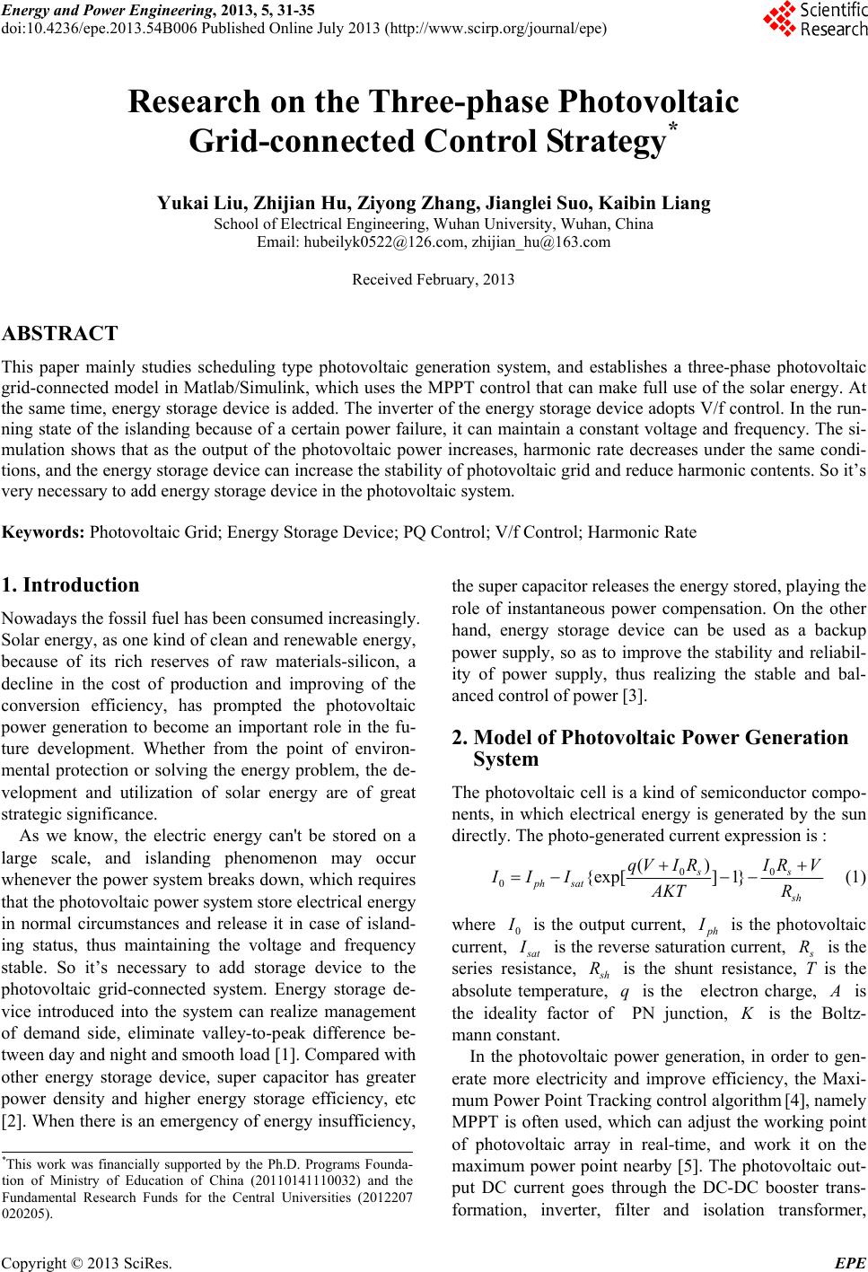
 Energy and Power Engineering, 2013, 5, 31-35 doi:10.4236/epe.2013.54B006 Published Online July 2013 (http://www.scirp.org/journal/epe) Research on the Three-phase Photovoltaic Grid-connected Control Strategy* Yukai Liu, Zhijian Hu, Ziyong Zhang, Jianglei Suo, Kaibin Liang School of Electrical Engineering, Wuhan University, Wuhan, China Email: hubeilyk0522@126.com, zhijian_hu@163.com Received February, 2013 ABSTRACT This paper mainly studies scheduling type photovoltaic generation system, and establishes a three-phase photovoltaic grid-connected model in Matlab/Simulink, which uses the MPPT control that can make full use of the solar energy. At the same time, energy storage device is added. The inverter of the energy storage device adopts V/f control. In the run- ning state of the islanding because of a certain power failure, it can maintain a constant voltage and frequency. The si- mulation shows that as the output of the photovoltaic power increases, harmonic rate decreases under the same condi- tions, and the en ergy stor age device can increase the stab ility of pho tovoltaic gr id and reduce harmonic co ntents. So it’s very necessary to add energy st orage device in the phot ov oltaic system. Keywords: Photovoltaic Grid; Energy Storage Device; PQ Control; V/f Control; Harmonic Rate 1. Introduction Nowadays the fossil fuel has been consumed increasingly. Solar energy, as one kind of clean and renewable energy, because of its rich reserves of raw materials-silicon, a decline in the cost of production and improving of the conversion efficiency, has prompted the photovoltaic power generation to become an important role in the fu- ture development. Whether from the point of environ- mental protection or solving the energy problem, the de- velopment and utilization of solar energy are of great strategic significance. As we know, the electric energy can't be stored on a large scale, and islanding phenomenon may occur whenever the power system breaks down, which requires that the photovoltaic power system store electrical energy in normal circumstances and release it in case of island- ing status, thus maintaining the voltage and frequency stable. So it’s necessary to add storage device to the photovoltaic grid-connected system. Energy storage de- vice introduced into the system can realize management of demand side, eliminate valley-to-peak difference be- tween day and night and smooth load [1]. Compared with other energy storage device, super capacitor has greater power density and higher energy storage efficiency, etc [2]. When there is an emergency of energy insufficiency, the super capacitor releases the energy stored, playing the role of instantaneous power compensation. On the other hand, energy storage device can be used as a backup power supply, so as to improve the stability and reliabil- ity of power supply, thus realizing the stable and bal- anced control of power [3]. 2. Model of Photovoltaic Power Generation System The photovoltaic cell is a kind of semiconductor compo- nents, in which electrical energy is generated by the sun directly. The photo-generated current expression is : 00 0() {exp[] 1} ss ph satsh qVIRIRV II IAKT R (1) where 0 is the output current, h is the photovoltaic current, I at is the reverse saturation curren t, R is the series resistance, h is the shunt resistance, T is the absolute temperature, is the electron charge, Rq is the ideality factor of PN junction, is the Boltz- mann constant. K In the photovoltaic power generation, in order to gen- erate more electricity and improve efficiency, the Maxi- mum Power Point Tracking control algorithm [4], namely MPPT is often used, which can adjust the working point of photovoltaic array in real-time, and work it on the maximum power point nearby [5]. The photovoltaic out- put DC current goes through the DC-DC booster trans- formation, inverter, filter and isolation transformer, *This work was financially supported by the Ph.D. Programs Founda- tion of Ministry of Education of China (20110141110032) and the Fundamental Research Funds for the Central Universities (2012207 020205). Copyright © 2013 SciRes. EPE 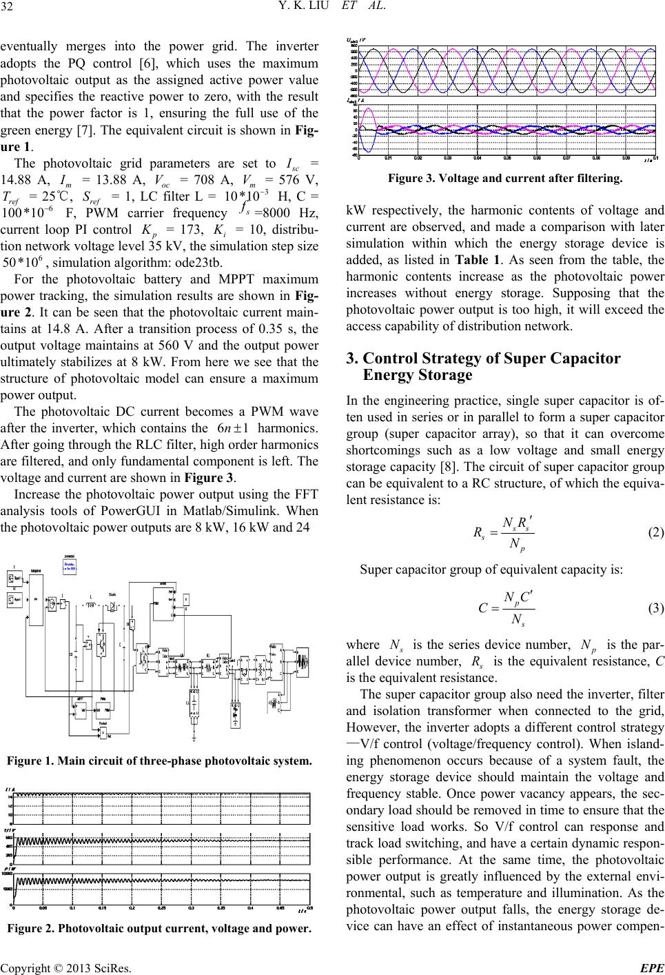 Y. K. LIU ET AL. 32 eventually merges into the power grid. The inverter adopts the PQ control [6], which uses the maximum photovoltaic output as the assigned active power value and specifies the reactive power to zero, with the result that the power factor is 1, ensuring the full use of the green energy [7]. The equivalent circuit is shown in Fig- ure 1. The photovoltaic grid parameters are set to c = 14.88 A, m = 13.88 A, oc = 708 A, = 576 V, = 25℃, ref = 1, LC filter L = H, C = F, PWM carrier frequency Vm V *10 ref T 100 S3 10 6 *10 =8000 Hz, current loop PI control = 173, i = 10, distribu- tion network vo ltage leve l 35 kV, the simula tio n step size , simulation algorithm: ode23tb. 6 *1050For the photovoltaic battery and MPPT maximum power tracking, the simulation results are shown in Fig- ure 2. It can be seen that the photovoltaic current main- tains at 14.8 A. After a transition process of 0.35 s, the output voltage maintains at 560 V and the output power ultimately stabilizes at 8 kW. From here we see that the structure of photovoltaic model can ensure a maximum power output. The photovoltaic DC current becomes a PWM wave after the inverter, which contains the harmonics. After going through the RLC filter, high order harmonics are filtered, and only fundamental component is left. The voltage and current are shown in Figure 3. 6n1 Increase the photovoltaic power output using the FFT analysis tools of PowerGUI in Matlab/Simulink. When the photovoltaic power outputs are 8 kW, 16 kW and 24 Figure 1. Main circuit of three-phase photovoltaic system. Figure 2. Photovoltaic output current, voltage and power. Figure 3. Voltage and current after filtering. kW respectively, the harmonic contents of voltage and current are observed, and made a comparison with later simulation within which the energy storage device is added, as listed in Table 1. As seen from the table, the harmonic contents increase as the photovoltaic power increases without energy storage. Supposing that the photovoltaic power output is too high, it will exceed the access capability of distribution network. 3. Control Strategy of Super Capacitor Energy Storage In the engineering practice, single super capacitor is of- ten used in series or in parallel to form a super capacitor group (super capacitor array), so that it can overcome shortcomings such as a low voltage and small energy storage capacity [8]. The circuit of super capacitor group can be equivalent to a RC structure, of which the equiva- lent resistance is: s sp NR RN (2) Super capacitor group of equivalent capacity is: p NC CN (3) where N is the series device number, N is the par- allel device number, R is the equivalent resistance, C is the equivalent resistance. The super capacitor group also need the inverter, filter and isolation transformer when connected to the grid, However, the inverter adopts a different control strategy —V/f control (voltage/frequency control). When island- ing phenomenon occurs because of a system fault, the energy storage device should maintain the voltage and frequency stable. Once power vacancy appears, the sec- ondary load should be removed in time to ensure that the sensitive load works. So V/f control can response and track load switching, and have a certain dynamic respon- sible performance. At the same time, the photovoltaic power output is greatly influenced by the external envi- ronmental, such as temperature and illumination. As the photovoltaic power output falls, the energy storage de- vice can have an effect of instantaneous power compen- Copyright © 2013 SciRes. EPE 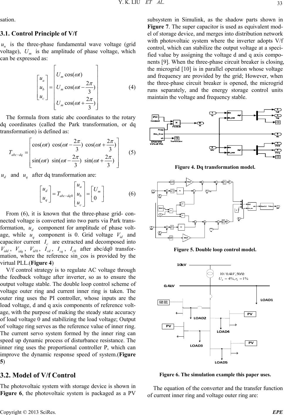 Y. K. LIU ET AL. 33 sation. 3.1. Control Principle of V/f n is the three-phase fundamental wave voltage (grid voltage), m is the amplitude of phase voltage, which can be expressed as: uU cos( ) 2 cos( ) 3 2 cos( ) 3 m a bm c m Ut u uU t uUt (4) The formula from static abc coordinates to the rotary dq coordinates (called the Park transformation, or dq transformation) is defined as: 22 cos() cos() cos() 33 22 sin() sin() sin() 33 abc dq tt t T tt t (5) d u and after dq transformation are: q u 00 a dm abc dqb q c u uU Tu uu (6) From (6), it is known that the three-phase grid- con- nected voltage is converted into two parts via Park trans- formation, component for amplitude of phase volt- age, while q u component is 0. Grid voltage id V and capacitor current d u c are extracted and decomposed into idd , idq , 0id , cd VVV , cq , 0c I after abc/dq0 transfor- mation, where the reference sin_cos is provided by the virtual PL L.(Figu r e 4) V/f control strategy is to regulate AC voltage through the feedback voltage after inverter, so as to ensure the output voltage stable. The double loop control scheme of voltage outer ring and current inner ring is taken. The outer ring uses the PI controller, whose inputs are the load voltage, d and q axis components of reference volt- age, with the purpose of making the steady state accuracy of load voltag e 0 and stabilizing the load voltage; Output of voltage ring serves as the reference value of inner ring. The current servo system formed by the inner ring can speed up dynamic process of disturbance resistance. The inner ring uses the proportional controller P, which can improve the dynamic response speed of system.(Figure 5) 3.2. Model of V/f Control The photovoltaic system with storage device is shown in Figure 6, the photovoltaic system is packaged as a PV subsystem in Simulink, as the shadow parts shown in Figure 7. The super capacitor is used as equivalent mod- el of storage device, and merges into distribution network with photovoltaic system where the inverter adopts V/f control, which can stabilize the output voltage at a speci- fied value by assigning the voltage d and q axis compo- nents [9]. When the three-phase circuit breaker is closing, the microgrid [10] is in parallel operation whose voltage and frequency are provided by the grid; However, when the three-phase circuit breaker is opened, the microgrid runs separately, and the energy storage control units maintain the voltage an d frequency stable. Figure 4. Dq transformation model. Figure 5. Double loop control model. 4%, 1% kk Ur 10 /0.4, 50kV Hz Figure 6. The simulation example this paper uses. The equation of the converter and the transfer function of current inner ring and voltage outer ring are: Copyright © 2013 SciRes. EPE 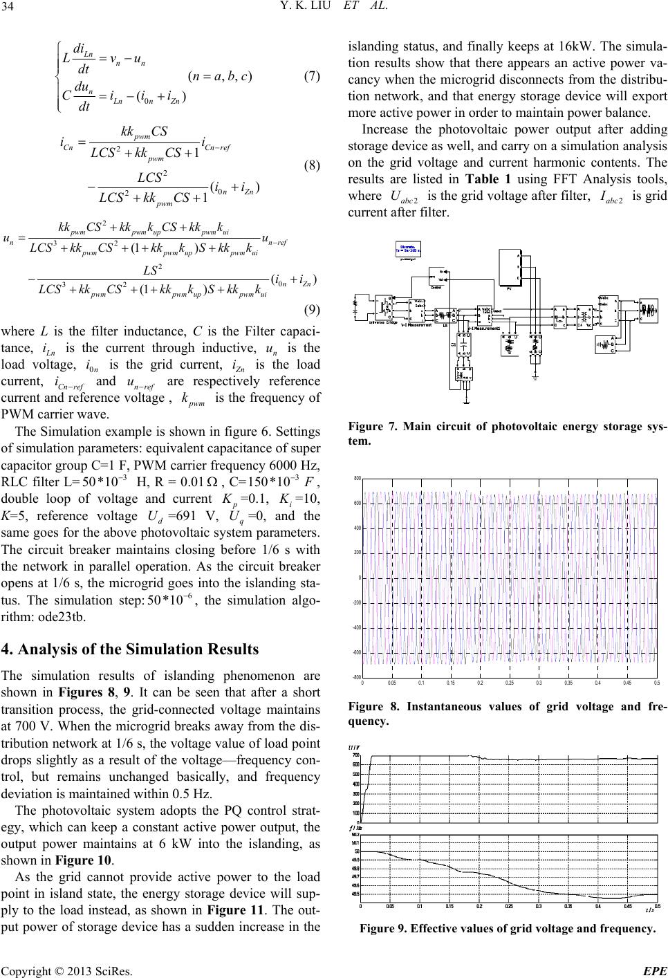 Y. K. LIU ET AL. 34 0 (,, () Ln nn nLnn Zn di Lvu dt n abc du Ciii dt ) (7) 2 2 0 2 1 () 1 pwm CnCn ref pwm nZn pwm kk CS ii LCSkkCS LCS ii LCSkkCS (8) 2 32 2 0 32 (1 ) () (1 ) pwmpwm uppwm ui nnref pwmpwm uppwm ui nZn pwmpwm uppwm ui kkCSkkk CSkkk uu LCSkkCS kkkSkkk LS ii LCSkkCSkkkS kkk (9) where L is the filter inductance, C is the Filter capaci- tance, n is the current through inductive, n is the load voltage, 0n is the grid current, i u i n i is the load current, Cn ref and nref are respectively reference current and reference voltage , iu wm k is the frequency of PWM carrier wave. The Simulation example is shown in figure 6. Settings of simulation parameters: equivalent capacitance of super capacitor group C=1 F, PWM carr ier frequen cy 6000 Hz, RLC filter L= H, R = 0.01, C= 3 50*103 150*10 , double loop of voltage and current =0.1, i =10, K=5, reference voltaged=691 Vq U=0, and the same goes for the above photovoltaic system parameters. The circuit breaker maintains closing before 1/6 s with the network in parallel operation. As the circuit breaker opens at 1/6 s, the microgrid goes into the islanding sta- tus. The simulation step:, the simulation algo- rithm: ode23tb. U 50 , 6 *10 4. Analysis of the Simulation Results The simulation results of islanding phenomenon are shown in Figures 8, 9. It can be seen that after a short transition process, the grid-connected voltage maintains at 700 V. When the microgrid breaks away from the dis- tribution network at 1/6 s, the voltage value of load point drops slightly as a result of the voltage—frequency con- trol, but remains unchanged basically, and frequency deviation is maintained within 0.5 Hz. The photovoltaic system adopts the PQ control strat- egy, which can keep a constant active power output, the output power maintains at 6 kW into the islanding, as shown in Figure 10. As the grid cannot provide active power to the load point in island state, the energy storage device will sup- ply to the load instead, as shown in Figure 11. The out- put power of storage device has a sudden increase in the islanding status, and finally keeps at 16kW. The simula- tion results show that there appears an active power va- cancy when the microgrid disconnects from the distribu- tion network, and that energy storage device will export more active power in order to maintain power balance. Increase the photovoltaic power output after adding storage device as well, and carry on a simulation analysis on the grid voltage and current harmonic contents. The results are listed in Table 1 using FFT Analysis tools, where 2abc is the grid voltage after filter, U2abc is grid current after filter. Figure 7. Main circuit of photovoltaic energy storage sys- tem. 00.05 0.1 0.15 0.2 0.25 0.3 0.35 0.4 0.45 0.5 -800 -600 -400 -200 0 200 400 600 800 Uabc 2 Figure 8. Instantaneous values of grid voltage and fre- quency. Figure 9. Effective values of grid voltage and frequency. Copyright © 2013 SciRes. EPE 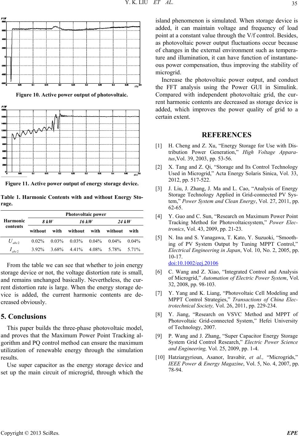 Y. K. LIU ET AL. Copyright © 2013 SciRes. EPE 35 Figure 10. Active power output of photovoltaic. Figure 11. Active power output of energy storage device. Table 1. Harmonic Contents with and without Energy Sto- rage. Photovoltaic power 8 kW 16 kW 24 kW Harmonic contents without with without with withoutwith 2abc U 0.02% 0.03% 0.03% 0.04% 0.04%0.04% 2abc I 3.92% 3.68% 4.41% 4.08% 5.78%5.71% From the table we can see that whether to join energy storage device or not, the voltage distortion rate is small, and remains unchanged basically. Nevertheless, the cur- rent distortion rate is large. When the energy storage de- vice is added, the current harmonic contents are de- creased obviously. 5. Conclusions This paper builds the three-phase photovoltaic model, and proves that the Maximum Power Point Tracking al- gorithm and PQ control method can ensure the maximum utilization of renewable energy through the simulation results. Use super capacitor as the energy storage device and set up the main circuit of microgrid, through which the island phenomenon is simulated. When storage device is added, it can maintain voltage and frequency of load point at a constant value through the V/f control. Besides, as photovoltaic power output fluctuations occur because of changes in the external environment such as tempera- ture and illumination, it can have function of instantane- ous power compensation, thus improving the stability of microgrid. Increase the photovoltaic power output, and conduct the FFT analysis using the Power GUI in Simulink. Compared with independent photovoltaic grid, the cur- rent harmonic contents are decreased as storage device is added, which improves the power quality of grid to a certain extent. REFERENCES [1] H. Cheng and Z. Xu, “Energy Storage for Use with Dis- tribution Power Generation,” High Voltage Appara- tus,Vol. 39, 2003, pp. 53-56. [2] X. Tang and Z. Qi, “Storage and Its Control Technology Used in Microgrid,” Acta Energy Solaris Sinica, Vol. 33, 2012, pp. 517-522. [3] J. Liu, J. Zhang, J. Ma and L. Cao, “Analysis of Energy Storage Technology Applied in Grid-connected PV Sys- tem,” Power System and Clean Energy, Vol. 27, 2011, pp. 62-65. [4] Y. Guo and C. Sun, “Re search on Max imum Power Po int Tracking Method for Photovoltaicsystem,” Power Elec- tronics, Vol. 43, 2009, pp. 21-23. [5] N. Ina and S. Yanagawa, T. Kato, Y. Suzuoki, “Smooth- ing of PV System Output by Tuning MPPT Control,” Electrical Engineering in Japan, Vol. 10, No. 2, 2005, pp. 10-17. doi:10.1002/eej.20106 [6] C. Wang and Z. Xiao, “Integrated Control and Analysis of Microgrid,” Automation of Electric Power System, Vol. 32, 2008, pp. 98-103. [7] Y. Yang and K. Liang, “Photovoltaic Cell Modeling and MPPT Control Strategies,” Transactions of China Elec- trotechnical Society, Vol. 26, 2011, pp. 229-234. [8] Y. Jiang, “Research on VSVC Method and MPPT of Photovoltaic Grid-connected System,” Hefei University of Technology, 2007. [9] P. Wang and J. Zhang, “Super Capacitor Energy Storage System Grid Control Research,” Electric Power Science and Engineering, Vol. 25, 2009, pp. 1-4. [10] Hatziargyrioun, Asanor, Iravabir, et al., “Microgrids,” IEEE Power & Energy Magazine, Vol. 5, No. 4, 2007, pp. 78-94.
|