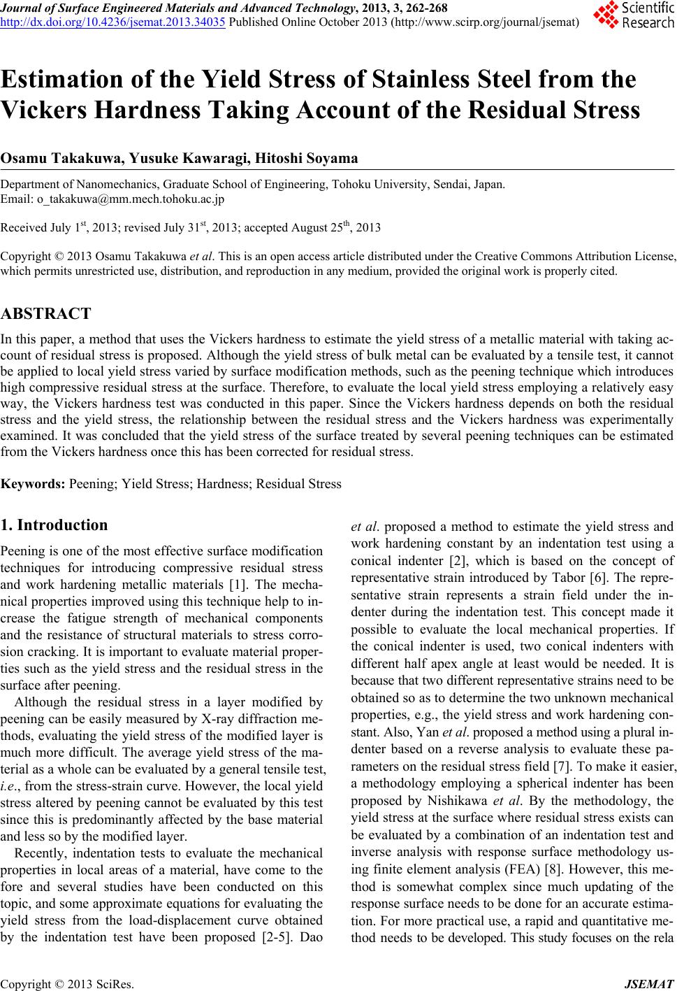
 Journal of Surface Engineered Materials and Advanced Technology, 2013, 3, 262-268 http://dx.doi.org/10.4236/jsemat.2013.34035 Published Online October 2013 (http://www.scirp.org/journal/jsemat) Estimation of the Yield Stress of Stainless Steel from the Vickers Hardness Taking Account of the Residual Stress Osamu Takakuwa, Yusuke Kawaragi, Hitoshi Soyama Department of Nanomechanics, Graduate School of Engineering, Tohoku University, Sendai, Japan. Email: o_takakuwa@mm.mech.tohoku.ac.jp Received July 1st, 2013; revised July 31st, 2013; accepted August 25th, 2013 Copyright © 2013 Osamu Takakuwa et al. This is an open access article distributed under the Creative Commons Attribution License, which permits unrestricted use, distribution, and reproduction in any medium, provided the original work is properly cited. ABSTRACT In this paper, a method that uses the Vickers hardness to estimate the yield stress of a metallic material with taking ac- count of residual stress is proposed. Although the yield stress of bulk metal can be evaluated by a tensile test, it cannot be applied to local yield stress varied by surface modification methods, such as the peening technique which introduces high compressive residual stress at the surface. Therefore, to evaluate the local yield stress employing a relatively easy way, the Vickers hardness test was conducted in this paper. Since the Vickers hardness depends on both the residual stress and the yield stress, the relationship between the residual stress and the Vickers hardness was experimentally examined. It was concluded that the yield stress of the surface treated by several peening techniques can be estimated from the Vickers hardness once this has been corrected for residual stress. Keywords: Peening; Yield Stress; Hardness; Residual Stress 1. Introduction Peening is one of the most effective surface modification techniques for introducing compressive residual stress and work hardening metallic materials [1]. The mecha- nical properties improved using this technique help to in- crease the fatigue strength of mechanical components and the resistance of structural materials to stress corro- sion cracking. It is important to evaluate material proper- ties such as the yield stress and the residual stress in the surface after peening. Although the residual stress in a layer modified by peening can be easily measured by X-ray diffraction me- thods, evaluating the yield stress of the modified layer is much more difficult. The average yield stress of the ma- terial as a whole can be evaluated by a general tensile test, i.e., from the stress-strain curve. However, the local yield stress altered by peening cannot be evaluated by this test since this is predominantly affected by the base material and less so by the modified layer. Recently, indentation tests to evaluate the mechanical properties in local areas of a material, have come to the fore and several studies have been conducted on this topic, and some approximate equations for evaluating the yield stress from the load-displacement curve obtained by the indentation test have been proposed [2-5]. Dao et al. proposed a method to estimate the yield stress and work hardening constant by an indentation test using a conical indenter [2], which is based on the concept of representative strain introduced by Tabor [6]. The repre- sentative strain represents a strain field under the in- denter during the indentation test. This concept made it possible to evaluate the local mechanical properties. If the conical indenter is used, two conical indenters with different half apex angle at least would be needed. It is because that two different representative strains need to be obtained so as to determine the two unknown mechanical properties, e.g., the yield stress and work hardening con- stant. Also, Yan et al. proposed a method using a plural in- denter based on a reverse analysis to evaluate these pa- rameters on the residual stress field [7]. To make it easier, a methodology employing a spherical indenter has been proposed by Nishikawa et al. By the methodology, the yield stress at the surface where residual stress exists can be evaluated by a combination of an indentation test and inverse analysis with response surface methodology us- ing finite element analysis (FEA) [8]. However, this me- thod is somewhat complex since much updating of the response surface needs to be done for an accurate estima- tion. For more practical use, a rapid and quantitative me- thod needs to be developed. This study focuses on the rela Copyright © 2013 SciRes. JSEMAT 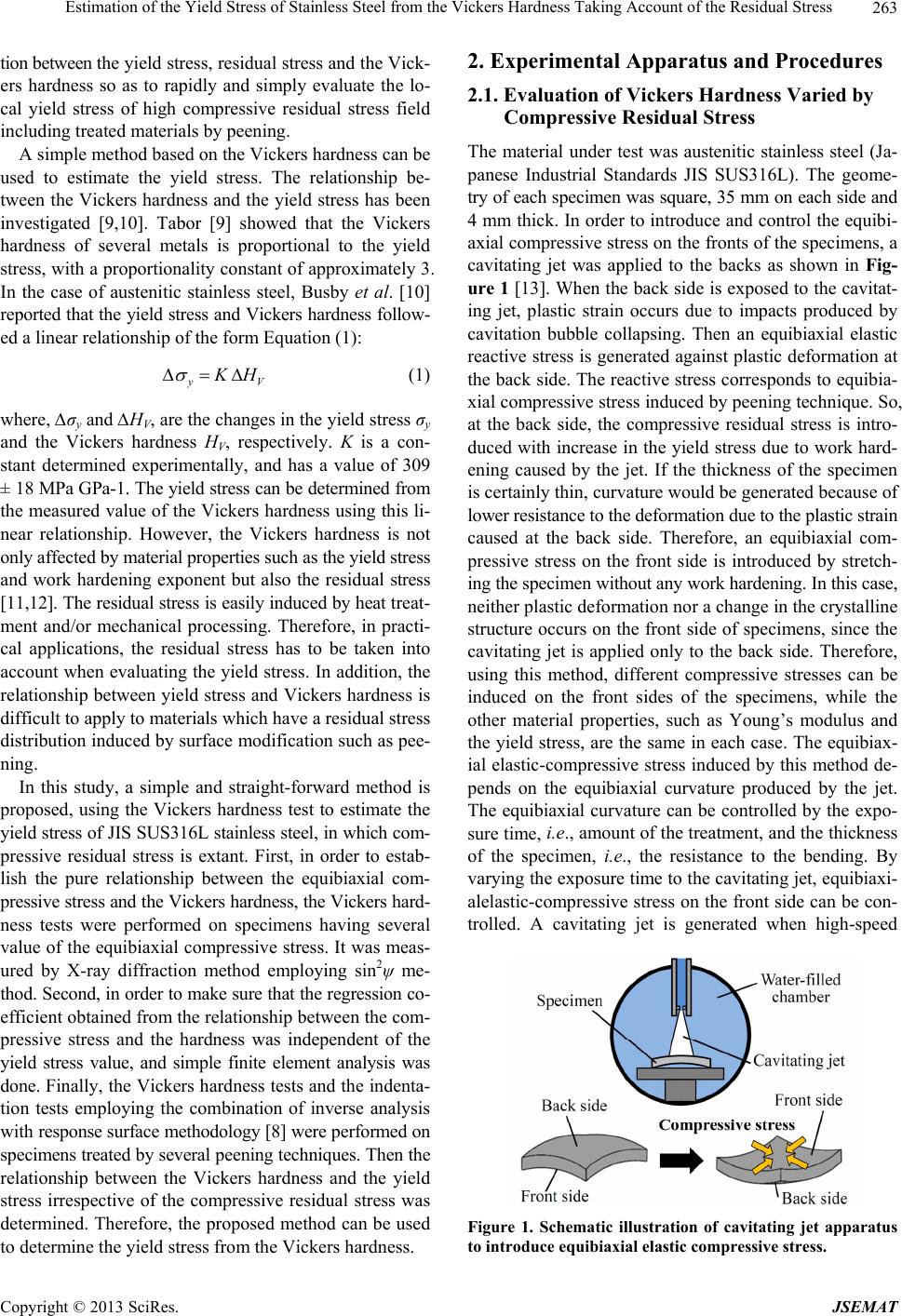 Estimation of the Yield Stress of Stainless Steel from the Vickers Hardness Taking Account of the Residual Stress 263 tion between the yield stress, residual stress and the Vick- ers hardness so as to rapidly and simply evaluate the lo- cal yield stress of high compressive residual stress field including treated materials by peening. A simple method based on the Vickers hardness can be used to estimate the yield stress. The relationship be- tween the Vickers hardness and the yield stress has been investigated [9,10]. Tabor [9] showed that the Vickers hardness of several metals is proportional to the yield stress, with a proportionality constant of approximately 3. In the case of austenitic stainless steel, Busby et al. [10] reported that the yield stress and Vickers hardness follow- ed a linear relationship of the form Equation (1): V H (1) where, ∆σy and ∆HV, are the changes in the yield stress σy and the Vickers hardness HV, respectively. K is a con- stant determined experimentally, and has a value of 309 ± 18 MPa GPa-1. The yield stress can be determined from the measured value of the Vickers hardness using this li- near relationship. However, the Vickers hardness is not only affected by material properties such as the yield stress and work hardening exponent but also the residual stress [11,12]. The residual stress is easily induced by heat treat- ment and/or mechanical processing. Therefore, in practi- cal applications, the residual stress has to be taken into account when evaluating the yield stress. In addition, the relationship between yield stress and Vickers hardness is difficult to apply to materials which have a residual stress distribution induced by surface modification such as pee- ning. In this study, a simple and straight-forward method is proposed, using the Vickers hardness test to estimate the yield stress of JIS SUS316L stainless steel, in which com- pressive residual stress is extant. First, in order to estab- lish the pure relationship between the equibiaxial com- pressive stress and the Vickers hardness, the Vickers hard- ness tests were performed on specimens having several value of the equibiaxial compressive stress. It was meas- ured by X-ray diffraction method employing sin2ψ me- thod. Second, in order to make sure that the regression co- efficient obtained from the relationship between the com- pressive stress and the hardness was independent of the yield stress value, and simple finite element analysis was done. Finally, the Vickers hardness tests and the indenta- tion tests employing the combination of inverse analysis with response surface methodology [8] were performed on specimens treated by several peening techniques. Then the relationship between the Vickers hardness and the yield stress irrespective of the compressive residual stress was determined. Therefore, the proposed method can be used to determine the yield stress from the Vickers hardness. 2. Experimental Apparatus and Procedures 2.1. Evaluation of Vickers Hardness Varied by Compressive Residual Stress The material under test was austenitic stainless steel (Ja- panese Industrial Standards JIS SUS316L). The geome- try of each specimen was square, 35 mm on each side and 4 mm thick. In order to introduce and control the equibi- axial compressive stress on the fronts of the specimens, a cavitating jet was applied to the backs as shown in Fig- ure 1 [13]. When the back side is exposed to the cavitat- ing jet, plastic strain occurs due to impacts produced by cavitation bubble collapsing. Then an equibiaxial elastic reactive stress is generated against plastic deformation at the back side. The reactive stress corresponds to equibia- xial compressive stress induced by peening technique. So, at the back side, the compressive residual stress is intro- duced with increase in the yield stress due to work hard- ening caused by the jet. If the thickness of the specimen is certainly thin, curvature would be generated because of lower resistance to the deformation due to the plastic strain caused at the back side. Therefore, an equibiaxial com- pressive stress on the front side is introduced by stretch- ing the specimen without any work hardening. In this case, neither plastic deformation nor a change in the crystalline structure occurs on the front side of specimens, since the cavitating jet is applied only to the back side. Therefore, using this method, different compressive stresses can be induced on the front sides of the specimens, while the other material properties, such as Young’s modulus and the yield stress, are the same in each case. The equibiax- ial elastic-compressive stress induced by this method de- pends on the equibiaxial curvature produced by the jet. The equibiaxial curvature can be controlled by the expo- sure time, i.e., amount of the treatment, and the thickness of the specimen, i.e., the resistance to the bending. By varying the exposure time to the cavitating jet, equibiaxi- alelastic-compressive stress on the front side can be con- trolled. A cavitating jet is generated when high-speed Figure 1. Schematic illustration of cavitating jet apparatus to introduce equibiaxial elastic compre ssive str ess. Copyright © 2013 SciRes. JSEMAT 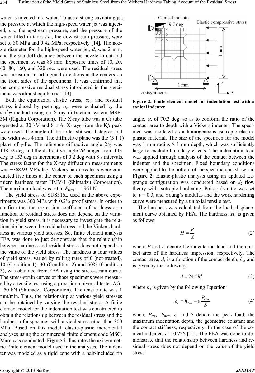 Estimation of the Yield Stress of Stainless Steel from the Vickers Hardness Taking Account of the Residual Stress 264 water is injected into water. To use a strong cavitating jet, the pressure at which the high-speed water jet was inject- ed, i.e., the upstream pressure, and the pressure of the water filled in tank, i.e., the downstream pressure, were set to 30 MPa and 0.42 MPa, respectively [14]. The noz- zle diameter for the high-speed water jet, d, was 2 mm, and the standoff distance between the nozzle throat and the specimen, s, was 85 mm. Exposure times of 10, 20, 40, 80, 160, and 320 sec. were used. The residual stress was measured in orthogonal directions at the centers on the front sides of the specimens. It was confirmed that the compressive residual stress introduced in the speci- mens was almost equibiaxial [13]. Both the equibiaxial elastic stress, ee, and residual stress induced by peening, r, were evaluated by the sin2 method using an X-ray diffraction system MSF- 3M (Rigaku Corporation). The X-ray tube was a Cr tube operated at 30 kV and 8 mA. X-rays from the Kβ peak were used. The angle of the soller slit was 1 degree and the width was 4 mm. The diffractive plane was the (3 1 1) plane of γ-Fe. The reference diffractive angle 2 0 was 148.52 deg and the diffractive angle 2θ ranged from 143 deg to 153 deg in increments of 0.2 deg with 8 s intervals. The stress factor for the X-ray diffraction measurements was −368.93 MPa/deg. Vickers hardness tests were con- ducted five times at the center of each specimen using a micro hardness tester HMV-1 (Shimadzu Corporation). The maximum load was set to Pmax = 1.961 N. The yield stress of SUS316L used in the above expe- riments was 300 MPa with 0.2% proof stress. In order to confirm that the regression coefficient of hardness as a function of residual stress does not depend on the varia- tion in yield stress, it is necessary to investigate the rela- tionship between the residual stress and the Vickers hard- ness at various yield stresses. So, finite element analysis FEA was done to just demonstrate that the relationship between hardness and residual stress does not depend on the value of the yield stress. The hardness at four values of yield stress, varied by rolling rates of 0 (not-treated), 10 (Condition 1), 30 (Condition 2) and 50% (Condition 3), was obtained from FEA using the stress-strain curve. The stress-strain curves of those specimens were measur- ed by a tensile test using a precision universal tester AG- I 50 kN (Shimadzu Corporation). The tensile rate was 1 mm/min. Thus, the relationship at various yield stresses can be obtained by varying the residual stress. A finite element model for the indentation test was constructed to obtain the relationship between the residual stress and the hardness of a specimen with a yield stress other than 300 MPa. Based on this model, elastic-plastic incremental analyses using the commercial finite element code MSC. Marc was conducted. Figure 2 illustrates the axisymmet- ric finite element model used in the analyses. The inden- ter was modeled as a rigid cone with a half-included tip Figure 2. Finite element model for indentation test with a conical indenter. angle, , of 70.3 deg, so as to conform the ratio of the contact area to depth with a Vickers indenter. The speci- men was modeled as a homogeneous isotropic elastic- plastic material. The size of the specimen for the model was 1 mm radius × 1 mm depth, which was sufficiently large to exclude boundary effects. The indentation load was applied through analysis of the contact between the indenter and the specimen. Fixed boundary conditions were applied to the bottom of the specimen, as shown in Figure 2. Elastic-plastic analysis using an updated La- grange configuration was conducted based on J2 flow theory with isotropic hardening. Poisson’s ratio was set to = 0.3, and Young’s modulus and the work hardening curve were measured by a uniaxial tensile test. The hardness was calculated from the load, displace- ment curve obtained by FEA. The hardness, H, is given as follows: P H (2) where P and A denote the indentation load and the con- tact area of the hardness impression, respectively. The contact area, A, is a function of the contact depth, hc, and is given by the following: 2 24.5 c h (3) where hc is given by the following Equation: max maxc P hh S (4) where Pmax, h max, , and S denote the peak load, the maximum indentation depth, the geometric constant and the contact stiffness, respectively. In the case of the co- nical indenter, = 0.726 [15]. The FEA was done to de- monstrate that the relationship between hardness and re- sidual stress does not depend on the value of the yield stress. Copyright © 2013 SciRes. JSEMAT  Estimation of the Yield Stress of Stainless Steel from the Vickers Hardness Taking Account of the Residual Stress 265 2.2. Evaluation of Vickers Hardness and the Yield Stress Varied by Several Surface Treatments In order to investigate the variation in Vickers hardness with respect to the variation in yield stress, Vickers hard- ness tests were conducted on several specimens with va- rious yield stresses. The yield stress of these specimens was varied by peening and polishing, according to the conditions described in Tab le 1. In the cavitation peened specimens, processing time per unit length, tp, was changed to vary amount of the treatment. In the laser peened specimens, laser energy, E, was also changed. The yield stress of not-treated specimen (SR heat treat- ment) and rolling rate of 50% specimen were 0.2% proof stress determined by the stress-strain curve. The yield stresses of polished, cavitation peened (CP) and laser peened (LP) specimens were estimated by inverse analy- sis using indentation by a spherical indenter [8], since the tensile test cannot be used to evaluate the yield stress distributed in the sub-surface. The inverse analysis pro- cedure used to estimate the yield stress is described be- low. This method has already constructed in the past re- port [8]. The response surface relating the material para- meters to the indentation load-displacement curves was obtained using FEA of the indentation. Young’s modulus, E, yield stress, y, and the work hardening exponent, n, were defined as material parameters. The response sur- face enables the indentation curve of a material with arbi- trary parameters to be estimated. Using inverse analysis based on a genetic algorithm, the material parameters were obtained by minimizing the error between the ap- proximate values calculated by the response surface and the experimental values obtained by the indentation tests. Table 1. Treatment conditions for the specimen. Evaluated by a tensile test Evaluated by inverse analysis 1 Not-treated 3 Polished 2 Rolling rate 50% 4 Cavitation peening using Cavitating jet in water [16] tp = 1 s/mm 5 Cavitation peening using Cavitating jet in water [16] tp = 4 s/mm 6 Cavitation peening using Cavitating jet in water [16] tp = 16 s/mm 7 Cavitation peening using Cavitating jet in air [17] tp = 20 s/mm 8 Laser peening conducted by Cincinnati E = 6 J 9 Laser peening conducted by Cincinnati E = 10 J 10 Laser peening conducted by Toshiba Co. Ltd. [18] E = 20 mJ Additionally FEA of the indentation was conducted using the material parameters found. If the accuracy of the re- sponse surface was sufficiently high, the FEA result cor- responded to the experimental indentation result. If not, the FEA result was added to the data set of the response surface to improve its accuracy. This updating process was repeated until the accuracy of the response surface was sufficiently high. The effect of residual stress was eliminated by estimating the response surface from the indentation load-displacement curve of a specimen with no residual stress. The validity of this method was veri- fied through application to specimens whose yield stress was known. It had already been confirmed that the yield stress obtained by inverse analysis corresponded well to the yield stress measured by the tensile test [8]. 3. Results and Discussion 3.1. Relationship between Vickers Hardness and the Compressive Stress Figure 3 shows the Vickers hardness, HV, as a function of the equibiaxial elastic stress, ee, obtained by a Vick- ers hardness test conducted on specimens with various residual stress. The compressive stress is presented as ne- gative. It is confirmed that the maximum the equibiaxial elastic-compressive stress induced on the front sides of the specimens whose back sides had been exposed to the cavitating jet was 250 MPa, which is less than the yield stress of 300 MPa of the not-treated specimen, i.e., with- in the range of elastic stress. The measured Vickers hard- ness increases linearly with increasing compressive stress. The line was approximated by the weighted least squares method. The regression coefficient obtained from Figure 3 is (−8.4 ± 1.4) × 10−4. The effect on Vickers hardness due to the compressive stress was obtained by multiply- ing the compressive stress by this gradient. This result can be applied to estimate the Vickers hardness of a ma- terial under compressive residual stress. According to past studies [11,12], the effect of tensile residual stress on the Vickers hardness is greater than that of compressive re- sidual stress. In the case of compressive residual stress, Figure 3. Relationship between residual stress and Vickers hardness of SUS316L. Copyright © 2013 SciRes. JSEMAT 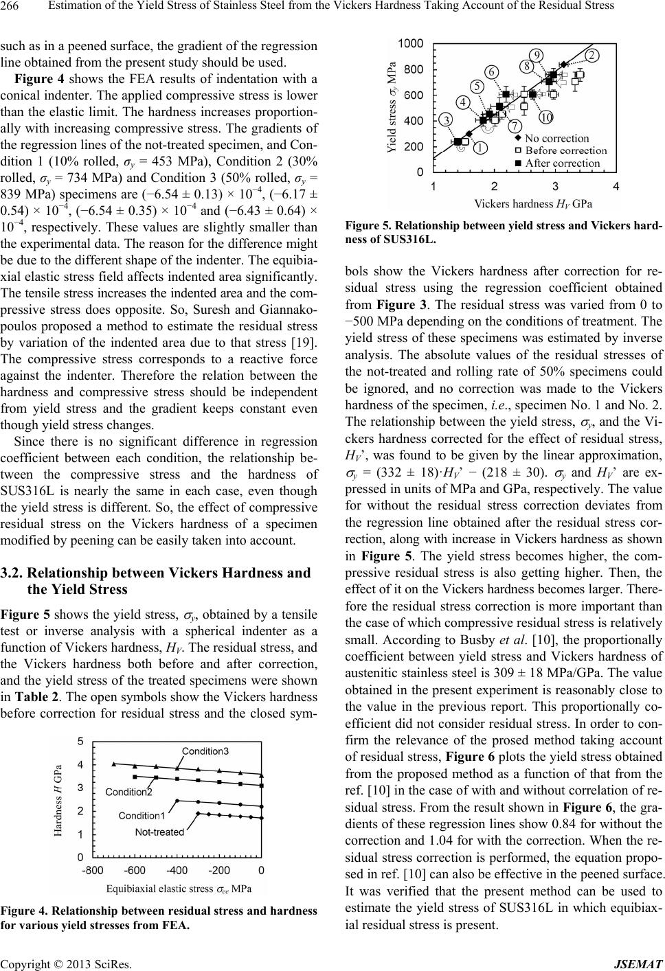 Estimation of the Yield Stress of Stainless Steel from the Vickers Hardness Taking Account of the Residual Stress 266 such as in a peened surface, the gradient of the regression line obtained from the present study should be used. Figure 4 shows the FEA results of indentation with a conical indenter. The applied compressive stress is lower than the elastic limit. The hardness increases proportion- ally with increasing compressive stress. The gradients of the regression lines of the not-treated specimen, and Con- dition 1 (10% rolled, σy = 453 MPa), Condition 2 (30% rolled, σy = 734 MPa) and Condition 3 (50% rolled, σy = 839 MPa) specimens are (−6.54 ± 0.13) × 10−4, (−6.17 ± 0.54) × 10−4, (−6.54 ± 0.35) × 10−4 and (−6.43 ± 0.64) × 10−4, respectively. These values are slightly smaller than the experimental data. The reason for the difference might be due to the different shape of the indenter. The equibia- xial elastic stress field affects indented area significantly. The tensile stress increases the indented area and the com- pressive stress does opposite. So, Suresh and Giannako- poulos proposed a method to estimate the residual stress by variation of the indented area due to that stress [19]. The compressive stress corresponds to a reactive force against the indenter. Therefore the relation between the hardness and compressive stress should be independent from yield stress and the gradient keeps constant even though yield stress changes. Since there is no significant difference in regression coefficient between each condition, the relationship be- tween the compressive stress and the hardness of SUS316L is nearly the same in each case, even though the yield stress is different. So, the effect of compressive residual stress on the Vickers hardness of a specimen modified by peening can be easily taken into account. 3.2. Relationship between Vickers Hardness and the Yield Stress Figure 5 shows the yield stress, y, obtained by a tensile test or inverse analysis with a spherical indenter as a function of Vickers hardness, HV. The residual stress, and the Vickers hardness both before and after correction, and the yield stress of the treated specimens were shown in Table 2. The open symbols show the Vickers hardness before correction for residual stress and the closed sym- Figure 4. Relationship between residual stress and hardness for various yield stresses from FEA. Figure 5. Relationship between yield stress and Vickers hard- ness of SUS316L. bols show the Vickers hardness after correction for re- sidual stress using the regression coefficient obtained from Figure 3. The residual stress was varied from 0 to −500 MPa depending on the conditions of treatment. The yield stress of these specimens was estimated by inverse analysis. The absolute values of the residual stresses of the not-treated and rolling rate of 50% specimens could be ignored, and no correction was made to the Vickers hardness of the specimen, i.e., specimen No. 1 and No. 2. The relationship between the yield stress, y, and the Vi- ckers hardness corrected for the effect of residual stress, HV’, was found to be given by the linear approximation, y = (332 ± 18)·HV’ − (218 ± 30). y and HV’ are ex- pressed in units of MPa and GPa, respectively. The value for without the residual stress correction deviates from the regression line obtained after the residual stress cor- rection, along with increase in Vickers hardness as shown in Figure 5. The yield stress becomes higher, the com- pressive residual stress is also getting higher. Then, the effect of it on the Vickers hardness becomes larger. There- fore the residual stress correction is more important than the case of which compressive residual stress is relatively small. According to Busby et al. [10], the proportionally coefficient between yield stress and Vickers hardness of austenitic stainless steel is 309 ± 18 MPa/GPa. The value obtained in the present experiment is reasonably close to the value in the previous report. This proportionally co- efficient did not consider residual stress. In order to con- firm the relevance of the prosed method taking account of residual stress, Figure 6 plots the yield stress obtained from the proposed method as a function of that from the ref. [10] in the case of with and without correlation of re- sidual stress. From the result shown in Figure 6, the gra- dients of these regression lines show 0.84 for without the correction and 1.04 for with the correction. When the re- sidual stress correction is performed, the equation propo- sed in ref. [10] can also be effective in the peened surface. It was verified that the present method can be used to estimate the yield stress of SUS316L in which equibiax- ial residual stress is present. Copyright © 2013 SciRes. JSEMAT 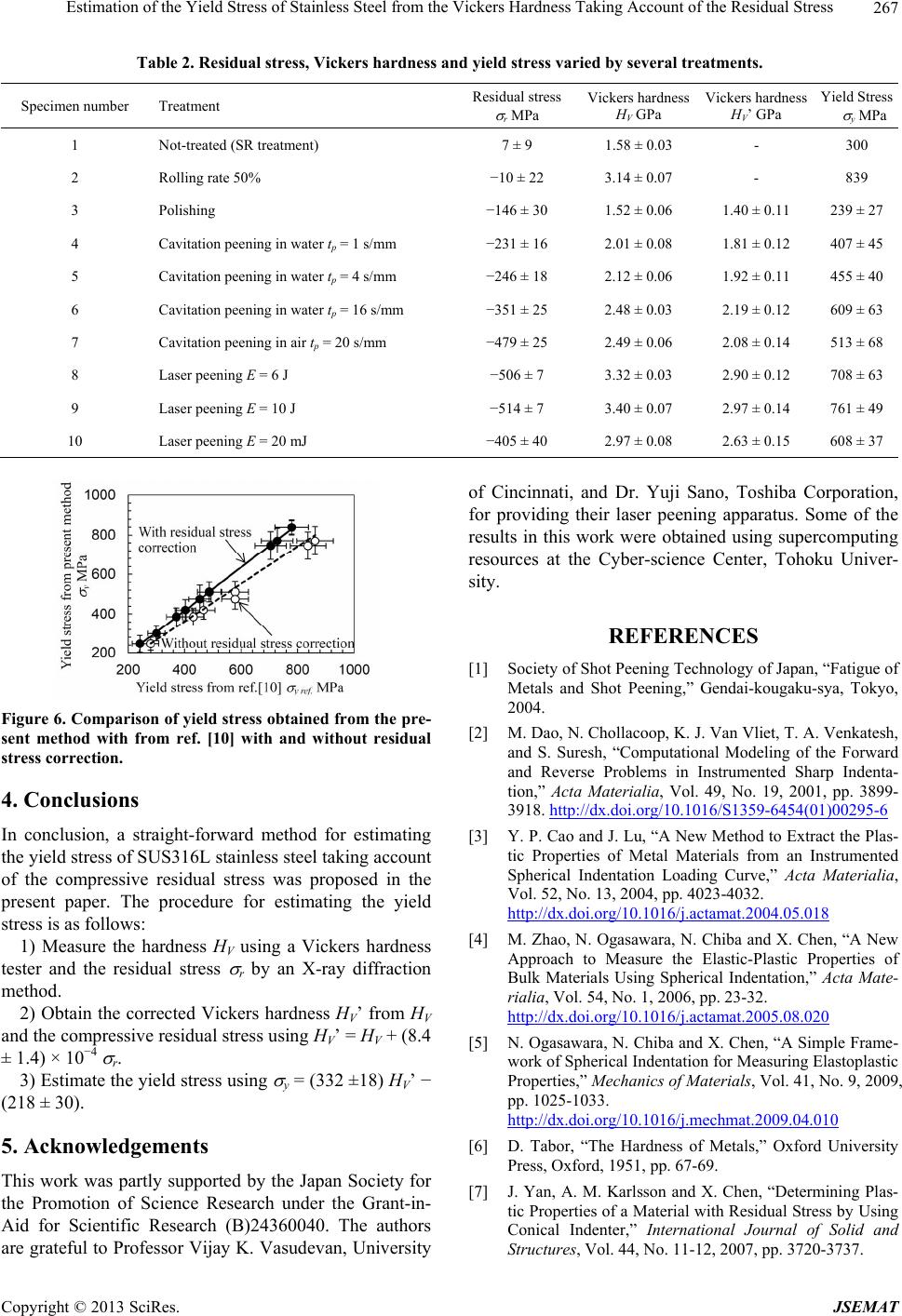 Estimation of the Yield Stress of Stainless Steel from the Vickers Hardness Taking Account of the Residual Stress Copyright © 2013 SciRes. JSEMAT 267 Table 2. Residual stress, Vickers hardness and yield stress var ie d by several treatments. Specimen number Treatment Residual stress r MPa Vickers hardness HV GPa Vickers hardness HV’ GPa Yield Stress y MPa 1 Not-treated (SR treatment) 7 ± 9 1.58 ± 0.03 - 300 2 Rolling rate 50% −10 ± 22 3.14 ± 0.07 - 839 3 Polishing −146 ± 30 1.52 ± 0.06 1.40 ± 0.11 239 ± 27 4 Cavitation peening in water tp = 1 s/mm −231 ± 16 2.01 ± 0.08 1.81 ± 0.12 407 ± 45 5 Cavitation peening in water tp = 4 s/mm −246 ± 18 2.12 ± 0.06 1.92 ± 0.11 455 ± 40 6 Cavitation peening in water tp = 16 s/mm −351 ± 25 2.48 ± 0.03 2.19 ± 0.12 609 ± 63 7 Cavitation peening in air tp = 20 s/mm −479 ± 25 2.49 ± 0.06 2.08 ± 0.14 513 ± 68 8 Laser peening E = 6 J −506 ± 7 3.32 ± 0.03 2.90 ± 0.12 708 ± 63 9 Laser peening E = 10 J −514 ± 7 3.40 ± 0.07 2.97 ± 0.14 761 ± 49 10 Laser peening E = 20 mJ −405 ± 40 2.97 ± 0.08 2.63 ± 0.15 608 ± 37 Figure 6. Comparison of yield stress obtained from the pre- sent method with from ref. [10] with and without residual stress correction. 4. Conclusions In conclusion, a straight-forward method for estimating the yield stress of SUS316L stainless steel taking account of the compressive residual stress was proposed in the present paper. The procedure for estimating the yield stress is as follows: 1) Measure the hardness HV using a Vickers hardness tester and the residual stress r by an X-ray diffraction method. 2) Obtain the corrected Vickers hardness HV’ from HV and the compressive residual stress using HV’ = HV + (8.4 ± 1.4) × 10−4 r. 3) Estimate the yield stress using y = (332 ±18) HV’ − (218 ± 30). 5. Acknowledgements This work was partly supported by the Japan Society for the Promotion of Science Research under the Grant-in- Aid for Scientific Research (B)24360040. The authors are grateful to Professor Vijay K. Vasudevan, University of Cincinnati, and Dr. Yuji Sano, Toshiba Corporation, for providing their laser peening apparatus. Some of the results in this work were obtained using supercomputing resources at the Cyber-science Center, Tohoku Univer- sity. REFERENCES [1] Society of Shot Peening Technology of Japan, “Fatigue of Metals and Shot Peening,” Gendai-kougaku-sya, Tokyo, 2004. [2] M. Dao, N. Chollacoop, K. J. Van Vliet, T. A. Venkatesh, and S. Suresh, “Computational Modeling of the Forward and Reverse Problems in Instrumented Sharp Indenta- tion,” Acta Materialia, Vol. 49, No. 19, 2001, pp. 3899- 3918. http://dx.doi.org/10.1016/S1359-6454(01)00295-6 [3] Y. P. Cao and J. Lu, “A New Method to Extract the Plas- tic Properties of Metal Materials from an Instrumented Spherical Indentation Loading Curve,” Acta Materialia, Vol. 52, No. 13, 2004, pp. 4023-4032. http://dx.doi.org/10.1016/j.actamat.2004.05.018 [4] M. Zhao, N. Ogasawara, N. Chiba and X. Chen, “A New Approach to Measure the Elastic-Plastic Properties of Bulk Materials Using Spherical Indentation,” Acta Mate- rialia, Vol. 54, No. 1, 2006, pp. 23-32. http://dx.doi.org/10.1016/j.actamat.2005.08.020 [5] N. Ogasawara, N. Chiba and X. Chen, “A Simple Frame- work of Spherical Indentation for Measuring Elastoplastic Properties,” Mechanics of Materials, Vol. 41, No. 9, 2009, pp. 1025-1033. http://dx.doi.org/10.1016/j.mechmat.2009.04.010 [6] D. Tabor, “The Hardness of Metals,” Oxford University Press, Oxford, 1951, pp. 67-69. [7] J. Yan, A. M. Karlsson and X. Chen, “Determining Plas- tic Properties of a Material with Residual Stress by Using Conical Indenter,” International Journal of Solid and Structures, Vol. 44, No. 11-12, 2007, pp. 3720-3737. 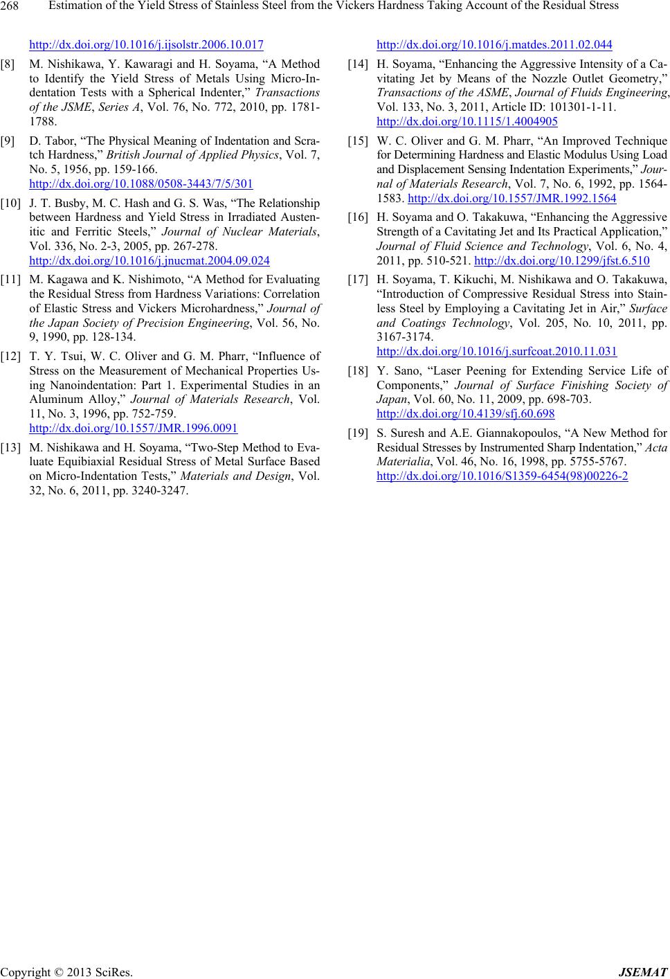 Estimation of the Yield Stress of Stainless Steel from the Vickers Hardness Taking Account of the Residual Stress 268 http://dx.doi.org/10.1016/j.ijsolstr.2006.10.017 [8] M. Nishikawa, Y. Kawaragi and H. Soyama, “A Method to Identify the Yield Stress of Metals Using Micro-In- dentation Tests with a Spherical Indenter,” Transactions of the JSME, Series A, Vol. 76, No. 772, 2010, pp. 1781- 1788. [9] D. Tabor, “The Physical Meaning of Indentation and Scra- tch Hardness,” British Journal of Applied Physics, Vol. 7, No. 5, 1956, pp. 159-166. http://dx.doi.org/10.1088/0508-3443/7/5/301 [10] J. T. Busby, M. C. Hash and G. S. Was, “The Relationship between Hardness and Yield Stress in Irradiated Austen- itic and Ferritic Steels,” Journal of Nuclear Materials, Vol. 336, No. 2-3, 2005, pp. 267-278. http://dx.doi.org/10.1016/j.jnucmat.2004.09.024 [11] M. Kagawa and K. Nishimoto, “A Method for Evaluating the Residual Stress from Hardness Variations: Correlation of Elastic Stress and Vickers Microhardness,” Journal of the Japan Society of Precision Engineering, Vol. 56, No. 9, 1990, pp. 128-134. [12] T. Y. Tsui, W. C. Oliver and G. M. Pharr, “Influence of Stress on the Measurement of Mechanical Properties Us- ing Nanoindentation: Part 1. Experimental Studies in an Aluminum Alloy,” Journal of Materials Research, Vol. 11, No. 3, 1996, pp. 752-759. http://dx.doi.org/10.1557/JMR.1996.0091 [13] M. Nishikawa and H. Soyama, “Two-Step Method to Eva- luate Equibiaxial Residual Stress of Metal Surface Based on Micro-Indentation Tests,” Materials and Design, Vol. 32, No. 6, 2011, pp. 3240-3247. http://dx.doi.org/10.1016/j.matdes.2011.02.044 [14] H. Soyama, “Enhancing the Aggressive Intensity of a Ca- vitating Jet by Means of the Nozzle Outlet Geometry,” Transactions of the ASME, Journal of Fluids Engineering, Vol. 133, No. 3, 2011, Article ID: 101301-1-11. http://dx.doi.org/10.1115/1.4004905 [15] W. C. Oliver and G. M. Pharr, “An Improved Technique for Determining Hardness and Elastic Modulus Using Load and Displacement Sensing Indentation Experiments,” Jour- nal of Materials Research, Vol. 7, No. 6, 1992, pp. 1564- 1583. http://dx.doi.org/10.1557/JMR.1992.1564 [16] H. Soyama and O. Takakuwa, “Enhancing the Aggressive Strength of a Cavitating Jet and Its Practical Application,” Journal of Fluid Science and Technology, Vol. 6, No. 4, 2011, pp. 510-521. http://dx.doi.org/10.1299/jfst.6.510 [17] H. Soyama, T. Kikuchi, M. Nishikawa and O. Takakuwa, “Introduction of Compressive Residual Stress into Stain- less Steel by Employing a Cavitating Jet in Air,” Surface and Coatings Technology, Vol. 205, No. 10, 2011, pp. 3167-3174. http://dx.doi.org/10.1016/j.surfcoat.2010.11.031 [18] Y. Sano, “Laser Peening for Extending Service Life of Components,” Journal of Surface Finishing Society of Japan, Vol. 60, No. 11, 2009, pp. 698-703. http://dx.doi.org/10.4139/sfj.60.698 [19] S. Suresh and A.E. Giannakopoulos, “A New Method for Residual Stresses by Instrumented Sharp Indentation,” Acta Materialia, Vol. 46, No. 16, 1998, pp. 5755-5767. http://dx.doi.org/10.1016/S1359-6454(98)00226-2 Copyright © 2013 SciRes. JSEMAT
|