Paper Menu >>
Journal Menu >>
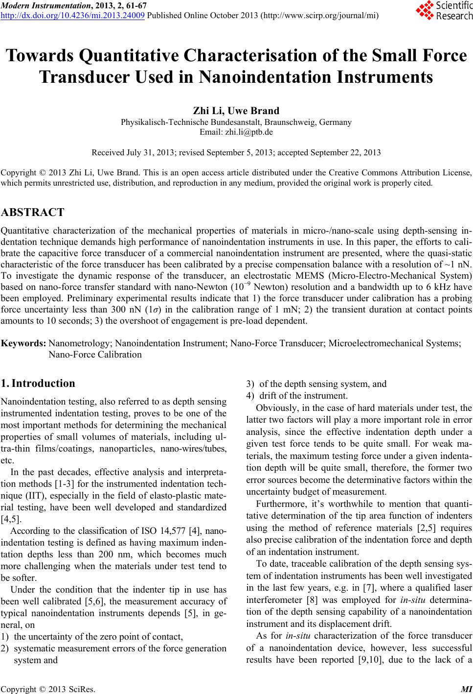 Modern Instrumentation, 2013, 2, 61-67 http://dx.doi.org/10.4236/mi.2013.24009 Published Online October 2013 (http://www.scirp.org/journal/mi) Copyright © 2013 SciRes. MI Towards Quantitative Characterisation of the Small Forc e Transducer Used in Nanoindentation Instruments Zhi Li, Uwe Brand Physikalisch-Technische Bundesanstalt, Braunschweig, Germany Email: zhi.li@ptb.de Received July 31, 2013; revised September 5, 2013; accepted September 22, 2013 Copyright © 2013 Zhi Li, Uwe Brand. This is an open access article distributed under the Creative Commons Attribution License, which permits unrestricted use, distribution, and reproduction in any medium, provided the original work is properly cited. ABSTRACT Quantitative characterization of the mechanical properties of materials in micro-/nano-scale using depth-sensing in- dentation technique demands high performance of nanoindentation instruments in use. In this paper, the efforts to cali- brate the capacitive force transducer of a commercial nanoindentation instrument are presented, where the quasi-static characteristic of the force transducer has been calibrated by a precise compensation balance with a resolution of ~1 nN. To investigate the dynamic response of the transducer, an electrostatic MEMS (Micro-Electro-Mechanical System) based on nano-force transfer standard with nano-Newton (10−9 Newton) resolution and a bandwidth up to 6 kHz have been employed. Preliminary experimental results indicate that 1) the force transducer under calibration has a probing force uncertainty less than 300 nN (1σ) in the calibration range of 1 mN; 2) the transient duration at contact points amounts to 10 seconds; 3) the overshoot of engagement is pre-load dependent. Keywords: Nanometrology; Nanoindentation Instrument; Nano-Force Transducer; Microelectromechanical Systems; Nano-Force Calibration 1. Introduction Nanoindentation testing, also referred to as depth sensing instrumented indentation testing, proves to be one of the most important methods for determining the mechanical properties of small volumes of materials, including ul- tra-thin films/coatings, nanoparticles, nano-wires/tubes, etc. In the past decades, effective analysis and interpreta- tion methods [1-3] for the instrumented indentation tech- nique (IIT), especially in the field of elasto-plastic mate- rial testing, have been well developed and standardized [4,5]. According to the classification of ISO 14,577 [4], nano- indentation testing is defined as having maximum inden- tation depths less than 200 nm, which becomes much more challenging when the materials under test tend to be softer. Under the condition that the indenter tip in use has been well calibrated [5,6], the measurement accuracy of typical nanoindentation instruments depends [5], in ge- neral, on 1) the uncertainty of the zero point of contact, 2) systematic measurement errors of the force generation system and 3) of the depth sensing system, and 4) drift of the instrument. Obviously, in the case of hard materials under test, the latter two factors will play a more important role in error analysis, since the effective indentation depth under a given test force tends to be quite small. For weak ma- terials, the maximum testing force under a given indenta- tion depth will be quite small, therefore, the former two error sources become the determinative factors within the uncertainty budget of measurement. Furthermore, it’s worthwhile to mention that quanti- tative determination of the tip area function of indenters using the method of reference materials [2,5] requires also precise calibration of the indentation force and depth of an indentation instrument. To date, traceable calibration of the depth sensing sys- tem of indentation instruments has been well investigated in the last few years, e.g. in [7], where a qualified laser interferometer [8] was employed for in-situ determina- tion of the depth sensing capability of a nanoindentation instrument and its displacement drift. As for in-situ characterization of the force transducer of a nanoindentation device, however, less successful results have been reported [9,10], due to the lack of a  Z. LI, U. BRAND Copyright © 2013 SciRes. MI 62 qualified nano-force sensing device, which could be ap- plied to in-situ investigate not only the quasi-static but also the dynamic characteristics of nanoindentation in- struments. In this paper, our efforts to in-situ characterize the quasi-static and dynamic performance of a commercial nanoindentation instrument’s force transducer are pre- sented. For the first purpose, a specialized compensation balance has been employed. To undertake the second task, a MEMS-based self-developed nanoforce actuator is utilized. 2. The to Be Calibrated Force Transducer in a Commercial Nanoindentation Instrument The small force transducer investigated in this paper is one of the key components in a commercial nanoindenta- tion instrument (TI 950, Hysitron Inc.). It has been developed on the basis of a typical three- plate capacitive force actuating and sensing configura- tion [11,12] (see also Figures 1(a) and (b)). The (a) (b) Figure 1. Calibration of the quasi-static performance of a small force nanoindenter transducer (TI 950, Hysitron Inc.) using a commercial weighing balance (YAD01IS, Sart orius). (a) Schematic of the calibration setup; (b) Photography of the calibration setup. central plate P0 of the transducer is suspended by a membrane-like spring system, and moved by the capaci- tive force generated from the drive plates (P1 and P2) with the maximum displacement range up to about 5 µm. The outstanding performance of the electronic control and sensing units of the transducer ensures that the maximum indentation force up to 10 mN can be output, and a nominal noise floor of 30 nN for force generation can be achieved. 3. Characterization of the Quasi-Static Performance of a Force Transducer in a Commercial Nanoindentation Instrument To in-situ determine the static performance of the force transducer, here a modified compensation weighing ba- lance (YAD01IS, Sartorius) is utilized, which features compact 3D dimensions (<70 mm height) and a weighing resolution down to 1 µg (~10 nN). The fundamental prin- ciple of this balance is also illustrated in Figure 1(a), in which an electromagnetic unit is employed to balance the mass to be measured. 3.1. Configuration Due to its slim design, this balance is able to be mounted into the work chamber of the nanoindentation instrument TI950, and to be located directly under the small force transducer so as to in-situ characterize the indentation force generated by the transducer. The force calibration range of this setup is actually limited by the frame compliance Kf of the balance, which amounts to about 2.1 kN/m, resulting in a maximum calibration force Findent < 1.1 mN. During the calibration procedure, the indenter-pan in- teraction has actually little influence on the calibration results. However, to minimize the potential damage onto the weighing pan of the balance, in the experiments, a spherical diamond indenter with the tip radius Rtip of about100 µm is employed, and the weighing pan is made of a sapphire plate, whose reduced elastic modulus Esapphire * 440 GPa. Finally the maximum surface deformation of the balance pan is estimated to be * indentsapphire ti 23 23 1 p 2 43 4nmdFE R (1) 3.2. Experimental Results For the purpose of static force calibration, the nanoin- dentation instrument TI950 works in the SPM(scanning probe microscopy)-mode, which allows the output force of the transducer to be manually adjusted after engage- ment with the weighing pan of the balance. The actual output of the transducer is then measured by the balance underneath it. Figure 2(a) demonstrates the measured indentation  Z. LI, U. BRAND Copyright © 2013 SciRes. MI 63 0246810 0.85 0.9 0.95 1 1.05 1.1 Test No. F m (N) (a) (b) 0200 400600 8001000 1200 -2.5 -2 -1.5 -1 -0.5 0 0.5 1 1.5 F indent (N) F m - F indent (N) No.1 No.2 No.3 No.4 No.5 05 1015 20 25 30 -0.4 -0.2 0 0.2 0.4 0.6 0.8 1 F indent (N) F m - F indent (N) No.1 No.2 No.3 No.4 No.5 (c) (d) Figure 2. Experimental investigation of the quasi-static indentation force generated by the small force transducer of a nanoindenter (TI950, Hysitron Inc.). (a) Comparison of the indentation force Findent generated by the transducer to be cali- brated with the actual force Fm measured by the balance. The linear deviation betw een Findent and Fm indicates a scale error of the force transducer; (b) Investigation of the short-term stability of the output force at a given force Findent = 1 µN; (c) Long-term repeatability measurement over the whole range after scale-correction. (Note: the five measurements have been undertaken within five different working days.); (d) Detailed illustration of Figure 2(c) in small force range. force Fm with respect to the nominal force F indent (blue curve with the marker “*”). The deviation between Fm and Findent is illustrated also in Figure 2(a) as the green curve with marker “o”. Here the linear deviation ΔF (= Fm − Findent) clearly reveals that the force transducer has a scale error of 4.0% over the whole calibration range (i.e. 1 µN to 1.0 mN). Based on this calibration result, the force scale factor of the transducer has been then cor- rected. It’s interesting to know the quasi-static performance of the transducer at very low indentation forces. Figure 2(b) shows the repeatability measurement results when the nominal Findent = 1.0 µN. It can be seen that, after scale-factor correction, an uncertainty of 52 nN (1 ) has been achieved, which indicates the quasi-static (short- term) noise floor of this instrument under our laboratory conditions. In addition, it is already known that the actual accu- racy of the force scale of a capacitive transducer is also subject, to a large extent, to the environmental instability, including fluctuation of the temperature, air pressure and relative humidity. To investigate the long-term repeatability of the output indentation force generated by the transducer, five full- range calibrations (1.0 µN Findent 1.0 mN) within five different working days have been carried out, and the deviation between the measured and nominal force F is shown in Figure 2(c). In addition, Figure 2(d) shows the deviations ΔF within the small force range Findent 30 µN. It can be seen from Figure 2(c) that, even under open air conditions, the actual indentation force generated by the force transducer has an uncertainty less than 0.2% (1 ) over the calibration range Findent > 30 µN. Within the small force range (i.e. Findent 30 µN), the environmental influence on the performance of the trans- ducer becomes negligible, as detailed in Figure 2(c), a random static deviation of about 270 nN (1 ) has been determined, which amounts to approx. 5 times of the nominal noise floor of the transducer in our laboratory.  Z. LI, U. BRAND Copyright © 2013 SciRes. MI 64 4. Characterization of the Dynamic Response of a Force Transducer in a Commercial Nanoindentation Instrument The dynamic response of a force transducer used in nan- indentation instruments plays an important role, espe- cially when the materials under test have time-dependent mechanical properties, e.g. viscoelastic/plastic materials including polymers. Although the compensation balance used in the cali- bration setup shown in Figure 1 has demonstrated high sensitivity and stability, its slow response time (on the order of tens of seconds) prevents itself from being used for the investigation of the dynamic performance of a force transducer, whose resonance frequency is usually on the order of hundred Hz. A novel force sensing device, which features not only high force sensitivity but also relatively broad bandwidth, is hereby highly desired. Taken into consideration that silicon-based micro- electro-mechanical systems (MEMS) feature small size, ease of batch fabrication and therefore low cost, capabil- ity of integration of electronics and much higher reso- nance frequency (compared with conventional mechanic- cal macro-sensors/actuators). Therefore here a MEMS force sensor was chosen to undertake the desired calibra- tion tasks. 4.1. A MEMS-Based Nano-Force Transfer Standard Recently in the PTB a silicon-based nano-force transfer standard [13] has been developed, whose fundamental configuration is illustrated in Figure 3(a): the main shaft of the force standard is suspended by several pairs of folded springs with an equivalent spring constant kMEMS, the vertical movement (i.e. along the z-axis in Figure 3(a)) of the MEMS main shaft is real-time measured by a set of electrostatic comb-drives [14], whose moveable fingers are fixed to the main shaft of the MEMS sensor. On the top of the main shaft a test platform is attached for engagement with the objects to be tested. Obviously the test force measured by this kind of force standard will be mMEMSs MEMS Fk Us, (2) where Us is the capactive readout of the MEMS sensor, and sMEMS the sensitivity of the in-plane displacement of the MEMS main shaft. A prototype of the designed nano-force transfer stan- dard has been fabricated using the bonding-DRIE tech- nique developed at TU Chemnitz [15]. Figure 3(b) shows an overview of the MEMS force standard, which has a nominal stiffness kMEMS = 6.57 N/m, and a reso- nance frequency of about 6.5 kHz. (a) (b) Figure 3. A MEMS-based nano-force transfer standard. (a) Schematic of a MEMS-based (passive) nano-force transfer standard; (b) Photography of the MEMS force standard. A lock-in based capacitive displacement readout sys- tem [16] has been developed, which enables that the in-plane displacement of the MEMS main shaft can be measured with subnanometric resolution, yielding a sen- sitivity of the MEMS force standard down to 3 nN. 4.2. Experimental Setup The MEMS prototype is firstly bonded on a PCB sub- strate and then assembled to a mechanical holder. The latter is finally mounted on the xy-positioning stage of the indentation instrument, as shown in Figure 4(a). The excellent optical capability of the auxiliary micro- scope equipped with the nanoindentation instrument TI 950 helps the instrument users to easily find the top sur- face of the MEMS main shaft, as illustrated in Figure 4(b). The MEMS force standard is used here for the inves- tigation of the performance of the nanoindentation  Z. LI, U. BRAND Copyright © 2013 SciRes. MI 65 (a) (b) Figure 4. Experimental setup for the investigation of the dynamic performance of a nanoindenter small force tran- sducer using a MEMS force standard. (a) Photography of the calibration setup using MEMS; (b) Optical image of the nano-force transfer standard obtained by the nanoindenter (focused on the top surface of the main shaft of the MEMS). transducer at very low forces (e.g. Findent 10 µN), therefore a conical indenter with a nominal tip radius Rtip = 2 µm is utilized in the following experiments. After careful calibration of the lateral offset between the op- tical system and the indentation system, a lateral posi- tioning error less than 1 µm can be realized with this na- noindenter. 4.3. Preliminary Experimental Results Since the vertical displacement of the force transducer has already been carefully calibrated, the displacement scale factor sMEMS of the MEMS sensor will be in-situ determined by this transducer, as demonstrated in Figure 5. The dynamic procedure of the nanoindentation in- strument for the engagement with different pre-loads F0 has been firstly investigated, and is illustrated in Figure 6(a). We can see that, under the predefined parameters of the instrument’s PID controller, a heavy overshoot of the contact force will appear during the engagement proce- dure, and the overshoot Fp has a linear relationship with -5 05 10 0 500 1000 1500 2000 Capacitive rea do ut U s (V) Hysitron depth sensing (nm) -5 05 10 -10 -5 0 5 10 Residual error (nm) s MEMS = 104.2 nm/V Figure 5. In-situ determination of the scale factor of the MEMS force standard. 0510 15 20 25 30 3540 -1 0 1 2 3 4 5 6 7 Time (sec) F m (N) F 0 = 0.5 N F 0 = 1 N F 0 = 2 N F 0 = 3 N (a) (b) Figure 6. In-situ inspection of the engagement procedure of a nanoindentation instrument using a MEMS force stand- ard. (a) Real-timely measured engagement procedure by the MEMS force standard; (b) “Snap-in” effect detected during the engagement procedure, indicating that the peak attractive force between a 2 µm diamond tip and a silicon surface amounts to ~50 nN.  Z. LI, U. BRAND Copyright © 2013 SciRes. MI 66 respect to the preload F0, p0 0.973.8 μNFF. (2) The engagement procedure can be generally finished within 10 seconds, when the preload F0 < 5 µN. In addition, a detailed look into the transient contact point (see also Figure 6(b)) reveals the snap-in effect when the MEMS main shaft jumps into contact with the indenter tip, since the stiffness of the MEMS force stan- dard used in experiments is far smaller than that of the TI950 force transducer. And the tip-surface attractive force is measured to be about 50 nN. A complete indentation procedure with the small force transducer is also inspected by the MEMS force transfer standard. As shown in Figure 7, at the time T0 = 117 s the force transducer begins to engage the MEMS sensor with a preload F0 = 1 µN. At T1 = 207 s a typical five-segment indentation procedure [5] with a peak in- dentation force of 10 µN and three holding segments of 50 s duration is started. At the time point T2 = 557 s the predefined indentation procedure is finished. After re- moving the indentation force, however, due to the drift of the TI950, the real contact force is clearly smaller than the predefined value (i.e. 1 µN). It takes the instrument about 20 s (i.e. from the time point T2 to T3) to reset its contact status. At T4 = 652 s, the indenter is disengaged from the MEMS sensor. It’s worthwhile to mention, that before the time point T0 and after the time point T4, the vertical coarse posi- tioning stage of the TI 950 is moved to realize the en- gagement and disengagement procedure. This caused vibrations of the MEMS sensor, as can be seen in Figure 7. To investigate the dynamic performance of the force transducer to be calibrated and that of the MEMS stand- ard, the noise spectra of both systems during the initial holding time of the indentation procedure are analyzed and shown in Figure 8. It indicates that the commercial transducer has a short-term noise floor of 30 nN/Hz1/2, whilst the MEMS sensor demonstrates a noise floor of 0.04 nN/Hz1/2 under open-air conditions. Figure 7. In-situ inspection of an indentation procedure of a nanoindentation instrument using a MEMS forc e se nsor . 10 -2 10 -1 10 0 10 1 10 2 10 -5 10 -4 10 -3 10 -2 10 -1 Frequency (Hz) Noise spectrum ( N/ Hz) MEMS Hyistron Figure 8. Comparison of force noise spectra between a na- noindenter force transducer and a MEMS force sensor. 5. Summary and Outlook In this paper, our efforts to quantitatively calibrate the small force transducer of a commercial nanoindentation instrument are reported. A modified compensation ba- lance has been utilized to characterize the quasi-static performance of the nanoindenters capactive transducer and a self-developed MEMS force transfer standard has been employed to investigate the dynamic response of the transducer in the low force range. Preliminary experimental results verify that the small force transducer under test possesses adequate quasi- static performance for indentation forces ranging from 30 µN to 1 mN. Preliminary kinetic characterization of the small force transducer using a MEMS force standard has revealed that (1) a relatively long transient duration (on the order of 10 s) is needed for the transducer under test to find the zero-contact point, (2) preload-dependent heavy over- shoot can appear during the engagement procedure, which must be taken into consideration, when objects under test are very weak. In addition, owing to the high sensitivity of the MEMS force standard, the “snap-in” phenomenon between the diamond indenter tip and the silicon surface of the MEMS sensor has been detected, where the peak attractive force amounts to ~50 nN. The used MEMS force transfer standard prototype in this paper has not yet been traceably calibrated, including its in-plane displacement scale and spring constant, which should be our next work in the near future. To further increase the quasi-static force calibration range, a compensation balance with lower compliance (e.g. kf > 20 kN/m) is needed since the displacement range of nanoindenters is usually very small. 6. Acknowledgements This research is supported by the European Union by  Z. LI, U. BRAND Copyright © 2013 SciRes. MI 67 funding the European Metrology Research Programme (EMRP) project “Dynamic Mechanical Properties and Long-term Deformation Behaviour of Viscous Materials” (MeProVisc). REFERENCES [1] C. M. F. Doerner and W. D. Nix, “A Method for Inter- preting the Data from Depth Sensing Indentation Instru- ments,” Journal of Materials Research, Vol. 1, No. 4, 1986, pp. 601-609. [2] W. C. Oliver and G. M. Pharr, “An Improved Technique for Determining Hardness and Elastic Modulus Using Load and Displacement Sensing Indentation Experiment,” Journal of Materials Research, Vol. 7, No. 6, 1992, pp. 1564-1583. [3] G. M. Pharr and A Bolshakov, “Understanding nano- indentation Unloading Curves,” Journal of Materials Re- search, Vol. 17, No. 10, 2002, pp. 2660-2671. [4] ISO 14577-1, “Metallic Materials—Instrumented Inden- tation Test for Hardness and Materials Parameters—Part 1: Test Method,” International Organization for Stan- dardization, Geneva, 2002. [5] ISO 14577-2, “Metallic Materials—Instrumented Inden- tation Test for Hardness and Materials Parameters—Part 2: Verification and Calibration of Testing Machines,” In- ternational Organization for Standardization, Geneva, 2002. [6] K. Herrman, N. M. Jennett, W. Wegener, J. Meneve and R. Seeman, “Progress in Determining the Area Function of Indenters Used for Nanoindentation,” Thin Solid Films, Vol. 377-378, 2000, pp. 394-400. [7] Z. Li, K. Herrmann and F. Pohlenz, “A Comparative Ap- proach for Calibration of the Depth Measuring System in a Nanoindentation Instrument,” Measurement, Vol. 39, No. 6, 2006, pp. 547-552. [8] A. Yacoot and M. J. Downs, “The Use of x-Ray Inter- ferometry to Investigate the Linearity of the NPL Differ- ential Plane Mirror Optical Interferometer,” Measurement Science and Technology, Vol. 11, No. 8, 2000, pp. 1126- 1130. [9] J. R. Pratt, J. A. Kramar, D. B. Newell and D. T. Smith, “Review of SI Traceable Force Metrology for Instru- mented Indentation and Atomic Force Microscopy,” Measurement Science and Technology, Vol. 16, No. 11, 2005, pp. 2129-2137. [10] Y. Huan, D. X. Liu, R. Yang and T. H. Zhang, “Analysis of the Practical Force Accuracy of Electromagnet-Based Nanoindenters,” Measurement, Vol. 43, No. 9, 2010, pp. 1090-1093. [11] B. Bhushan and A. Kulkarni, “Nanoindentation and Pi- coindentation Measurements Using a Capacitive Trans- ducer System in Atomic Force Microscopy,” Philosophi- cal Magazine A, Vol. 74, No. 5, 1996, pp. 1117-1128. [12] Hysitron Inc., “Information Sheet to TriboIndenter TI950,” Hysitron Inc., Minneapolis, 2013. http://hysitron.com/products/ti-series/ti-950-triboindenter [13] S. Gao, Z. K. Zhang, Y. Wu and K. Herrman, “Develop- ment of a Multifunctional Microelectromechanical Nano- Force Actuator for Calibration of the Spring Constant of an AFM Cantilever,” Proceedings of the 9th Euspen In- ternational Conference, San Sebastian, 2-5 July 2009, pp. 267-270. [14] W. C. Tang, T.-C. H. Nguyen, M. W. Judy and R. T. Howe, “Electrostatic-Comb Drive of Lateral Polysilicon Resonators,” Sensors and Actuators A, Vol. 21, No. 1-3, 1990, pp. 328-331. [15] K. Hiller, M. Kuechler, D. Billep, B. Schroeter, M. Die- nel, D. Scheibner and T. Gessner, “Bonding and Deep RIE: A Powerful Combination for High-Aspect-Ratio Sen- sors and Actuators,” Proceedings of SPIE 5715, Mi- cromachining and Microfabrication Process Technology X, San Jose, 11 April 2005. [16] S. Gao, Z. K. Zhang, Y. Wu and K. Herrmann, “Towards Quantitative Determination of the Spring Constant of a Scanning Force Microscope Cantilever with a Microelec- tromechanical Nano-Force Actuator,” Measurement Sci- ence and Technology, Vol. 21, No. 1. 2010, Article ID: 015103. |