Paper Menu >>
Journal Menu >>
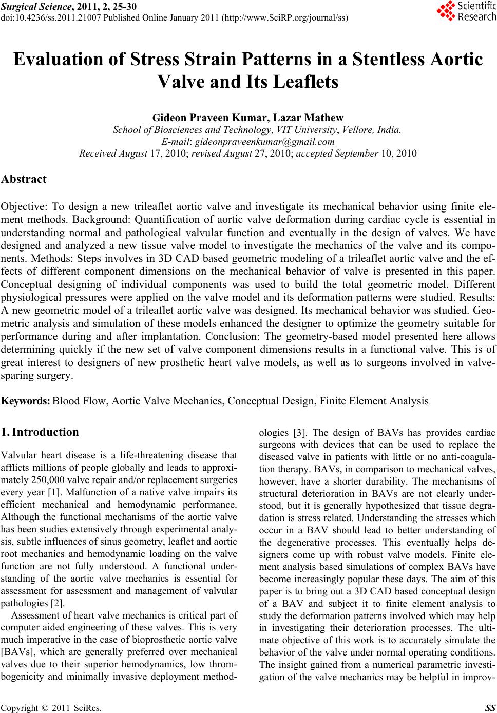 Surgical Science, 2011, 2, 25-30 doi:10.4236/ss.2011.21007 Published Online January 2011 (http://www.SciRP.org/journal/ss) Copyright © 2011 SciRes. SS Evaluation of Stress Strain Patterns in a Stentless Aortic Valve and Its Leaflets Gideon Praveen Kumar, Lazar Mathew School of Biosciences an d Technology, VIT University, Vellore, India. E-mail: gideonpraveenkumar@gmail.com Received August 17, 2010; revised August 27, 2010; accepted September 10, 2010 Abstract Objective: To design a new trileaflet aortic valve and investigate its mechanical behavior using finite ele- ment methods. Background: Quantification of aortic valve deformation during cardiac cycle is essential in understanding normal and pathological valvular function and eventually in the design of valves. We have designed and analyzed a new tissue valve model to investigate the mechanics of the valve and its compo- nents. Methods: Steps involves in 3D CAD based geometric modeling of a trileaflet aortic valve and the ef- fects of different component dimensions on the mechanical behavior of valve is presented in this paper. Conceptual designing of individual components was used to build the total geometric model. Different physiological pressures were applied on the valve model and its deformation patterns were studied. Results: A new geometric model of a trileaflet aortic valve was designed. Its mechanical behavior was studied. Ge o- metric analysis and simulation of these models enhanced the designer to optimize the geometry suitable for performance during and after implantation. Conclusion: The geometry-based model presented here allows determining quickly if the new set of valve component dimensions results in a functional valve. This is of great interest to designers of new prosthetic heart valve models, as well as to surgeons involved in valve- sparing surgery. Keywords: Blood Flow, Aortic Valve Mechanics, Conceptual Design, Finite Element Analysis 1. Introduction Valvular heart disease is a life-threatening disease that afflicts millions of people globally and leads to approxi- mately 250,000 valve repair and/or replacement surgeries every year [1]. Malfunction of a native valve impairs its efficient mechanical and hemodynamic performance. Although the functional mechanisms of the aortic valve has been studies extensively through experimental analy- sis, subtle influences of sinus geometry, leaflet and aortic root mechanics and hemodynamic loading on the valve function are not fully understood. A functional under- standing of the aortic valve mechanics is essential for assessment for assessment and management of valvular pathologies [2]. Assessment of heart valve mechanics is critical part of computer aided engineering of these valves. This is very much imperative in the case of bioprosthetic aortic valve [BAVs], which are generally preferred over mechanical valves due to their superior hemodynamics, low throm- bogenicity and minimally invasive deployment method- ologies [3]. The design of BAVs has provides cardiac surgeons with devices that can be used to replace the diseased valve in patients with little or no anti-coagula- tion therapy. BAVs, in comparison to mechanical valves, however, have a shorter durability. The mechanisms of structural deterioration in BAVs are not clearly under- stood, but it is generally hypothesized that tissue degra- dation is stress related. Understand ing the stresses which occur in a BAV should lead to better understanding of the degenerative processes. This eventually helps de- signers come up with robust valve models. Finite ele- ment analysis based simulations of complex BAVs have become increasingly popular these days. The aim of this paper is to bring out a 3D CAD based conceptual design of a BAV and subject it to finite element analysis to study the deformation patterns involved which may help in investigating their deterioration processes. The ulti- mate objective of this work is to accurately simulate the behavior of the valve under normal operating conditions. The insight gained from a numerical parametric investi- gation of the valve mechanics may be h elpful in improv- 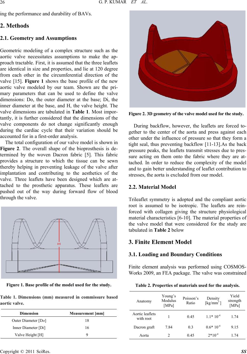 G. P. KUMAR ET AL. Copyright © 2011 SciRes. SS 26 ing the performance and durability of BAVs. 2. Methods 2.1. Geometry and Assumptions Geometric modeling of a complex structure such as the aortic valve necessitates assumptions to make the ap- proach tractable. First, it is assumed that the three leaflets are identical in size and properties, and lie at 120 degree from each other in the circumferential direction of the valve [15]. Figure 1 shows the base profile of the new aortic valve modeled by our team. Shown are the pri- mary parameters that can be used to define the valve dimensions: Do, the outer diameter at the base; Di, the inner diameter at the base, and H, the valve height. The valve dimensions are tabulated in Table 1. Most impor- tantly, it is further considered that the dimensions of the valve components do not change significantly enough during the cardiac cycle that their variation should be accounted for in a first-order analysis. The total configuration of our valv e model is shown in Figure 2. The overall shape of the bioprosthesis is de- termined by the woven Dacron fabric [5]. This fabric provides a structure to which the tissue can be sewn thereby helping in preventing leakage of the valve after implantation and contributing to the aesthetics of the valve. Three leaflets have been designed which are at- tached to the prosthetic apparatus. These leaflets are pushed out of the way during forward flow of blood through the valve. Figure 1. Base profile of the model used for the study. Table 1. Dimensions (mm) measured in commissure based aortic valve. Dimension Measurement [mm] Outer Diameter [Do] 18 Inner Diameter [Di] 16 Valve Height [H] 9 Figure 2. 3D geometry of the valve model used for the study. During backflow, however, the leaflets are forced to- gether to the center of the aorta and press against each other under the influence of pressure so that they form a tight seal, thus preventing backflow [11-13].As the back pressure peaks, the leaflets transmit stresses due to pres- sure acting on them onto the fabric where they are at- tached. In order to reduce the complexity of the model and to gain better understanding of leaflet contribution to stresses, the aorta is excluded from our model. 2.2. Material Model Trileaflet symmetry is adopted and the compliant aortic root is assumed to be isotropic. The leaflets are rein- forced with collagen giving the structure physiological material characteristics [6-10]. The material properties of the valve model that were considered for the study are tabulated in Table 2 below 3. Finite Element Model 3.1. Loading and Boundary Conditions Finite element analysis was performed using COSMOS- Works 2009, an FEA package. The valve was constrained Table 2. Properties of materials used for the analysis. Anatomy Young’s Modulus [MPa] Poisson’s Ratio Density [kg/mm3 ] Yield strength [MPa] Aortic leaflets with root 1 0.45 1.1* 10-4 1.74 Dacron graft 7.84 0.3 0.6* 10-4 9.15 Aorta 2 0.45 2*10-4 1.74 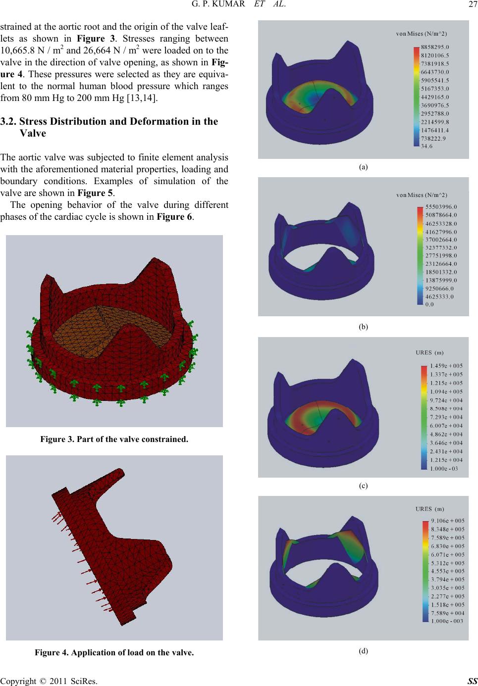 G. P. KUMAR ET AL. Copyright © 2011 SciRes. SS 27 strained at the aortic root and the origin of the valve leaf- lets as shown in Figure 3. Stresses ranging between 10,665.8 N / m2 and 26,664 N / m2 were loaded on to the valve in the direction of valve opening, as shown in Fig- ure 4. These pressures were selected as they are equiva- lent to the normal human blood pressure which ranges from 80 mm Hg to 200 mm Hg [13,14]. 3.2. Stress Distribution and Deformation in the Valve The aortic valve was subjected to finite element analysis with the aforemen tioned material properties, loading an d boundary conditions. Examples of simulation of the valve are shown in Figure 5. The opening behavior of the valve during different phases of the cardiac cycle is shown in Figure 6. Figure 3. Part of the valve constrained. Figure 4. Application of load on the valve. (a) (b) (c) (d) 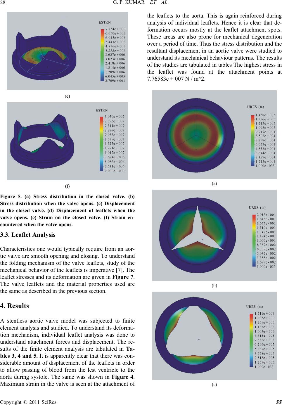 G. P. KUMAR ET AL. Copyright © 2011 SciRes. SS 28 (e) (f) Figure 5. (a) Stress distribution in the closed valve, (b) Stress distribution when the valve opens. (c) Displacement in the closed valve. (d) Displacement of leaflets when the valve opens. (e) Strain on the closed valve. (f) Strain en- countered when the valve opens. 3.3. Leaflet Analysis Characteristics one would typically require from an aor- tic valve are smooth opening and closing. To understand the folding mechanism of the valve leaflets, study of the mechanical behavior of the leaflets is imperative [7]. The leaflet stresses and its deformation are given in Figure 7. The valve leaflets and the material properties used are the same as described in the previous section. 4. Results A stentless aortic valve model was subjected to finite element analysis and studied. To understand its deforma- tion mechanism, individual leaflet analysis was done to understand attachment forces and displacement. The re- sults of the finite element analysis are tabulated in Ta- bles 3, 4 and 5. It is apparently clear that there was con- siderable amount of displacement of the leaflets in order to allow passing of blood from the lest ventricle to the aorta during systole. The same was shown in Figure 4. Maximum strain in the valve is seen at the attach ment of the leaflets to the aorta. This is again reinforced during analysis of individual leaflets. Hence it is clear that de- formation occurs mostly at the leaflet attachment spots. These areas are also prone for mechanical degeneration over a period of time. Thus the stress distribution and the resultant displacement in an aortic valve were studied to understand its mechanical behaviour patterns. The results of the studies are tabulated in tables Th e highest stress in the leaflet was found at the attachment points at 7.76583e + 007 N / m^2. (a) (b) (c) 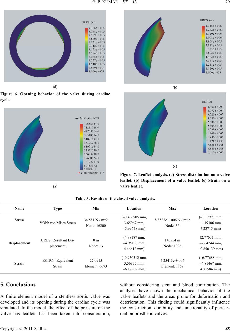 G. P. KUMAR ET AL. Copyright © 2011 SciRes. SS 29 (d) Figure 6. Opening behavior of the valve during cardiac cycle. (a) (b) (c) Figure 7. Leaflet analysis. (a) Stress distribution on a valve leaflet. (b) Displacement of a valve leaflet. (c) Strain on a valve leaflet. Table 3. Results of the closed valve analysis. Name Type Min Location Max Location Stress VON: von Mises Stress 34.581 N / m^2 Node: 16200 (–0.466905 mm, 3.65967 mm, –5.99678 mm) 8.8583e + 006 N / m^2 Node: 36 (–1.17998 mm, –4.49306 mm, 7.23715 mm) Displacement URES: Resultant Dis- placement 0 m Node: 13 (4.88187 mm, –4.95196 mm, 4.46612 mm) 145854 m Node: 1096 (2.77631 mm, –2.64244 mm, –0.850139 mm) Strain ESTRN: Equivalent Strain 27.0915 Element: 6673 (–0.950312 mm, 3.56835 mm, –6.17908 mm) 7.25413e + 006 Element: 1159 (–6.77688 mm, –4.81467 mm, 4.71584 mm) 5. Conclusions A finite element model of a stentless aortic valve was developed and its opening during the cardiac cycle was simulated. In the model, the effect of the pressure on the valve has leaflets has been taken into consideration, without considering stent and blood contribution. The analyses have shown the mechanical behavior of the valve leaflets and the areas prone for deformation and deterioration. This finding could significantly influence the construction, durability and functionality of pericar- dial bioprosthetic valves. 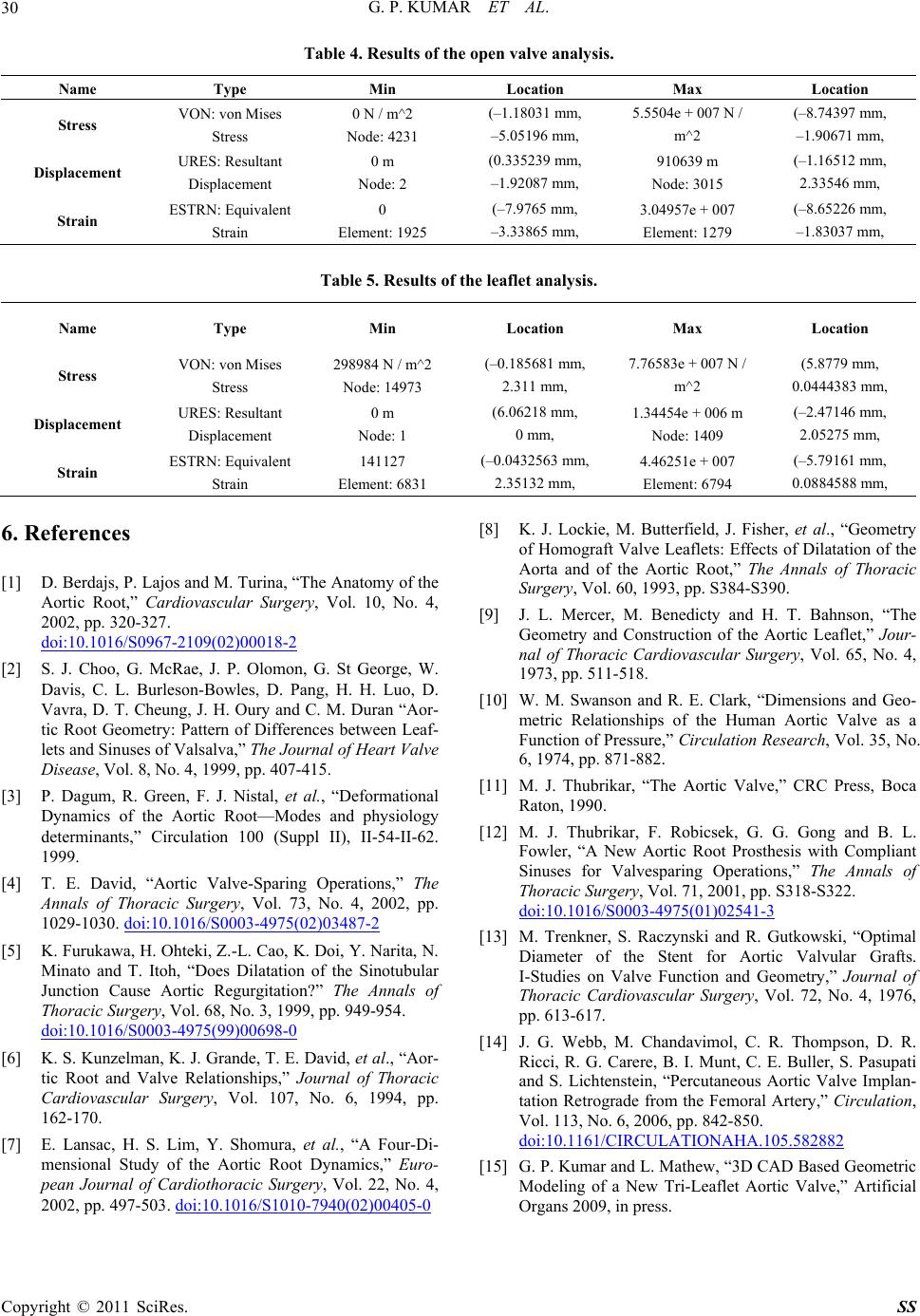 G. P. KUMAR ET AL. Copyright © 2011 SciRes. SS 30 Table 4. Results of the open valve analysis. Name Type Min Location Max Location Stress VON: von Mises Stress 0 N / m^2 Node: 4231 (–1.18031 mm, –5.05196 mm, 5.5504e + 007 N / m^2 (–8.74397 mm, –1.90671 mm, Displacement URES: Resultant Displacement 0 m Node: 2 (0.335239 mm, –1.92087 mm, 910639 m Node: 3015 (–1.16512 mm, 2.33546 mm, Strain ESTRN: Equivalent Strain 0 Element: 1925 (–7.9765 mm, –3.33865 mm, 3.04957e + 007 Element: 1279 (–8.65226 mm, –1.83037 mm, Table 5. Results of the leaflet analysis. Name Type Min Location Max Location Stress VON: von Mises Stress 298984 N / m^2 Node: 14973 (–0.185681 mm, 2.311 mm, 7.76583e + 007 N / m^2 (5.8779 mm, 0.0444383 mm, Displacement URES: Resultant Displacement 0 m Node: 1 (6.06218 mm, 0 mm, 1.34454e + 006 m Node: 1409 (–2.47146 mm, 2.05275 mm, Strain ESTRN: Equivalent Strain 141127 Element: 6831 (–0.0432563 mm, 2.35132 mm, 4.46251e + 007 Element: 6794 (–5.79161 mm, 0.0884588 mm, 6. References [1] D. Berdajs, P. Lajos and M. Turina, “The Anatomy of the Aortic Root,” Cardiovascular Surgery, Vol. 10, No. 4, 2002, pp. 320-327. doi:10.1016/S0967-2109(02)00018-2 [2] S. J. Choo, G. McRae, J. P. Olomon, G. St George, W. Davis, C. L. Burleson-Bowles, D. Pang, H. H. Luo, D. Vavra, D. T. Cheung, J. H. Oury and C. M. Duran “Aor- tic Root Geometry: Pattern of Differences between Leaf- lets and Sinuses of Valsalva,” The Journal of Heart Valve Disease, Vol. 8, No. 4, 1999, pp. 407-415. [3] P. Dagum, R. Green, F. J. Nistal, et al., “Deformational Dynamics of the Aortic Root—Modes and physiology determinants,” Circulation 100 (Suppl II), II-54-II-62. 1999. [4] T. E. David, “Aortic Valve-Sparing Operations,” The Annals of Thoracic Surgery, Vol. 73, No. 4, 2002, pp. 1029-1030. doi:10.1016/S0003-4975(02)03487-2 [5] K. Furukawa, H. Ohteki, Z.-L. Cao, K. Doi, Y. Narita, N. Minato and T. Itoh, “Does Dilatation of the Sinotubular Junction Cause Aortic Regurgitation?” The Annals of Thoracic Surgery, Vol. 68, No. 3, 1999, pp. 949-954. doi:10.1016/S0003-4975(99)00698-0 [6] K. S. Kunzelman, K. J. Grande, T. E. David, et al., “Aor- tic Root and Valve Relationships,” Journal of Thoracic Cardiovascular Surgery, Vol. 107, No. 6, 1994, pp. 162-170. [7] E. Lansac, H. S. Lim, Y. Shomura, et al., “A Four-Di- mensional Study of the Aortic Root Dynamics,” Euro- pean Journal of Cardiothoracic Surgery, Vol. 22, No. 4, 2002, pp. 497-503. doi:10.1016/S1010-7940(02)00405-0 [8] K. J. Lockie, M. Butterfield, J. Fisher, et al., “Geometry of Homograft Valve Leaflets: Effects of Dilatation of the Aorta and of the Aortic Root,” The Annals of Thoracic Surgery, Vol. 60, 1993, pp. S384-S390. [9] J. L. Mercer, M. Benedicty and H. T. Bahnson, “The Geometry and Construction of the Aortic Leaflet,” Jour- nal of Thoracic Cardiovascular Surgery, Vol. 65, No. 4, 1973, pp. 511-518. [10] W. M. Swanson and R. E. Clark, “Dimensions and Geo- metric Relationships of the Human Aortic Valve as a Function of Pressure,” Circulation Research, Vol. 35, No. 6, 1974, pp. 871-882. [11] M. J. Thubrikar, “The Aortic Valve,” CRC Press, Boca Raton, 1990. [12] M. J. Thubrikar, F. Robicsek, G. G. Gong and B. L. Fowler, “A New Aortic Root Prosthesis with Compliant Sinuses for Valvesparing Operations,” The Annals of Thoracic Surgery, Vol. 71, 2001, pp. S318-S322. doi:10.1016/S0003-4975(01)02541-3 [13] M. Trenkner, S. Raczynski and R. Gutkowski, “Optimal Diameter of the Stent for Aortic Valvular Grafts. I-Studies on Valve Function and Geometry,” Journal of Thoracic Cardiovascular Surgery, Vol. 72, No. 4, 1976, pp. 613-617. [14] J. G. Webb, M. Chandavimol, C. R. Thompson, D. R. Ricci, R. G. Carere, B. I. Munt, C. E. Buller, S. Pasupati and S. Lichtenstein, “Percutaneous Aortic Valve Implan- tation Retrograde from the Femoral Artery,” Circulation, Vol. 113, No. 6, 2006, pp. 842-850. doi:10.1161/CIRCULATIONAHA.105.582882 [15] G. P. Kumar and L. Mathew, “3D CAD Based Geometric Modeling of a New Tri-Leaflet Aortic Valve,” Artificial Organs 2009, in press. |