Journal of Surface Engineered Materials and Advanced Technology, 2013, 3, 11-17
http://dx.doi.org/10.4236/jsemat.2013.33A003 Published Online September 2013 (http://www.scirp.org/journal/jsemat)
Copyright © 2013 SciRes. JSEMAT
11
Reduced Activation Energy of Iron and Copper Ion Doped
Mullite which Can Be Used as a Substrate in Electronic
Industry
Debasis Roy, Kumaresh Haldar, Biplab Kumar Paul, Alakananda Bhattacharya, Sukhen Das*,
Papiya Nandy
Physics Department, Jadavpur University, Kolkata, India.
Email: *sdasphysics@gmail.com
Received June 6th, 2013; revised July 10th, 2013; accepted July 22nd, 2013
Copyright © 2013 Debasis Roy et al. This is an open access article distributed under the Creative Commons Attribution License,
which permits unrestricted use, distribution, and reproduction in any medium, provided the original work is properly cited.
ABSTRACT
The crystallized mullite composite has been synthesized via sol-gel technique in the presence of transition metal ions
such as iron and copper. The electrical resistivity and activation energy of the composites have been measured and their
variation with concentration of the metal ion has been investigated. The resistivity of doped mullite decreases rapidly in
the shorter temperature range and sharply in the higher temperature range. The decreasing resistivity is due to the 3d
orbital electrons and the concentration of metal ions present. X-ray analysis confirms the presence of metal ions in mul-
lite, which entered in the octahedral site. The Fe2+ and Cu2+ ions will substitute Al3+ ion in the octahedral site of mullite
structure and most probably will be responsible for reducing the resistivity as well as the activation energy. Transition
metal ion doped mullite-based ceramic can be considered as promising material as a substrate in the electronic industry,
because of its reasonable atom density, its low activation characteristics, low thermal expansion coefficient and high
mechanical strength. The present material we have developed has an activation energy of resistivity/band gap energy,
Eg, 1.11 eV at 0.04 M concentration for Cu2+ ion.
Keywords: Nanostructures; Sol-Gel Growth; X-Ray Diffraction; Scanning Electron Microscopy (SEM); Electrical
Conductivity
1. Introduction
Mullite is a material with an important role in the tech-
nology of classical and advanced ceramics due to high
mechanical strength, low dielectric constant, high creep
resistance and low thermal expansion coefficient [1-8].
Mullite based ceramic composites have been continually
gaining importance in the insulator and semiconductor
industry. Mullite formation starts from 1000˚C due to
solid-state reaction between Al2O3 and SiO2 particles
[9-15].
A wide variety of transition metals enter the mullite
structure, Schneider et al. [2-4] has performed a system-
atic study in order to determine the solubility limit of
various transition metal ions, as well as, the location of
the corresponding cations in the structure [2-4,7]. The
incorporation of transition metal ions strongly depends
on their ionic radii and oxidation states, as well as syn-
thesis procedure. Trivalent cations with ionic radii close
to Al3+ can readily be incorporated in mullite structure.
Mullite composites in the presence of various doping
agents modifying the mechanical and chemical properties
have been reported by many authors. However, literature
concerning the activation energy (Eg) of metal ions
doped mullite composites is relatively few [16-22].
This paper deals with the synthesis of mullite compos-
ites doped with varying concentrations of Fe2+ and Cu2+
ions and determines the effect of the same on activation
energy of the composites. The divalent cations (M) with
larger ionic radii rather react with Al2O3 forming MAl2O4
than enter into mullite structure.
The results indicate that the electrical resistivity of the
composite varies from order 1010 ohm-cm at 400˚C to
order 105 ohm-cm at 1300˚C. As the temperature is in-
creasing, the resistivity is decreasing and the activation
energy initially decreases up to 0.04 M and then in-
creases [23-25].
*Corresponding author.
Reduced Activation Energy of Iron and Copper Ion Doped Mullite which Can Be Used as a
Substrate in Electronic Industry
Copyright © 2013 SciRes. JSEMAT
12
2. Experimental
Mullite precursor gels are prepared from aluminium ni-
trate nonahydrate (Al(NO3)3·9H2O) extra pure (Merck,
India), aluminium isopropoxide (Al(-O-i-Pr)3) puriss
(Spectrochem Pvt. Ltd., India.), tetra ethyl orthosilicate
(Si(OC2H5)4), (Merck, Germany), Iron Nitrate
(Fe(NO3)3·9H2O) (MERCK Specialities Pvt. Ltd., India)
and Copper sulphate pentahydrate (CuSO4·5H2O)
(MERCK Specialities Pvt. Ltd., India).
For the preparation of precursor gels for mullite syn-
thesis, Al(-O-i-Pr)3 and Si(OC2H5)4 were added simul-
taneously to 0.5 M solution of Al(NO3)3·9H2O dissolved
in 20 ml of distilled water. The molar ratio of Al(-O-
i-Pr)3/Al(NO3)3·9H2O was 7:2 and mole ratio of Al/Si
was 3:1 [14].
Doped gels were prepared by adding corresponding
metal salt to the original solution in the ratio Al:Si:M,
where M is the concentration of the cobalt salt in molar-
ity. In the final solution, M was varied as M = 0.002 (G1),
0.02 (G2), 0.10 (G3), 0.15 (G4) and 0.2 M (G5) [12,13].
Gel formation was completed after stirring the solution
for 3 hours and ageing the sol overnight at 60˚C. The gel
was then dried at 110˚C and after grinding, it takes the
form of freely flowing powder. The samples were then
pelletized in disc form of 30 mm diameter and 3 mm
thickness and sintered at 400˚C, 800˚C, 1000˚C and
1300˚C for 3 hr in a muffle furnace under air atmosphere
at the heating rate of 10˚C/minute [15,18,24,25].
The fired pellets were then coated by silver paste on
both sides for electrical measurements.
The silver-coated discs were placed in a press-contact
type Teflon holder to minimize leakage resistance from
the holder. The chamber was made vacuum-tight and
properly shielded [23-25].
3. Instrumentation
X-ray Powder Diffractometer of D8, Bruker AXS, Wis-
consin, USA, using Cu Kα radiation (1.5418 Å) and op-
erating at 40 KV with a scan speed of 1 s/step, analyzed
phase identification of the samples sintered at 1000˚C
and 1300˚C.
The characteristic stretching and bending modes of vi-
bration of chemical bonds of a sample can be effectively
evaluated by spectroscopic methods. 1% of the sample
was mixed with spectroscopy grade KBr, pelletized and
analyzed by FTIR spectroscopy (FTIR-8400S, Shima-
dzu).
Electrical resistivity measurements of the sintered gels
were carried out by electrometer. A constant DC voltage
(V) of about 1.5 V was applied from a battery across the
sample. The voltage (V) across the input resistance was
measured by the electrometer.
Morphology of the sintered gels were observed by
Field Emission Scanning Electron Microscope (FESEM,
model JSM 6700F, JEOL Ltd. Tokyo, Japan).
4. Results and Discussion
In the X-ray diffractograms, doped sintered gels shows
considerable enhancement in mullite phase at 1000˚C
and 1300˚C respectively. The sample G0 represents un-
doped mullite and considerable growth of mullite has
been observed at 1000˚C and 1300˚C respectively from
the diffractograms (Figures 1(a) and (b)). The metal
(a) (b)
Figure 1. X-ray diffraction pattern of mullite precursor gels sintered at 1000˚C and 1300˚C containing increasing concentra-
tion of iron and copper ion.
Reduced Activation Energy of Iron and Copper Ion Doped Mullite which Can Be Used as a
Substrate in Electronic Industry
Copyright © 2013 SciRes. JSEMAT
13
cations have positive effect on the growth of mullite
(JCPDS#15-776) [26] and increases with the increase of
concentration of the metal ion at 1000˚C and 1300˚C
upto G3 (Figures 1(a) and (b)). The “mineralizing” effect
of transition metals on phase transformation of mullite is
well documented by other authors [16-18]. Interaction of
the metal ion with the alumina and silica component of the
gel is implicated in accelerated transformation to mullite
phase [16,21,24,25,27]. The mineralizing effect still con-
tinues for the samples G4 and G5 with respect to G0.
From the diffractograms, it was found that with the in-
crease of metal concentration of doped metal, phase
transformation in the composite increases. In the diffrac-
tograms of G3, G4 and G5 samples, apart from mullite,
α-Al2O3 (JCPDS#46-1212) [28] reflections were ob-
served and in G5 other metal phases are observed (Fi gure
1). In the higher doping concentration mullite formation
slightly decreases due to the formation of aluminium
oxide and metal oxides [16].
Characteristic bands at wave numbers are observed
around 560, 730, 840, 1060 and 1130 cm1 (Figures 2(a)
and (b)) [16]. All the characteristic bands of mullite-561
(AlO6), 741 (AlO4), 837 (AlO4), 900 (AlO4-stretching
mode) and 1130 cm1 (Si-O stretching mode) appear in
samples G1, G2, G3, G4 and G5. Vibration modes corre-
sponding to doped metal oxide bonds were observed in
the FTIR spectra.
According to, Ohm’s law the current (I) in the circuit
is
,
I
VR (1)
where V is voltage, I is current, and R is the resistance of
the load, in this case the sample of metal ion doped mul-
lite. Therefore, the resistance (R) of the sample was cal-
culated as
,RVI (2)
In the time of measurement of resistance of each sam-
ple, the voltage of the battery was checked .The ρ resis-
tivity of a material can be calculated using the relation-
ship

,RAl
(3)
where ρ is the material bulk resistivity, l is the sample
length, and A is the sample’s cross-sectional area per-
pendicular to the current flow.
The electrical conductivity of the samples were de-
scribed by the Arrhenius equation as follows
,
E
gkT
e

(4)
where σ is the electrical conductivity given by 1
,
α is a pre-exponential factor, T is the absolute tempera-
ture, k is the Boltzmann constant, and Eg is the material’s
activation energy.
(a)
(b)
Figure 2. FTIR bands of mullite precursor gels sintered at
1000˚C and 1300˚C containing increasing concentration of
iron and copper ion.
The electrical resistivity of the samples were described
as
1,
(5)
where ρ is the material bulk resistivity and σ is the elec-
trical conductivity [23-25].
A plot of log10 ρ versus 1/T·104 was drawn for each
sample at temperatures 400˚C, 800˚C, 1000˚C and
1300˚C (Figures 3(a) and (b)). The plots show a linear
increase with the reciprocal temperature.
From the log10 ρ vs sintering temperature (˚C) curve
(Figures 4(a) and (b)), resistivity decreases with in-
creasing temperature. It has been observed that for con-
Reduced Activation Energy of Iron and Copper Ion Doped Mullite which Can Be Used as a
Substrate in Electronic Industry
Copyright © 2013 SciRes. JSEMAT
14
(a)
(b)
Figure 3. Resistivity (log10 ρ) versus 1/T * 104 graph of mul-
lite precursor gels sintered at 400˚C, 800˚C, 1000˚C and
1300˚C containing increasing concentration of iron and
copper ion.
centration G1 and G2 the resistivity decreases sharply in
the higher temperature range, but in the lower tempera-
ture range G3, G4, G5 decrease rapidly. G1 exhibits the
lowest resistivity 6.57 × 105 cm for Fe2+ and 3.56 × 10⁵
cm for Cu2+. The Fe2+ and Cu2+ ions react with Al2O3
forming metal aluminates and other phases and response-
ble for decreasing resistivity with sintering temperature.
The activation energy of the samples was calculated in
eV unit from the slope of the plot as follows:
5
slope4.6068.6210eV
g
E
 [23-25]. (6)
From the Eg vs concentration curve, Eg decreases with
concentration and becomes minimum at 0.04 M for Cu2+
ion concentration (Figure 5).
The substitution of Al3+ ion in the mullite lattice by
Fe2+ and Cu2+ ion hampered the electro neutrality of the
composite. As a result probably there will be formation
(a)
(b)
Figure 4. Resistivity versus Temperature (˚C) of mullite
precursor gels sintered at 400˚C, 800˚C, 1000˚C and 1300˚C
containing increasing concentration of iron and copper ion.
Figure 5. Activation energy (Eg) vs concentration curve of
mullite precursor gels sintered at 400˚C, 800˚C, 1000˚C and
1300˚C containing increasing concentration of iron and
copper ion.
Reduced Activation Energy of Iron and Copper Ion Doped Mullite which Can Be Used as a
Substrate in Electronic Industry
Copyright © 2013 SciRes. JSEMAT
15
of a hole when Al3+ ion is replaced by Fe2+ and Cu2+ ion
in the mullite structure [23-25]. It was observed that Fe2+
and Cu2+ ion could not substitute Al3+ ion in mullite but
remained there as a cluster. The lowering of resistivity is
due to the 3d orbital electrons and the concentration of
metal ions. The Fe2+ and Cu2+ ion which substituted Al3+
ion in the octahedral site of mullite structure appeared to
be efficient in reducing the resistivity [23-25]. There are
two possibilities of increase of Eg after attaining its
minimum value at 0.04 M for Cu2+, either complete in-
corporation of Cu2+ ion in the mullite structure or disso-
lution of copper ions in the Si-rich glassy phase. The
dissolution of metal ions in the glassy phase should
dominate over the incorporation of metal ions into mul-
lite.
Mullite samples, therefore, behave like nonmetallic
electrical conductors, because their conductivity rises
faster at lower temperature but slows down at higher
temperature.
The morphology of mullite particles with lowest (G1)
and highest (G5) concentrations of Fe2+ and Cu2+ ion sin-
tered at 1000˚C and 1300˚C was investigated by FESEM.
The micrograph for G1 shows almost round particles
of mullite of an average size of 200 nm. Numerous
smaller particles can also be seen along with amorphous
aggregates (Figures 6(a) and (b)) [12,29-31].
G5 samples shows distinct acicular morphology of
mullite crystals of size 600 nm embedded in the matrix
(Figures 7(a) and (b)). The mullite content and crystal-
lization in all the G5 samples were greater than in G1
composites, indicating the catalytic effect of the Fe2+ and
Cu2+ ions [16,24,25].
(a) (b)
Figure 6. FESEM of mullite precursor gels doped with iron and copper ion sample G1 sintered at 1000˚C and 1300˚C.
(a) (b)
Figure 7. FESEM of mullite precursor gels doped with iron and copper ion sample G5 sintered at 1000˚C and 1300˚C.
Reduced Activation Energy of Iron and Copper Ion Doped Mullite which Can Be Used as a
Substrate in Electronic Industry
Copyright © 2013 SciRes. JSEMAT
16
5. Conclusion
Fe2+ and Cu2+ doped mullite composites have been syn-
thesized by the sol-gel technique, their phase evolution;
band gap activation energy has been investigated. The
results showed that with increase in Fe2+ and Cu2+ ion
concentration the crystallization of mullite was enhanced,
which is evident from X-ray diffraction and FESEM of
the composites. The activation energy of resistivity/band
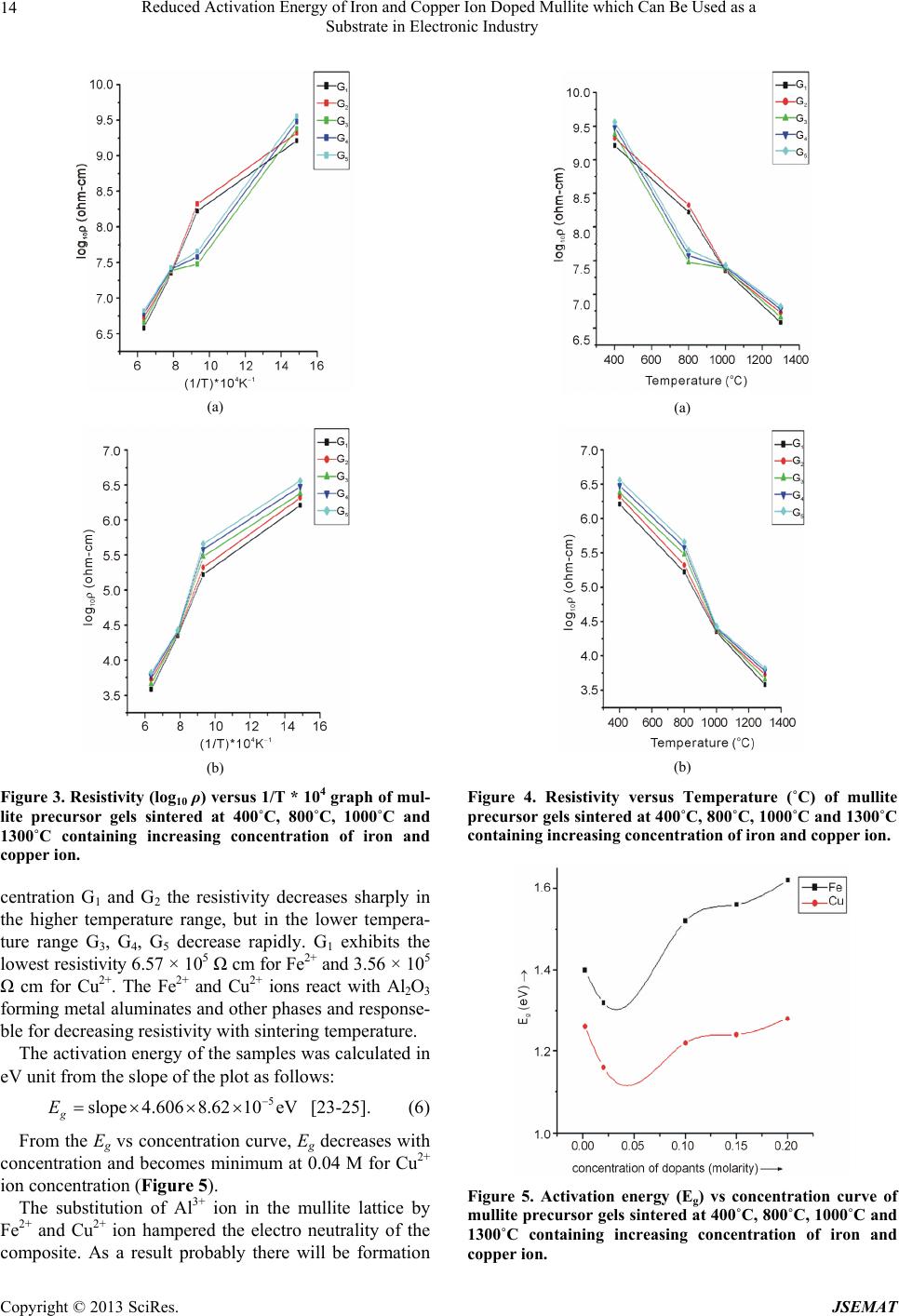
gap energy, Eg, attains a minimum value 1.11 eV at 0.04
M concentration for Cu2+ ion. It has been observed that
the resistivity as well as the band gap energy corresponds
to semiconductors and due to the low activation energy it
can be used as a substrate in the electronic industry.
6. Acknowledgements
We are grateful to the members of the, Department of
Science and Technology and University Grant Commis-
sion (PURSE program), Government of India, for their
assistance.
REFERENCES
[1] I. A. Aksay, D. M. Dabbs and M. Sarikaya, “Mullite for
Structural, Electronic, and Optical Applications,” Journal
of the American Ceramic Society, Vol. 74, No. 10, 1991,
pp. 2343-2358. doi:10.1111/j.1151-2916.1991.tb06768.x
[2] H. Schneider, “Kinetics of Crack Tip Blunting of
Glasses,” Journal of the American Ceramic Society, Vol.
70, No. 1, 1987, pp. 43-48.
doi:10.1111/j.1151-2916.1987.tb04851.x
[3] J. Schreuer, B. Hildmann and H. Schneider, “Elastic
Properties of Mullite Single Crystals up to 1400˚C,”
Journal of the American Ceramic Society, Vol. 89, No. 5,
2006, pp. 1624-1631.
doi:10.1111/j.1551-2916.2006.00921.x
[4] H. Schneider, J. Schreuer and B. Hildmann, “Structure
and Properties of Mullite—A Review,” Journal of the
European Ceramic Society, Vol. 28, No. 2, 2008, pp.
329-344. doi:10.1016/j.jeurceramsoc.2007.03.017
[5] D. S. Perera and G. Allott, “Mullite Morphology in Fired
Kaolinite/Halloysite Clays,” Journal of Materials Science
Letters, Vol. 4, No. 10, 1985, pp. 1270-1372.
doi:10.1007/BF00723478
[6] S. Rahman and S. Freimann, “The Real Structure of Mul-
lite,” In: H. Schneider and S. Komarneni, Eds., Mullite,
Wiley-VCH, Weinheim, 2005.
[7] M. Schmucker and H. Schneider, “Mullite-Type Gels and
Glasses,” In: Schneider and S. Komarneni, Eds., Mullite,
Wiley-VCH, Weinheim, 2005.
[8] V. V. Vol’khin, I. L. Kazakova, P. Pongratz and E. Hal-
wax, “Mullite Formation from Highly Homogeneous
Mixtures of Al2O3 and SiO2,” Inorganic Materials, Vol.
36, No. 4, 2000, pp. 375-379. doi:10.1007/BF02758084
[9] Y. F. Chen, M. C. Wang and M. H. Hon, “Phase Trans-
formation and Growth of Mullite in Kaolin Ceramics,”
Journal of the European Ceramic Society, Vol. 24, No. 8,
2004, pp. 2389-2397.
doi:10.1016/S0955-2219(03)00631-9
[10] F. Sahnoune, M. Chegaar, N. Saheb, P. Goeuriot and F.
Valdivieso, “Algerian Kaolinite Used for Mullite Forma-
tion,” Applied Clay Science, Vol. 38, No. 3-4, 2008, pp.
304-310. doi:10.1016/j.clay.2007.04.013
[11] J. Pascual and J. Zapatero, “Preparation of Mullite
Ceramics from Coprecipitated Aluminum Hydroxide and
Kaolinite Using Hexamethylenediamine,” Journal of the
American Ceramic Society, Vol. 83, No. 11, 2000, pp.
2677-2680. doi:10.1111/j.1151-2916.2000.tb01614.x
[12] Y. F. Tang ,Z. D. Ling ,Y. N. Lu ,A. D. Li, H. Q. Ling ,Y.
J. Wang and Y. Shao, “Study on the Densification of
Composite Coating Particles of α-Al2O3-SiO2,” Materials
Chemistry and Physics, Vol. 75, No. 1-3, 2002, pp. 265-
269. doi:10.1016/S0254-0584(02)00074-3
[13] V. Viswabaskaran, F. D. Gnanama and M. Balasubrama-
nian, “Mullitisation Behaviour of South Indian Clays,”
Ceramics International, Vol. 28, No. 5, 2002, pp. 557-
564. doi:10.1016/S0272-8842(02)00010-X
[14] V. Viswabaskaran, F. D. Gnanama and M. Balasubrama-
nian, “Mullitisation Behaviour of Calcined Clay-Alumina
Mixtures,” Ceramics International, Vol. 29, No. 5, 2003,
pp. 561-571. doi:10.1016/S0272-8842(02)00203-1
[15] V. Viswabaskaran, F. D. Gnanama and M. Balasubrama-
nian, “Mullite from Clay-Reactive Alumina for Insulating
Substrate Application,” Applied Clay Science, Vol. 25,
No. 1-2, 2004, pp. 29-35. doi:10.1016/j.clay.2003.08.001
[16] D. Roy, B. Bagchi, S. Das and P. Nandy, “Electrical and
Dielectric Properties of Sol-Gel Derived Mullite Doped
with Transition Metals,” Materials Chemistry and Phys-
ics, Vol. 138, No. 1, 2013, pp. 375-383.
doi:10.1016/j.matchemphys.2012.11.070
[17] T. Martisius and R. Giraitis, “Influence of Copper Oxide
on Mullite Formation from Kaolinite,” Journal of Mate-
rials Chemistry, Vol. 13, No. 1, 2002, pp. 121-124.
doi:10.1039/b206711k
[18] R. S. Aza, S. J. Moya, T. Epicier and G. Fantozzi, “Im-
proved High-Temperature Mechanical Properties of Zir-
conia-Doped Mullite,” Journal of Materials Science Let-
ters , Vol. 9, No. 12, 1990, pp. 1400-1402.
doi:10.1007/BF00721596
[19] R. Torecillas Imose, Y. Takano, M. Yoshinaka and K. O.
Hirota Yamaguchi, “Novel Synthesis of Mullite Powder
with High Surface Area,” Journal of the American Ce-
ramic Society, Vol. 81, No. 6, 1998, pp. 1537-1540.
doi:10.1111/j.1151-2916.1998.tb02513.x
[20] B. L. Kong, T. S. Zhang, J. Ma and F. Boey, “Some Main
Group Oxides on Mullite Phase Formation and Micro-
structure Evolution,” Journal of Alloys and Compounds,
Vol. 359, No. 1-2, 2003, pp. 292-299.
doi:10.1016/S0925-8388(03)00193-2
[21] B. Bagchi, S. Das, A. Bhattacharya, R. Basu and P.
Nandy, “Nanocrystalline Mullite Synthesis at a Low
Temperature: Effect of Copper Ions,” Journal of the
Reduced Activation Energy of Iron and Copper Ion Doped Mullite which Can Be Used as a
Substrate in Electronic Industry
Copyright © 2013 SciRes. JSEMAT
17
American Ceramic Society, Vol. 92, No. 3, 2009, pp. 748-
751. doi:10.1111/j.1551-2916.2008.02910.x
[22] A. Esharghawi, C. Penot and F. Nardou, “Contribution to
Porous Mullite Synthesis from Clays by Adding Al and
Mg Powders,” Journal of the European Ceramic Society,
Vol. 29, No. 1, 2009, pp. 31-38.
doi:10.1016/j.jeurceramsoc.2008.05.036
[23] S. P. Chaudhuri, S. K. Patra and A. K. Chakraborty,
“Electrical Resistivity of Transition Metal Ion Doped
Mullite,” Journal of the European Ceramic Society, Vol.
19, No. 16, 1999, pp. 2941-2950.
doi:10.1016/S0955-2219(99)00058-8
[24] D. Roy, B. Bagchi, S. Das and P. Nandy, “Electrical Re-
sistivity and Activation Energy of Cobalt Acetate Tetra-
hydrate Doped Mullite,” Ceramic-Silikaty, Vol. 56, No. 3,
2012, pp. 222-228.
[25] D. Roy, B. Bagchi, S. Das and P. Nandy, “Dielectric and
Magnetic Properties of Sol-Gel Derived Mullite-Iron
Nanocomposite,” Journal of Electroceramics, Vol. 28,
No. 4, 2012, pp. 261-267.
doi:10.1007/s10832-012-9725-4
[26] B. L. Kong, T. S. Zhang, J. Ma and F. Boey, “Anisotropic
Grain Growth of Mullite in High-Energy Ball Milled
Powders Doped with Transition Metal Oxides,” Journal
of the European Ceramic Society, Vol. 23, No. 13, 2003,
pp. 2247-2256. doi:10.1016/S0955-2219(03)00048-7
[27] D. Roy, S. Das and P. Nandy, “Possibility of Decreasing
the Activation Energy of Resistivity of Mullite by Doping
with Nickel Ion,” Material Science-Poland, Vol. 30, No.
4, 2012, pp. 406-413. doi:10.2478/s13536-012-0049-5
[28] M. G. Ferreira da Silva “Role of MnO on the Mullitiza-
tion Behavior of Al2O3-SiO2 Gels,” Journal of Sol-Gel
Science and Technology, Vol. 13, No. 1-3, 1998, pp. 987-
990. doi:10.1023/A:1008652129890
[29] E. Tkalcec, J. Kurajica and J. Schmauch, “Crystallization
of Amorphous Al2O3-SiO2 Precursors Doped with
Nickel,” Journal of Non-Crystalline Solids, Vol. 353, No.
30-31, 2007, pp. 2837-2844.
doi:10.1016/j.jnoncrysol.2007.06.011
[30] W. Z. Lv, Q. Qi, F. Wang, S. H. Wei, B. Liu and Z. K.
Luo, “Sonochemical Synthesis of Cobalt Aluminate
Nanoparticles under Various Preparation Parameters,”
Ultrasonics Sonochemistry, Vol. 17, No. 5, 2010, pp.
793-801. doi:10.1016/j.ultsonch.2010.01.018
[31] D. Roy, B. Bagchi, A. Bhattacharya, S. Das and P. Nandy,
“The Influence of Cobalt Acetate on Sol-Gel Derived
Mullite Densification Behaviour,” Journal of Wuhan
University of Technology-Mater. Sci. Ed., Vol. 27, No. 5,
2012, pp. 836-840. doi:10.1007/s11595-012-0558-4