Paper Menu >>
Journal Menu >>
 Journal of Software Engineering and Applications, 2013, 6, 489-499 http://dx.doi.org/10.4236/jsea.2013.69059 Published Online September 2013 (http://www.scirp.org/journal/jsea) 489 Improving Parallelism in Software Development Process Thang N. Nguyen Department of Information Systems, California State University-Long Beach, Long Beach, USA. Email: thang.nguyen@csulb.edu Received July 14th, 2013; revised August 15th, 2013; accepted August 23rd, 2013 Copyright © 2013 Thang N. Nguyen. This is an open access article distributed under the Creative Commons Attribution License, which permits unrestricted use, distribution, and reproduction in any medium, provided the original work is properly cited. ABSTRACT Software development process basically consists of phases, planned and executed in series: 1) feasibility study; 2) re- quirements; 3) design and 4) implementation, prior to production and maintenance. At the end of each phase, there may be an official management decision (go/not go) depending upon cost, time or other reasons. Within each phase or across-phases, parallelism or concurrency can be achieved if modularity and/or independence of functionality exist(s). We propose a different approach to software development process that allows an improved parallel planning and execu- tion of development effort beyond modularity and functionality independen ce. The goal is to shorten development time while possibly cutting cost and maintaining the same intended quality of performance. An example development is sketched. Keywords: Software Development; Parallelism; Concurrency; Software Models 1. Introduction When Gregor Mendel discovered the principle of inheri- tance, basis of genetics, he would not have thought we used it as one of the concepts (in italic) in object-orient- tation, namely abstraction, encapsulation, inheritance, and polymorphism. When Charles Peirce composed the theory of signs, he wouldn’t have thought that we used his concept of icons in window displays. When Christo- pher Alexander, an architect and author of the Nature of Order, he would not have imagined that later he would become the frequent invited speaker at many conferences on object-oriented paradigm, especi ally on design patterns. Applying George Kelly’s personal construct theory with dipole concept in psychoanalysis to diagnose pa- tients to other domains such as exploiting the dipole concept of “in parallel” versus “in series” in software development is more challenging. We do recognize, like Kelly, that most things surrounding us exist as two ends of a dipole: day versus night, good versus bad, and the like. We use, for example, the terms centralization versus decentralization (or convergence versus divergence,) as two opposing ends of a scale, much like a dipole in the sense of George Kelly, in between are possibly various degrees of centralization (or decentralization). They are used in practice in many disciplines, e.g. management strategies, databases, etc. In other cases, parallelism is possible because things “in parallel” occur when they are in different spaces or differen t locations whereas they are in series if they occur in the same space or dimension such as time. For example, in computer science, if multi- ple processors exist then parallel processing as opposed to serial is possible. In so ftware engineering, we consider object-oriented versus procedural as the two flavors of programming paradigms. We can say object-oriented fo- cuses on the object (e.g. icon, class) in the object-verb construct, and procedural on the verb in the verb-object construct, as opposite concepts. However, in software development, the two “in paral- lel” (versus) and “in series” exist conceptually but are not truly opposite. In fact, we actually use a weaker term, concurrency to describe the concurrent executions, e.g. executions by one processor (CPU) and its I/O devices. It would be enticing to investigate the possibility of push- ing the concept of concurrency towards in parallel oppo- site to in series in the domain of software development and management. We propose in this paper a model to further the parallel development of software beyond the concurrency. Figure 1 shows four schemes. Scheme A is the tradi- tional development in series as found in the water fall model per DoD 2167A. Simply speaking there are four phases in water fall development model: feasibility study, requirements (R), design (D) (high-, low-level), and im- plementation (I) to be followed by production and main- tenance (last two phases not shown). Scheme B portraits some development tasks that inherently can be executed Copyright © 2013 SciRes. JSEA 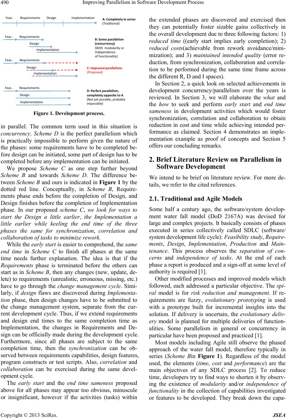 Improving Parallelism in Software Development Process 490 Feas .RequirementsDesignImplementation Feas.Requirements Design Implementation A:Completelyinseries (Traditional) B:Someparallelism (concurrency) (Withmodularityor Independence offunctionality) Feas .Requirements Design Implementation C:Improvedparallelism: (Proposed) Feas .Requirements Desi gn Implementation D:Perfe ctparallelism, completelyoppositetoA (Notyetpossible,probably impossible) Figure 1. Development process. in parallel. The common term used in this situation is concurrency. Scheme D is the perfect parallelism which is practically impossible to perform given the nature of the phases: some requirements have to be completed be- fore design can be initiated, some part of design has to be completed before any implementatio n can be initiated. We propose Scheme C as one step further beyond Scheme B and towards Scheme D. The difference be- tween Scheme B and ours is indicated in Figure 1 by the dotted red line. Conceptually, in Scheme B, Require- ments phase ends before the completion of Design, and Design finishes before the completion of Implementation phase. In our proposed scheme C, we look for ways to start the Design a little earlier, the Implementation a little earlier while keeling the end time of the three phases the same for synchronization, correlation and collaboration of tasks to minimize rework. While the early start is easier to comprehend, the same end time in Scheme C to finish all phases at the same time needs further explanation. The idea is that if the Requirements phase is terminated before the others can start as in Scheme B, then any changes (new, update, de- lete) to requirements (unrealistic, erroneous, missing, etc.) have to go through the change management cycle. Simi- larly, if design flaws are discovered during Implementa- tion phase, then design changes have to be submitted to the change management system, separate from the cur- rent development cycle. Thus, if we extend requirements and design end times to the same completion time as Implementation, the changes in Requirements and De- sign can be officially made during the development cycle. Furthermore, since all phases are subject to the same completion time, then the synchronization can be ob- served between requirements capabilities, design features, program constructs or test scripts. Also, correlation and collaboration can be exercised during the same devel- opment cycle. The early start and the end time sameness proposed above for all phases may appear too obvious, minuscule or insignificant, however if the activities (tasks) within the extended phases are discovered and exercised then they can potentially foster sizable gains collectively in the overall development due to three following factors: 1) reduced time ((early start implies early completion); 2) reduced costs(achievable from rework avoidance/mini- mization); and 3) maintained intended quality (error re- duction, from synchronization, collaboration and correla- tion to be performed during the same time frame across the different R, D and I spaces). In Section 2, a quick look on selected achievements in development concurrency/parallelism over the years is reviewed. In Section 3, we will elaborate the what and the how to seek and perform early start and end time sameness in development activities which would foster synchronization, correlation and collaboration to obtain reduction in cost and time while achieving intended per- formance as claimed. Section 4 demonstrates an imple- mentation example as proof of concepts and Section 5 offers our concluding remarks. 2. Brief Literature Review on Parallelism in Software Development We intend to be brief on literature review. For more de- tails, we refer to the cited references. 2.1. Traditional and Agile Models Some half a century ago, the software/system develop- ment water fall model (DoD 2167A) was devised for large and complex projects. It basically consists of phases executed in series collectively called SDLC (software/ system developm e nt li f e cycle): Feasibility study, Require- ments, Design, Implementation, Production and Main- tenance. This process observes the separation of con- cerns and independence of tasks. At the end of each phase a report is produced and a sign-off at some level of authority is required [1]. Other modified processes and improved models which followed, each addressed a particular objective. The spi- ral model is for risk reduction and management. If re- quirements are fuzzy, evolutionary prototyping is used with a prototype built for incremental insights into the solution. If delivery is uncertain, the evolutionary deliv- ery model is planned for multiple deliveries of function- alities. Some parallelism in general or concurrency in particular have bee n proposed and practice d [1]. Most models including Agile still observe the phased approach of the water fall model, therefore typically in series (Scheme Bin Figure 1). Regardless of the model used, the elements (time, cost and performance) are the main objectives of any SDLC process [2]. To reduce time, developers try to find ways to shorten it by observ- ing the existence of modularity and/or independence of functionality in the collection of capabilities investigated or features to be developed. They break down the capa- Copyright © 2013 SciRes. JSEA  Improving Parallelism in Software Development Process 491 bilities/features into more or less independent modules, and perform the development of these modules concur- rently (Scheme B). In Agile development technology, various Agile mod- els generally include the human factor in a clever way in contrast to traditional models to exploit parallelism. Models such as Rapid Application Development, XP, SCRUM, Crystal, and some well-known practices such as JAD, DSDM, UPs, and others have addressed parallelism in the development tasks at various degrees. In [3], Senad Cimic discussed a possible parallel development in XP, but actually limited it to software configuration manage- ment to accommodate changes. There have been other ways to exercise parallelism in software configuration management [4]. In design phase, discovery of parallel tasks can be identified in UML diagram (agile, object- oriented) or DFD (traditional-procedural, structured) such that some level of parallelism can be addressed [5]. 2.2. Identifying Concepts Leading to Improving Parallelism in Software Development Parallelism has been widely exercised in hardware and in software configuration management as we have men- tioned and referenced in the previous subsection. What we saw in the previous schemes are specific and smaller domains for exploring potential parallelism in R, D or I, and quality assurance as in Agile models. At closer look, we can identify the three concepts of synchronization, collaboration and correlation within each of the R, D and I spaces but not much among or between them. We extend them further with the consideration that humans do most things in parallel within the in series context. An example is visual perception. While the optical sig- nals of perceived object in the visual field of the two eyes combined is processed in series from the retina, to the LGN (lateral geniculate nucleus), to the PVC (primary visual cortex), they actually go through two separate pathways. For our modeling, we list the following prin- ciples governing the visual perception, derived from the work of many researchers including the work of Eric Kandel and David Hubel. They could be used as guiding principles for our proposed work. Some of these princi- ples may overlap. They are listed below, but discussed more in [6]. 1) Principle of vertical integration (summary) primar- ily involving excitatory projection neurons (abstraction, convergence); 2) Principle horizontal integration promoting fine- ness(details) primarily involving inhibitory interneurons, 3) Principle of parallelism of visual pathways; 4) Principle of complementarity on image formulation; 5) Principle of focus (attention) on part of visual memory; 6) Principle of association with different visual memo- ries, and; 7) Principle of recall (recognition) of perceived visual memories. We will apply selectively these principles in the for- mulation of the model described in the next section. 3. Model R: The W’s and The H’s towards Model Formulation for Improving Parallelism In this paper, we break the Implementation (I) phase into Construction (C, or programming) and V&V (testing). Figure 2(a) shows the four phases or major tasks: R, D, C and V&V, each occupies a surface of the solid pyramid representing the entire development work. Flattening the pyramid and reconnecting the vertices a little differently, the representation becomes the collection of four quad- rants in the diagram as problem, solution, construction and V&V spaces in a rhombic shape (Figure 2(b)). Each surface represents its own domain and has its own hierarchy by decomposition (requirements) or by composition (design). Similar hierarchies can be con- structed for programming (construction) and testing (V&V). The vertices denote the Statement of Work (SOW) or business objectives (OBJs) of the software to be de- veloped. This is followed by strategy document. Each domain has its own development strategy for the devel- opment of capabilities (Requirements), features (Design), translated in to the strategy development for correspond- ing program modules (construction) and test script mod- ules (V&V). Showing R, D, C and V&V in this way, we are look- ing at the space dimension, rather than time dimension. Th e fo ur major tasks share the same inter ior (i.e. content), where all details are examined at the same time, at the same level of abstraction. An example follows. In Re- quirements, we commonly start with developing a Re- quirements Definition strategy (how to collect and define the collection of applicable requirements). In the water- fall model, this strategy needs be complete as part of the Requirement Definition document to be signed off by authority before the Design can be started. In our pro- posed model, we attempt to start developing the Design strategy while Requirement Definition Strategy is under way. This illustrates the idea of early start. The four hi- erarchical structures in the rhombic shape also allow us to look at the multiple spaces at the same time for syn- chronization of development effort from start to end in one framework. This is the idea of end time sameness. Within the same scope or at the same level of abstrac- tion, we will try to initiate the analysis (requirements) or synthesis (design), program constructs (programming) or test constructs (V&V). It is true that the sequence R, D, C and V&V in that order still exists. But we explore the possibility for early start of each domain (D, C and V&V) once the do main R is reason ab ly d efined. Details o n wh at Copyright © 2013 SciRes. JSEA  Improving Parallelism in Software Development Process Copyright © 2013 SciRes. JSEA 492 (a) (b) Figure 2. Model R sketch. (a) Perspective view; (b) Modified top view (flattened and reconnected). 3.2. The How and how will be presented next. Within each space, a hierarchical view of each major development is detailed. The four quadrants offer a par- allel view of development activities and show status of all four spaces, hence together a combined view on ver- tical and horizontal integration. It also offers a view for synchronization, collaboration and synchronization of activities and status within each quadrant and across them. Previously known techniques and resulting dia- grams such as UML (objet-oriented), e.g. activity-dia- grams, swimlane-diagram, or DFD diagram (traditionally procedural or structured) can be developed in support of the development of the four hierarchies. Developers can look across all spaces, drill-down for details or roll-up for more abstracted entities. The activities can be traced, combined, synchronized or correlated for detection of gaps or mismatches, missing or duplicate items, etc. 3.1. The What Refer to Figure 3 (which details Figure 2(b)). The quadrants, each corresponds to a major task (or domain) of the development: R, D, C and V&V. They are consid- ered as four different spaces: 1) Top-left quadrant: problem space is where capabili- ties are decomposed by rectangle blocks described in terms of required capabilities, sub-capabilities, etc. 2) Top-right quadrant: solution space in terms of cor- responding design strategy, and designed features/sub- features based on capabilities described as requirements; 3) Bottom-right quadrant: construction space where programming strategy is devised and program modules for features occurs; 4) Bottom-left quadrant: verification and validation (V&V) space where test strategy and all types of tests and levels of tests takes place, and; The seven principles described in human visual proc- ess described earlier can be selectively applied. Further- more these principles are not limited to only internal hu- man physiology. Human behavior in general exercises several of these principles. An example is that in reading (writing) a text or interpreting (composing) a song, al- though one word or one note is expressed at a time from the start to the end, the actual interpretation involves the synchronization, correlation and collaboration among them by the eyes (seeing), the ears (hearing), the facial uscles for perceptions or the limbs movement and for 5) The oval shape in the center of the model crossing all quadrants depicts the documentation activity of all other activities. This set of four quadrants and the documentation oval in the diagram from the top view are detailed by a collection of lower layered-linkable relationships (right in Figure 3) between the tasks at one level to the next levels of details on requirements capabilities from use cases, design features, programming classes, and test cases. m 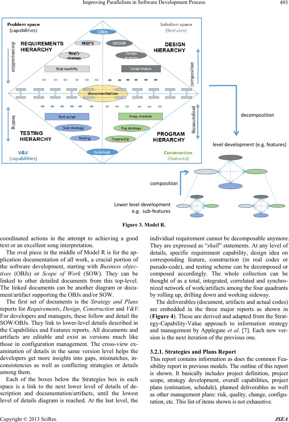 Improving Parallelism in Software Development Process 493 leveldevelopment(e. g.features) Lowerleveldevelopment e.g.sub‐features decomposition composition Figure 3. Model R. coordinated actions in the attempt to achieving a good text or an excellent song interpretation. The oval piece in the middle of Model R is for the ap- plication documentation of all work, a crucial portion of the software development, starting with Business objec- tives (OBJs) or Scope of Work (SOW). They can be linked to other detailed documents from this top-level. The linked documents can be another diagram or docu- ment/artifact supporting the OBJs and/or SOW. The first set of documents is the Strategy and Plans reports for Requirements, Design, Construction and V&V. For developers and managers, these follow and detail the SOW/OBJs. They link to lower-level details described in the Capabilities and Features reports. All documents and artifacts are editable and exist as versions much like those in configuration management. The cross-view ex- amination of details in the same version level helps the developers get more insights into gaps, mismatches, in- consistencies as well as conflicting strategies or details among them. Each of the boxes below the Strategies box in each space is a link to the next lower level of details of de- scription and documentation/artifacts, until the lowest level of details diagram is reached. At the last level, the individual requirement cannot be decomposable anymore. They are expressed as “shall” statements. At any level of details, specific requirement capability, design idea on corresponding feature, construction (in real codes or pseudo-code), and testing scheme can be decomposed or composed accordingly. The whole collection can be thought of as a total, integrated, correlated and synchro- nized network of wo r k/ art i facts among the fou r qua drants by rolling up, drilling down and working sideway. The deliverables (do cument, artifacts and actual co d es) are embedded in the three major reports as shown in (Figure 4). These are derived and adapted from the Strat- egy-Capability-Value approach to information strategy and management by Applegate et al. [7]. Each new ver- sion is the next iteration of the previous one. 3.2.1. Strategies and Plans Report This report contains information as does the common Fea- sibility report in previous models. The outline of this report is shown. It basically includes project definition, project scope, strategy development, overall capabilities, project plans (estimation, schedule), planned deliverables as well as other management plans: risk, quality, change, configu- ration, etc. This list of items shown is not exhaustive. Copyright © 2013 SciRes. JSEA 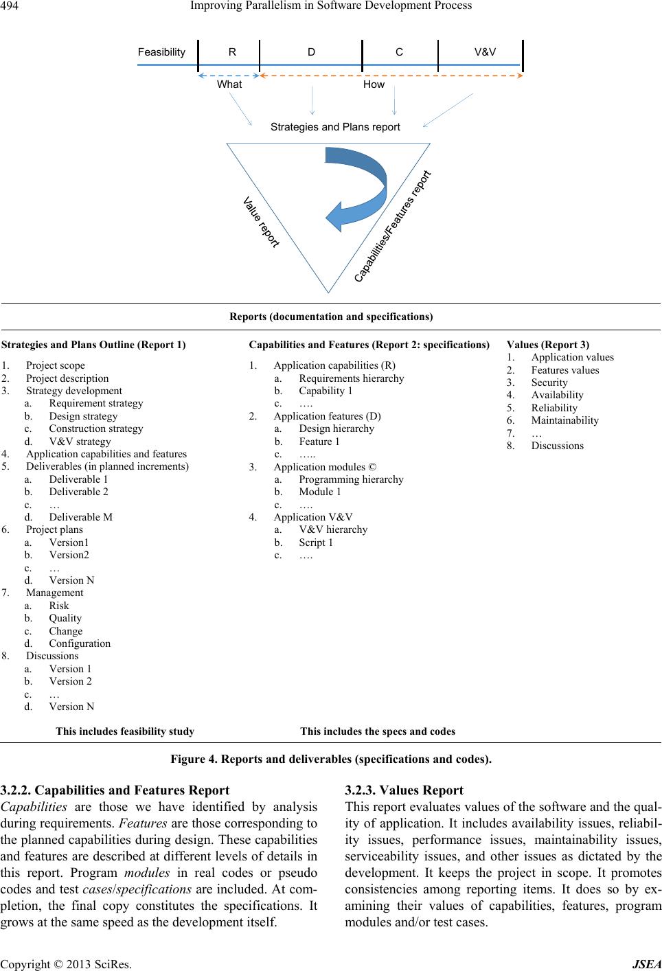 Improving Parallelism in Software Development Process 494 What How RD CV&VFeasibilit y Strategies and Plans report Reports (documentation and specifications) Strategies and Plans Outline (Report 1) 1. Project scope 2. Project description 3. Strategy development a. Requirement strategy b. Design strategy c. Construction strategy d. V&V strategy 4. Application capabilities and features 5. Deliverables (in planned increments) a. Deliverable 1 b. Deliverable 2 c. … d. Deliverable M 6. Project plans a. Version1 b. Version2 c. … d. Version N 7. Management a. Risk b. Quality c. Change d. Configuration 8. Discussions a. Version 1 b. Version 2 c. … d. Version N Capabilities and Features (Report 2: specifications) 1. Application capabilities (R) a. Requirements hierarchy b. Capability 1 c. …. 2. Application features (D) a. Design hierarchy b. Feature 1 c. ….. 3. Application modules © a. Programming hierarchy b. Module 1 c. …. 4. Application V&V a. V&V hierarchy b. Script 1 c. …. Values (Report 3) 1. Application values 2. Features values 3. Security 4. Availability 5. Reliability 6. Maintainability 7. … 8. Discussions This includes feasibility study This includes the specs and codes Figure 4. Reports and deliverables (spe c i fic a tions and c o de s). 3.2.2. Capabilities and Features Report Capabilities are those we have identified by analysis during requirements. Features are those corresponding to the planned capabilities during design. These capabilities and features are described at different levels of details in this report. Program modules in real codes or pseudo codes and test cases/specifications are included. At com- pletion, the final copy constitutes the specifications. It grows at the same speed as the development itself. 3.2.3. V al u es Report This report evaluates values of the software and the qual- ity of application. It includes availability issues, reliabil- ity issues, performance issues, maintainability issues, serviceability issues, and other issues as dictated by the development. It keeps the project in scope. It promotes consistencies among reporting items. It does so by ex- amining their values of capabilities, features, program modules and/or test cases. Copyright © 2013 SciRes. JSEA 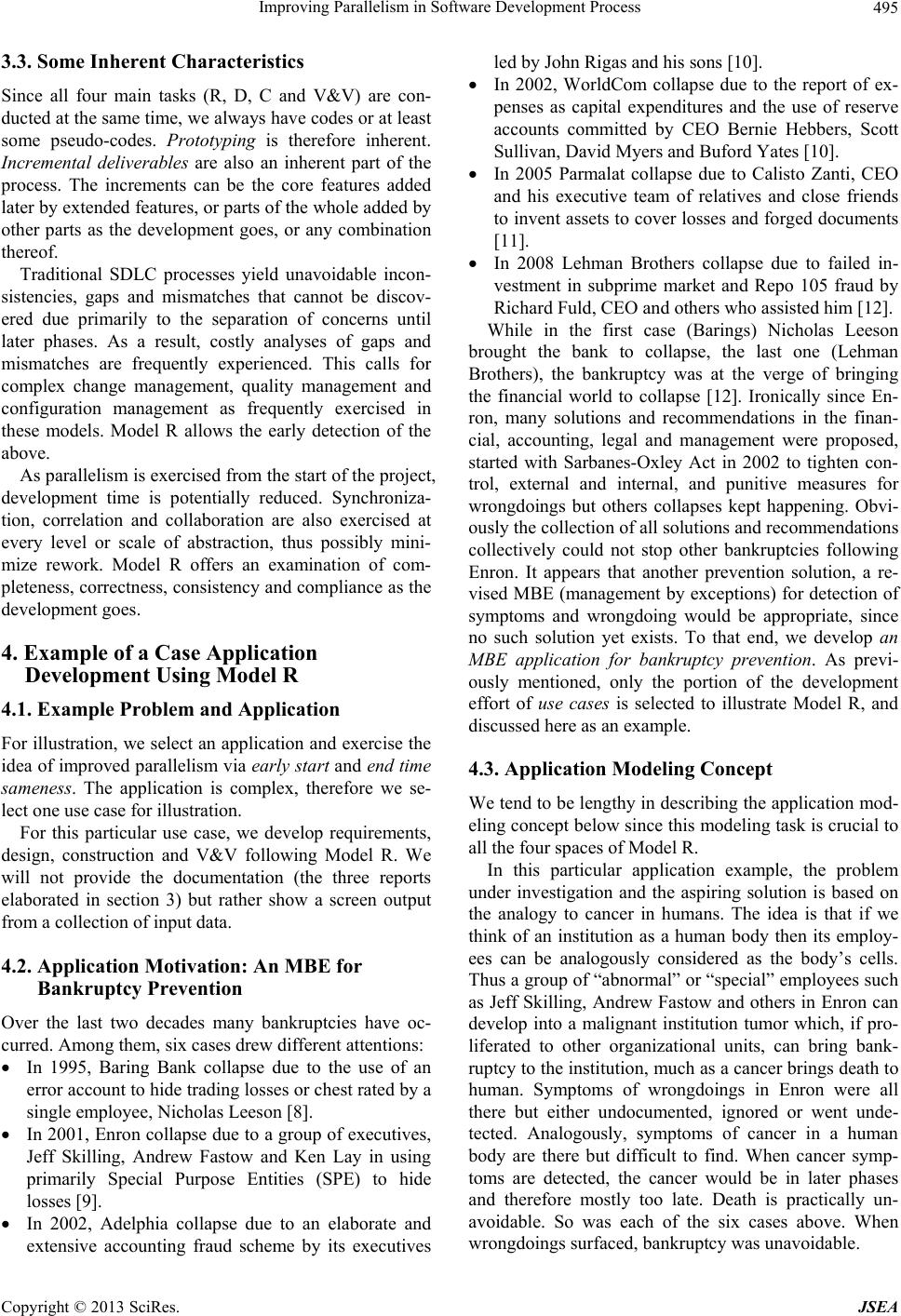 Improving Parallelism in Software Development Process 495 3.3. Some Inherent Characteristics Since all four main tasks (R, D, C and V&V) are con- ducted at the same time, we always have codes or at least some pseudo-codes. Prototyping is therefore inherent. Incremental deliverables are also an inherent part of the process. The increments can be the core features added later by extended features, or parts of the whole added by other parts as the development goes, or any combination thereof. Traditional SDLC processes yield unavoidable incon- sistencies, gaps and mismatches that cannot be discov- ered due primarily to the separation of concerns until later phases. As a result, costly analyses of gaps and mismatches are frequently experienced. This calls for complex change management, quality management and configuration management as frequently exercised in these models. Model R allows the early detection of the above. As parallelism is exercised from the start of the project, development time is potentially reduced. Synchroniza- tion, correlation and collaboration are also exercised at every level or scale of abstraction, thus possibly mini- mize rework. Model R offers an examination of com- pleteness, correctness, consistency and compliance as the development goes. 4. Example of a Case Application Development Using Model R 4.1. Example Problem and Application For illustration, we select an application and exercise the idea of improved parallelism via early s tart and end tim e sameness. The application is complex, therefore we se- lect one use case for illustration. For this particular use case, we develop requirements, design, construction and V&V following Model R. We will not provide the documentation (the three reports elaborated in section 3) but rather show a screen output from a collection of input data. 4.2. Application Motivation: An MBE for Bankruptcy Prevention Over the last two decades many bankruptcies have oc- curred. Among them, six cases drew different attentions: In 1995, Baring Bank collapse due to the use of an error account to hide trading losses or chest rated by a single employee, Nicholas Leeson [8]. In 2001, Enro n collapse due to a group of execu tives, Jeff Skilling, Andrew Fastow and Ken Lay in using primarily Special Purpose Entities (SPE) to hide losses [9]. In 2002, Adelphia collapse due to an elaborate and extensive accounting fraud scheme by its executives led by John Rigas and his sons [10]. In 2002, WorldCom collapse due to the report of ex- penses as capital expenditures and the use of reserve accounts committed by CEO Bernie Hebbers, Scott Sullivan, David Myers and Buford Yates [10]. In 2005 Parmalat collapse due to Calisto Zanti, CEO and his executive team of relatives and close friends to invent assets to cover losses and forged documents [11]. In 2008 Lehman Brothers collapse due to failed in- vestment in subprime market and Repo 105 fraud by Richard Fuld, CEO and others who assisted him [12]. While in the first case (Barings) Nicholas Leeson brought the bank to collapse, the last one (Lehman Brothers), the bankruptcy was at the verge of bringing the financial world to collapse [12]. Ironically since En- ron, many solutions and recommendations in the finan- cial, accounting, legal and management were proposed, started with Sarbanes-Oxley Act in 2002 to tighten con- trol, external and internal, and punitive measures for wrongdoings but others collapses kept happening. Obvi- ously the collection of all solutions and recommendations collectively could not stop other bankruptcies following Enron. It appears that another prevention solution, a re- vised MBE (management by exceptions) for detection of symptoms and wrongdoing would be appropriate, since no such solution yet exists. To that end, we develop an MBE application for bankruptcy prevention. As previ- ously mentioned, only the portion of the development effort of use cases is selected to illustrate Model R, and discussed here as an example. 4.3. Application Modeling Concept We tend to be lengthy in describing the application mod- eling concept b elow since this modeling task is cru cial to all the four spaces of Model R. In this particular application example, the problem under investigation and the aspiring solution is based on the analogy to cancer in humans. The idea is that if we think of an institution as a human body then its employ- ees can be analogously considered as the body’s cells. Thus a group of “abnormal” or “special” employees such as Jeff Skilling, Andrew Fastow and others in Enron can develop into a malignant institution tumor which, if pro- liferated to other organizational units, can bring bank- ruptcy to the institution, much as a cancer brings death to human. Symptoms of wrongdoings in Enron were all there but either undocumented, ignored or went unde- tected. Analogously, symptoms of cancer in a human body are there but difficult to find. When cancer symp- toms are detected, the cancer would be in later phases and therefore mostly too late. Death is practically un- avoidable. So was each of the six cases above. When wrongdoings surfaced, bankruptcy was unavoidable. Copyright © 2013 SciRes. JSEA 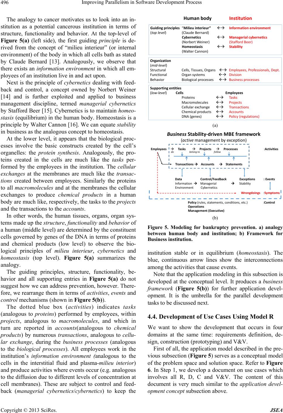 Improving Parallelism in Software Development Process 496 The analogy to cancer motivates us to look into an in- stitution as a potential cancerous institution in terms of structure, functionality and behavior. At the top-level of Figure 5(a) (left side), the first guiding principle is de- rived from the concept of “milieu interieur” (or internal environment) of the body in which all cells bath as stated by Claude Bernard [13]. Analogously, we observe that there exists an info rmation environment in which all em- ployees of an institution liv e in and act upon. Next is the principle of cybernetics dealing with feed- back and control, a concept owned by Norbert Weiner [14] and is further exploited and applied to business management discipline, termed managerial cybernetics by Stafford Beer [15]. Cybernetics is to maintain homeo- stasis (equilibrium) in the human bo dy. Homeostasis is a principle by Walter Cannon [16]. We can equate stability in business as the analog ous concept to homeostasis. At the lower level, it appears that the biological proc- esses involve the basic constructs created by the cell’s organelles: the protein synthesis. Analogously, the pro- teins created in the cells are much like the tasks per- formed by the employees in the institution. The cellular exchanges at the membranes are much like the transac- tions created between employees. Similarly the proteins to all macromolecules and at the membranes the cellular exchanges to produce chemical products in a human body are much like, respectively, the tasks to the projects and the transactions to the accounts. In other words, the human tissues, organs, organ sys- tems made up the structure, functionality and behavior of a human (middle level) are determined by the constitu ent cells governed by genes of the DNA in terms of proteins and chemical products (low level) to observe the bio- logical principles of milieu interieur, cybernetics and homeostasis (top level). Figure 5(a) summarizes the analogy. The guiding principles, structure, functionality, be- havior and all supporting entries in Figure 5(a) do not suggest how we can address preven tion, how ever. There- fore, we rearrange them in terms of activities, events and control mechanisms (shown in Figure 5(b)). The dotted blue box (activities) indicates tasks (analogous to proteins) performed by employees, within projects, analogous to macromolecules, and which in turn are reported in accounts(analogous to chemical products) by numerous transactions, analogous to cellu- lar exchange, during the business processes (analogous to the biological processes). All employees work in the institution’s information environment (analogous to the cells in the interstitial fluid and plasma-milieu interior) and produce activities where events occur (e.g. analogous to the diffusion du e to different levels of con centration at cell membranes). These are subject to control and feed- back (managerial cybernetics/cybernetics) to keep the Humanbody Institution Guidingprinciples “Milieuinterieur” Informationenvironment Managerialcybernetics (StaffordBeer) Stability (toplevel) (ClaudeBernard) Cybernetics (NorbertWeiner ) Homeostasis (WalterCannon) Organization (mid‐level) Structural Cells,Tissues,Organs FunctionalOrgansystems Behavior Biologicalprocesses Employees,Professionals,Dept. Division Businessprocesses Supportingentities (low‐level)Cells Employees Proteins Macromolecules Cellularexchange Chemicalproducts DNA(genes) Tas ks Projects Transactions Accounts Policy(regulations) (a) Employees Tasks Projects Processes :Activities do belongtofollow BusinessStability‐drivenMBEframework (active managementbyexception) TransactionsAccountsStatements Data Control/FeedbackExceptions :Events InformationManagerial Stability EnvironmentCybernetics Wrongdoings :Symptoms Policy (rules,statements,conditions,etc.):Control Operations Management(Executive) (b) Figure 5. Modeling for bankruptcy prevention. a) analogy between human body and institution; b) Framework for Business institution. institution stable or in equilibrium (homeostas is). The blue, continuous arrow lines show the interconnections among the activities that cause ev ents. Note that the application modelin g in this sub section is developed at the conceptual level. It produces a business framework (Figure 5(b)) for further application devel- opment. It is the umbrella for the parallel development tasks to be discussed next. 4.4. Development of Use Cases Using Model R We want to show the development that occurs in four domains at the same time: requirements definition, de- sign, construction (prototyping) and V&V. First of all, the application model described in the pre- vious subsection (Figure 5) serves as a conceptual model of the problem space and solution space. Refer to Figure 6. In Step 1, we develop a document on use cases which involves all R, D, C and V&V. The content of this document is very much similar to the application devel- pment concept subsection above. o Copyright © 2013 SciRes. JSEA 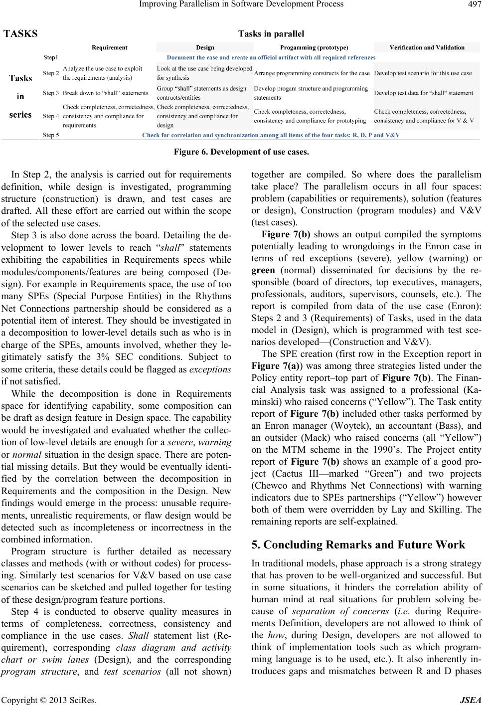 Improving Parallelism in Software Development Process Copyright © 2013 SciRes. JSEA 497 Figure 6. Development of use cases. In Step 2, the analysis is carried out for requirements definition, while design is investigated, programming structure (construction) is drawn, and test cases are drafted. All these effort are carried out within the scope of the selected use cases. Step 3 is also done across the board. Detailing the de- velopment to lower levels to reach “shall” statements exhibiting the capabilities in Requirements specs while modules/components/features are being composed (De- sign). For example in Requirements space, the use of too many SPEs (Special Purpose Entities) in the Rhythms Net Connections partnership should be considered as a potential item of interest. They should be investigated in a decomposition to lower-level details such as who is in charge of the SPEs, amounts involved, whether they le- gitimately satisfy the 3% SEC conditions. Subject to some criteria, these details could be flagged as exceptions if not satisfied. While the decomposition is done in Requirements space for identifying capability, some composition can be draft as design feature in Design space. The capab ility would be investigated and evaluated whether the collec- tion of low-level details are enough for a severe, warning or norm a l situation in the design space. There are poten- tial missing details. But they would be eventually identi- fied by the correlation between the decomposition in Requirements and the composition in the Design. New findings would emerge in the process: unusable require- ments, unrealistic requirements, or flaw design would be detected such as incompleteness or incorrectness in the combined information. Program structure is further detailed as necessary classes and methods (with or without codes) for process- ing. Similarly test scenarios for V&V based on use case scenarios can be sketched and pulled together for testing of these design/program feature portions. Step 4 is conducted to observe quality measures in terms of completeness, correctness, consistency and compliance in the use cases. Shall statement list (Re- quirement), corresponding class diagram and activity chart or swim lanes (Design), and the corresponding program structure, and test scenarios (all not shown) together are compiled. So where does the parallelism take place? The parallelism occurs in all four spaces: problem (capabilities or requirements), solution (features or design), Construction (program modules) and V&V (test cases). Figure 7(b) shows an output compiled the symptoms potentially leading to wrongdoings in the Enron case in terms of red exceptions (severe), yellow (warning) or green (normal) disseminated for decisions by the re- sponsible (board of directors, top executives, managers, professionals, auditors, supervisors, counsels, etc.). The report is compiled from data of the use case (Enron): Steps 2 and 3 (Requirements) of Tasks, used in the data model in (Design), which is programmed with test sce- narios developed—(Construction and V&V). The SPE creation (first row in the Exception report in Figure 7(a)) was among three strategies listed under the Policy entity report–top part of Figure 7(b). The Finan- cial Analysis task was assigned to a professional (Ka- minski) who raised con cerns (“Yellow”). The Task en tity report of Figure 7(b) included other tasks performed by an Enron manager (Woytek), an accountant (Bass), and an outsider (Mack) who raised concerns (all “Yellow”) on the MTM scheme in the 1990’s. The Project entity report of Figure 7(b) shows an example of a good pro- ject (Cactus III—marked “Green”) and two projects (Chewco and Rhythms Net Connections) with warning indicators due to SPEs partnerships (“Yellow”) however both of them were overridden by Lay and Skilling. The remaining reports are self-explained. 5. Concluding Remarks and Future Work In traditional models, phase approach is a strong strategy that has proven to be well-organized and successful. But in some situations, it hinders the correlation ability of human mind at real situations for problem solving be- cause of separation of concerns (i.e. during Require- ments Definition, developers are not allowed to think of the how, during Design, developers are not allowed to think of implementation tools such as which program- ming language is to be used, etc.). It also inherently in- troduces gaps and mismatches between R and D phases  Improving Parallelism in Software Development Process 498 (a) (b) Figure 7. Application output and inputs. (a) Output (exceptions list); (b) Inputs (symptoms list-combined). that can be only discovered at a later time among other problems discussed earlier. Agile development strategy approaches this situation in an elegant way but it does not take full advantage of human intellectual spectrum of integration and correla- tion. Scope is smaller for development control and qual- ity assurance. The parallelism of the proposed model stems on the basic fact that human can do many complex tasks at the same time and human ability can be exploited to the full extent. The Model R offers the unique opportunity for developers to exercise their human ability in identifying potentials for parallelism. The parallelism is performed by considering that the phases are different (but relevant) spaces during the same period of time. The initial scheme in this approach is early start and end time sameness for improvement of parallelism, therefore cost and time re- duce. We do not provide cost-benefits analysis or CPM/PERT to measure the savings in cost or time. A more thorough investigation is necessary to push the par- allelism further. Note that the Model R assumes that developers are experienced in development for exercising synchroniza- tion, correlation and/or collaboration. Furthermore, two challenges arise from the basic nature of the model: 1) higher complexity and 2) updates to the existing SOP for application development, including the documentation reports. These are topics of our future research. REFERENCES [1] R. Pressman, “Software Engineering: A Practitioner’s Ap- proach,” 7th Edition, McGraw-Hill Science/Engineering/ Math, Boston, 2010. [2] S. Cimic, “Applying Agility to the Parallel Software De- velopment Lifecycle,” Proceedings of Midwest Instruc- tion and Computing Symposium, April 2007. [3] Software Methodologies, 2013. http://softwaremethodologies.blogspot.com/2009/04/adva ntages-disadvantages-of-various.html [4] S. Ambler, “Agile Modeling,” 2013. http://www.agilemodeling.com/style/activityDiagram.htm [5] F. Hurley, “An Approach to Agile Automation Testing,” 2008. http://www.cigital.com/presentations/Agile%20Automati Copyright © 2013 SciRes. JSEA  Improving Parallelism in Software Development Process 499 on %20Testing.pdf [6] T. N. Nguyen, “Cancer and Deadly Infections in Institu- tions: Developing Use Cases for an MBE Application to Prevent Another Enron or Barings,” Proceedings of the Eighth International Multi — Conference on Computing in the Global Information Technology, Nice, July 2013. [7] L. M. Applegate, R. D. Austin and D. L. Soule, “Corpo- rate Information Strategy and Management,” 8th Edition, McGraw-Hill, Boston, 2009. [8] N. Leeson, “Rogue Trader,” Little Brown Book Group, Boston, 2012 [9] B. Dharan and N. Rapoport, “Enron and Other Corporate Fiascos,” Foundation Press, New York, 2009. [10] K. F. Brickey, “From Enron to WorldCom and Beyond: Life and Crime after Sarbanes-Oxley,” Washington Uni- versity Law Quarterly, Vol. 81, No. 2, 2003, pp. 357-401. [11] C. Celani, “The Story behind Parmalat’s Bankruptcy,” Executive Intelligence Review, Vol. 31, No. 2, 2004. [12] L. McDonad and P. Robinson, “The Colossal Failure of Common Sense,” Crown Business, New York, 2009. [13] C. G. Gross, “Claude Bernard and the Constancy of the Internal Environment,” Neuroscientist, Vol. 4, No. 1, 1998, pp. 380-385. [14] N. Weiner, “Cybernetics or Control and Communication in the Animal and the Machine,” The Technology Press, 1948. [15] A. S. Beer, “Brain of the firm: Managerial Cybernetics of Organization,” 5th Edition, Allen Lane, 1972. [16] W. Cannon, “The Wisdom of the Body, The Norton Li- brary,” Norton & Company, New York, 1963. Copyright © 2013 SciRes. JSEA |

