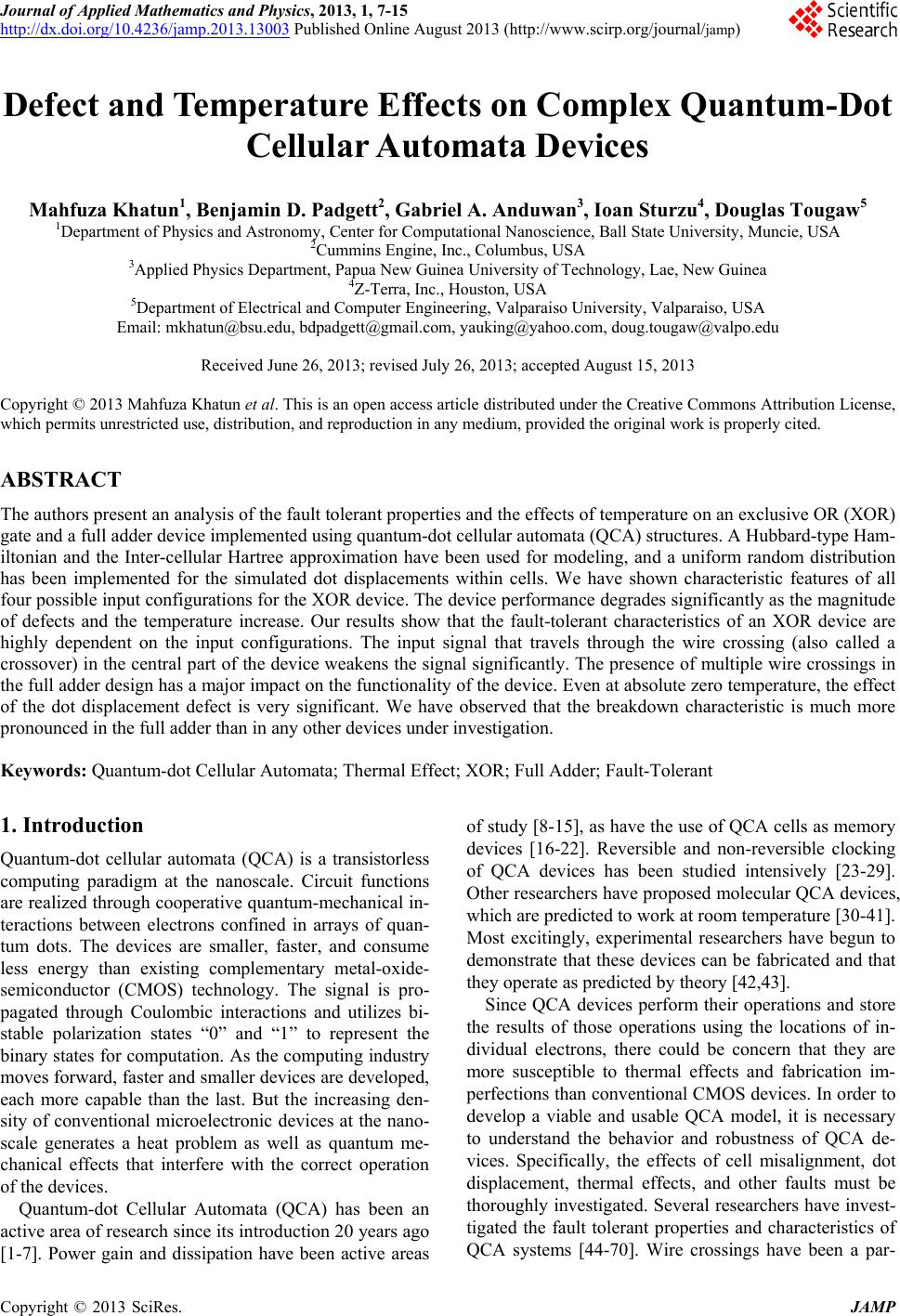
 Journal of Applied Mathematics and Physics, 2013, 1, 7-15 http://dx.doi.org/10.4236/jamp.2013.13003 Published Online August 2013 (http://www.scirp.org/journal/jamp) Defect and Temperature Effects on Complex Quantum-Dot Cellular Automata Devices Mahfuza Khatun1, Benjamin D. Padgett2, Gabriel A. Anduwan3, Ioan Sturzu4, Douglas Tougaw5 1Department of Physics and Astronomy, Center for Computational Nanoscience, Ball State University, Muncie, USA 2Cummins Engine, Inc., Columbus, USA 3Applied Physics Department, Papua New Guinea University of Technology, Lae, New Guinea 4Z-Terra, Inc., Houston, USA 5Department of Electrical and Computer Engineering, Valparaiso University, Valparaiso, USA Email: mkhatun@bsu.edu, bdpadgett@gmail.com, yauking@yahoo.com, doug.tougaw@valpo.edu Received June 26, 2013; revised July 26, 2013; accepted August 15, 2013 Copyright © 2013 Mahfuza Khatun et al. This is an open access article distributed under the Creative Commons Attribution License, which permits unrestricted use, distribution, and reproduction in any medium, provided the original work is properly cited. ABSTRACT The authors present an analysis of the fault tolerant properties and the effects of temperature on an exclusive OR (XOR) gate and a full adder device implemented using quantum-dot cellular automata (QCA) structures. A Hubbard-type Ham- iltonian and the Inter-cellular Hartree approximation have been used for modeling, and a uniform random distribution has been implemented for the simulated dot displacements within cells. We have shown characteristic features of all four possible input configurations for the XOR device. The device performance degrades significantly as the magnitude of defects and the temperature increase. Our results show that the fault-tolerant characteristics of an XOR device are highly dependent on the input configurations. The input signal that travels through the wire crossing (also called a crossover) in the central part of the device weakens the signal significantly. The presence of multiple wire crossings in the full adder design has a major impact on the functionality of the device. Even at absolute zero temperature, the effect of the dot displacement defect is very significant. We have observed that the breakdown characteristic is much more pronounced in the full adder than in any other devices under investigation. Keywords: Quantum-dot Cellular Automata; Thermal Effect; XOR; Full Adder; Fault-Tolerant 1. Introduction Quantum-dot cellular automata (QCA) is a transistorless computing paradigm at the nanoscale. Circuit functions are realized through cooperative quantum-mechanical in- teractions between electrons confined in arrays of quan- tum dots. The devices are smaller, faster, and consume less energy than existing complementary metal-oxide- semiconductor (CMOS) technology. The signal is pro- pagated through Coulombic interactions and utilizes bi- stable polarization states “0” and “1” to represent the binary states for computation. As the computing industry moves forward, faster and smaller devices are developed, each more capable than the last. But the increasing den- sity of conventional microelectronic devices at the nano- scale generates a heat problem as well as quantum me- chanical effects that interfere with the correct operation of the devices. Quantum-dot Cellular Automata (QCA) has been an active area of research since its introduction 20 years ago [1-7]. Power gain and dissipation have been active areas of study [8-15], as have the use of QCA cells as memory devices [16-22]. Reversible and non-reversible clocking of QCA devices has been studied intensively [23-29]. Other researchers have proposed molecular QCA devices, which are predicted to work at room temperature [30-41]. Most excitingly, experimental researchers have begun to demonstrate that these devices can be fabricated and that they operate as predicted by theory [42,43]. Since QCA devices perform their operations and store the results of those operations using the locations of in- dividual electrons, there could be concern that they are more susceptible to thermal effects and fabrication im- perfections than conventional CMOS devices. In order to develop a viable and usable QCA model, it is necessary to understand the behavior and robustness of QCA de- vices. Specifically, the effects of cell misalignment, dot displacement, thermal effects, and other faults must be thoroughly investigated. Several researchers have invest- tigated the fault tolerant properties and characteristics of QCA systems [44-70]. Wire crossings have been a par- C opyright © 2013 SciRes. JAMP 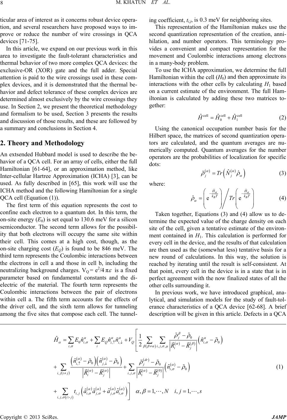 M. KHATUN ET AL. 8 ticular area of interest as it concerns robust device opera- tion, and several researchers have proposed ways to im- prove or reduce the number of wire crossings in QCA devices [71-75]. In this article, we expand on our previous work in this area to investigate the fault-tolerant characteristics and thermal behavior of two more complex QCA devices: the exclusive-OR (XOR) gate and the full adder. Special attention is paid to the wire crossings used in these com- plex devices, and it is demonstrated that the thermal be- havior and defect tolerance of these complex devices are determined almost exclusively by the wire crossings they use. In Section 2, we present the theoretical methodology and formalism to be used, Section 3 presents the results and discussion of those results, and these are followed by a summary and conclusions in Section 4. 2. Theory and Methodology An extsended Hubbard model is used to describe the be- havior of a QCA cell. For an array of cells, either the full Hamiltonian [61-64], or an approximation method, like Inter-cellular Hartree Approximation (ICHA) [3], can be used. As fully described in [65], this work will use the ICHA method and the following Hamiltonian for a single QCA cell (Equation (1)). The first term of this equation represents the cost to confine each electron to a quantum dot. In this term, the on-site energy (E0) is set equal to 130.6 meV for a silicon semiconductor. The second term allows for the possibil- ity that both electrons will occupy the same site within their cell. This comes at a high cost, though, as the on-site charging cost (EQ) is found to be 846 meV. The third term represents the Coulombic interactions between the electrons in cell a and those in cell b, including the neutralizing background charges. VQ = e2/4 π is a fixed parameter based on fundamental constants and the di- electric of the material. The fourth term represents the Coulombic interactions between the pair of electrons within cell a. The fifth term accounts for the effects of the driver cell, and the sixth term allows for tunneling among the five sites that compose each cell. The tunnel- ing coefficient, ti,j, is 0.3 meV for neighboring sites. This representation of the Hamiltonian makes use the second quantization representation of the creation, anni- hilation, and number operators. This terminology pro- vides a convenient and compact representation for the movement and Coulombic interactions among electrons in a many-body problem. To use the ICHA approximation, we determine the full Hamiltonian within the cell (H0) and then approximate its interactions with the other cells by calculating H1 based on a current estimate of the environment. The full Ham- iltonian is calculated by adding these two matrices to- gether: cellcell cell 01 ˆˆˆ HH (2) Using the canonical occupation number basis for the Hilbert space, the matrices of second quantization opera- tors are calculated, and the quantum averages are nu- merically computed. Quantum averages for the number operators are the probabilities of localization for specific dots: ˆˆ jj Tr N (3) where: ˆˆ ˆee B HH kT kT Tr B (4) Taken together, Equations (3) and (4) allow us to de- termine the expected value of the charge density on each site of the cell, given a tentative estimate of the environ- ment contained in H1. This calculation is performed for every cell in the device, and the results of that calculation are then used as the (somewhat less) tentative basis for a new round of calculations. In this way, the solution is reached by iterating until the result is self-consistent. At that point, every cell in the device is in a state that is in perfect agreement with the now finalized states of all the other cells surrounding it. In previous work, we have introduced graphical, ana- lytical, and simulation models for the study of fault-tol- erance characteristics of a QCA device [62-68]. A brief description will be given in this article. Defects in a QCA 0 0, ,0 ,, ,,,, 00 ,, 0 ,0 0 ,,, ,,, ,, ,, 1 ˆˆˆˆ ˆ 2 ˆˆ ˆ ˆˆˆˆ , j iQ Qi ii ii ij ij dr ij ji ijijij ij ij ij ijji iji j HEnEnnV n RR nn n RR RR taa aa 1, ,,1, ,Nij s (1) Copyright © 2013 SciRes. JAMP 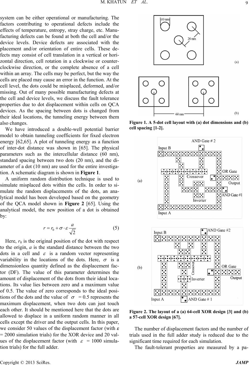 M. KHATUN ET AL. 9 system can be either operational or manufacturing. The factors contributing to operational defects include the effects of temperature, entropy, stray charge, etc. Manu- facturing defects can be found at both the cell and/or the device levels. Device defects are associated with the placement and/or orientation of entire cells. These de- fects may consist of cell translation in a vertical or hori- zontal direction, cell rotation in a clockwise or counter- clockwise direction, or the complete absence of a cell within an array. The cells may be perfect, but the way the cells are placed may cause an error in the function. At the cell level, the dots could be misplaced, deformed, and/or missing. Out of many possible manufacturing defects at the cell and device levels, we discuss the fault tolerance properties due to dot displacement within cells on QCA devices. As the spacing between dots is changed from their ideal locations, the tunneling energy between them also changes. We have introduced a double-well potential barrier model to obtain tunneling coefficients for fixed electron energy [62,65]. A plot of tunneling energy as a function of inter-dot distance was shown in [65]. The physical parameters such as the intercellular distance (60 nm), standard spacing between two dots (20 nm), and the di- ameter of a dot (10 nm) are used for the entire investiga- tion. A schematic diagram is shown in Figure 1. A uniform random distribution technique is used to simulate misplaced dots within the cells. In order to si- mulate the random displacements of the dots, an ana- lytical model has been developed based on the geometry of the QCA model shown in Figure 2 [65]. Using the analytical model, the new position of a dot is obtained by: 02 a rr (5) Here, r0 is the original position of the dot with respect to the origin, a is the standard distance between the two dots in a cell and is a random vector representing variability in the locations of the dots. Here, is a dimensionless quantity defined as the displacement fac- tor (DF). The value of this parameter determines the amount of displacement of the dots from their ideal loca- tions. Its value lies between zero and a maximum value of 0.5. The value of zero corresponds to the ideal posi- tions of the dots and the value of = 0.5 represents the maximum displacement, when two dots can just touch each other. It should be mentioned here that the dots are allowed to displace in a uniform random manner in all cells except the driver and the output cells. In this paper, we consider 50 values of the displacement factor (with ε = 2000 simulation trials) for the XOR device and 20 val- ues of the displacement factor (with = 1000 simula- tion trials) for the full adder. Figure 1. A 5-dot cell layout with (a) dot dimensions and (b) cell spacing [1-2]. Figure 2. The layout of a (a) 64-cell XOR design [3] and (b) a 57-cell XOR design [67]. The number of displacement factors and the number of trials used in the full adder study is reduced due to the significant time required for each simulation. The fault-tolerant properties are measured by a pa- Copyright © 2013 SciRes. JAMP 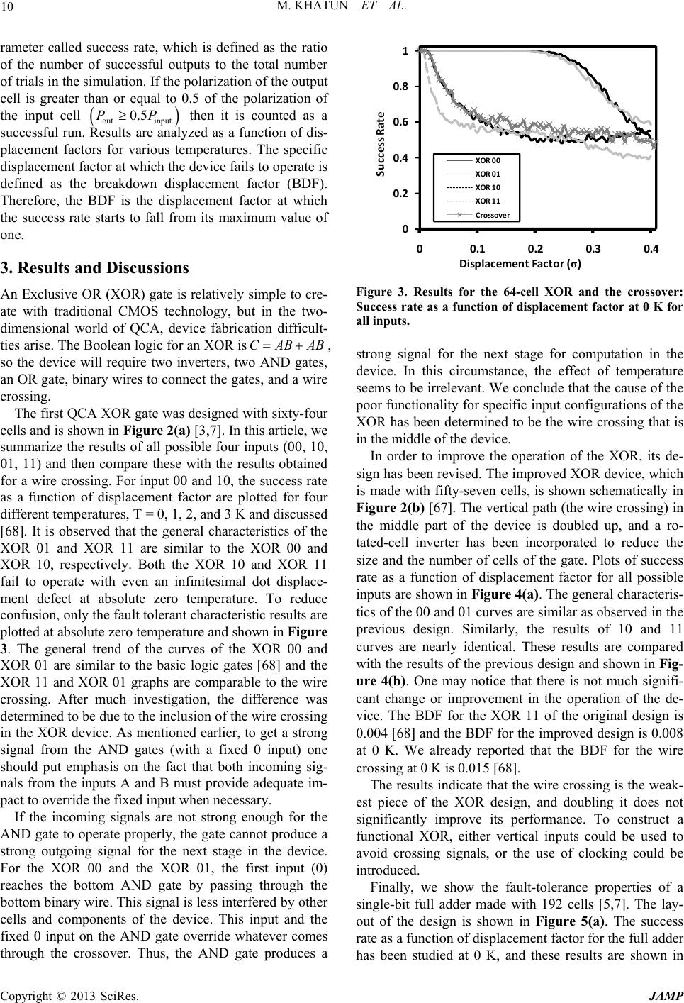 M. KHATUN ET AL. 10 rameter called success rate, which is defined as the ratio of the number of successful outputs to the total number of trials in the simulation. If the polarization of the output cell is greater than or equal to 0.5 of the polarization of the input cell outinput then it is counted as a successful run. Results are analyzed as a function of dis- placement factors for various temperatures. The specific displacement factor at which the device fails to operate is defined as the breakdown displacement factor (BDF). Therefore, the BDF is the displacement factor at which the success rate starts to fall from its maximum value of one. 0.5PP 3. Results and Discussions An Exclusive OR (XOR) gate is relatively simple to cre- ate with traditional CMOS technology, but in the two- dimensional world of QCA, device fabrication difficult- ties arise. The Boolean logic for an XOR isCABAB, so the device will require two inverters, two AND gates, an OR gate, binary wires to connect the gates, and a wire crossing. The first QCA XOR gate was designed with sixty-four cells and is shown in Figure 2(a) [3,7]. In this article, we summarize the results of all possible four inputs (00, 10, 01, 11) and then compare these with the results obtained for a wire crossing. For input 00 and 10, the success rate as a function of displacement factor are plotted for four different temperatures, T = 0, 1, 2, and 3 K and discussed [68]. It is observed that the general characteristics of the XOR 01 and XOR 11 are similar to the XOR 00 and XOR 10, respectively. Both the XOR 10 and XOR 11 fail to operate with even an infinitesimal dot displace- ment defect at absolute zero temperature. To reduce confusion, only the fault tolerant characteristic results are plotted at absolute zero temperature and shown in Figure 3. The general trend of the curves of the XOR 00 and XOR 01 are similar to the basic logic gates [68] and the XOR 11 and XOR 01 graphs are comparable to the wire crossing. After much investigation, the difference was determined to be due to the inclusion of the wire crossing in the XOR device. As mentioned earlier, to get a strong signal from the AND gates (with a fixed 0 input) one should put emphasis on the fact that both incoming sig- nals from the inputs A and B must provide adequate im- pact to override the fixed input when necessary. If the incoming signals are not strong enough for the AND gate to operate properly, the gate cannot produce a strong outgoing signal for the next stage in the device. For the XOR 00 and the XOR 01, the first input (0) reaches the bottom AND gate by passing through the bottom binary wire. This signal is less interfered by other cells and components of the device. This input and the fixed 0 input on the AND gate override whatever comes through the crossover. Thus, the AND gate produces a 0 0.2 0.4 0.6 0.8 1 00.10.20.3 Success Rate Displacement Factor (σ) 0.4 XOR 00 XOR 01 XOR 10 XOR 11 Crossover Figure 3. Results for the 64-cell XOR and the crossover: Success rate as a function of displacement factor at 0 K for all inputs. strong signal for the next stage for computation in the device. In this circumstance, the effect of temperature seems to be irrelevant. We conclude that the cause of the poor functionality for specific input configurations of the XOR has been determined to be the wire crossing that is in the middle of the device. In order to improve the operation of the XOR, its de- sign has been revised. The improved XOR device, which is made with fifty-seven cells, is shown schematically in Figure 2(b) [67]. The vertical path (the wire crossing) in the middle part of the device is doubled up, and a ro- tated-cell inverter has been incorporated to reduce the size and the number of cells of the gate. Plots of success rate as a function of displacement factor for all possible inputs are shown in Figure 4(a). The general characteris- tics of the 00 and 01 curves are similar as observed in the previous design. Similarly, the results of 10 and 11 curves are nearly identical. These results are compared with the results of the previous design and shown in Fig- ure 4(b). One may notice that there is not much signifi- cant change or improvement in the operation of the de- vice. The BDF for the XOR 11 of the original design is 0.004 [68] and the BDF for the improved design is 0.008 at 0 K. We already reported that the BDF for the wire crossing at 0 K is 0.015 [68]. The results indicate that the wire crossing is the weak- est piece of the XOR design, and doubling it does not significantly improve its performance. To construct a functional XOR, either vertical inputs could be used to avoid crossing signals, or the use of clocking could be introduced. Finally, we show the fault-tolerance properties of a single-bit full adder made with 192 cells [5,7]. The lay- out of the design is shown in Figure 5(a). The success rate as a function of displacement factor for the full adder has been studied at 0 K, and these results are shown in Copyright © 2013 SciRes. JAMP 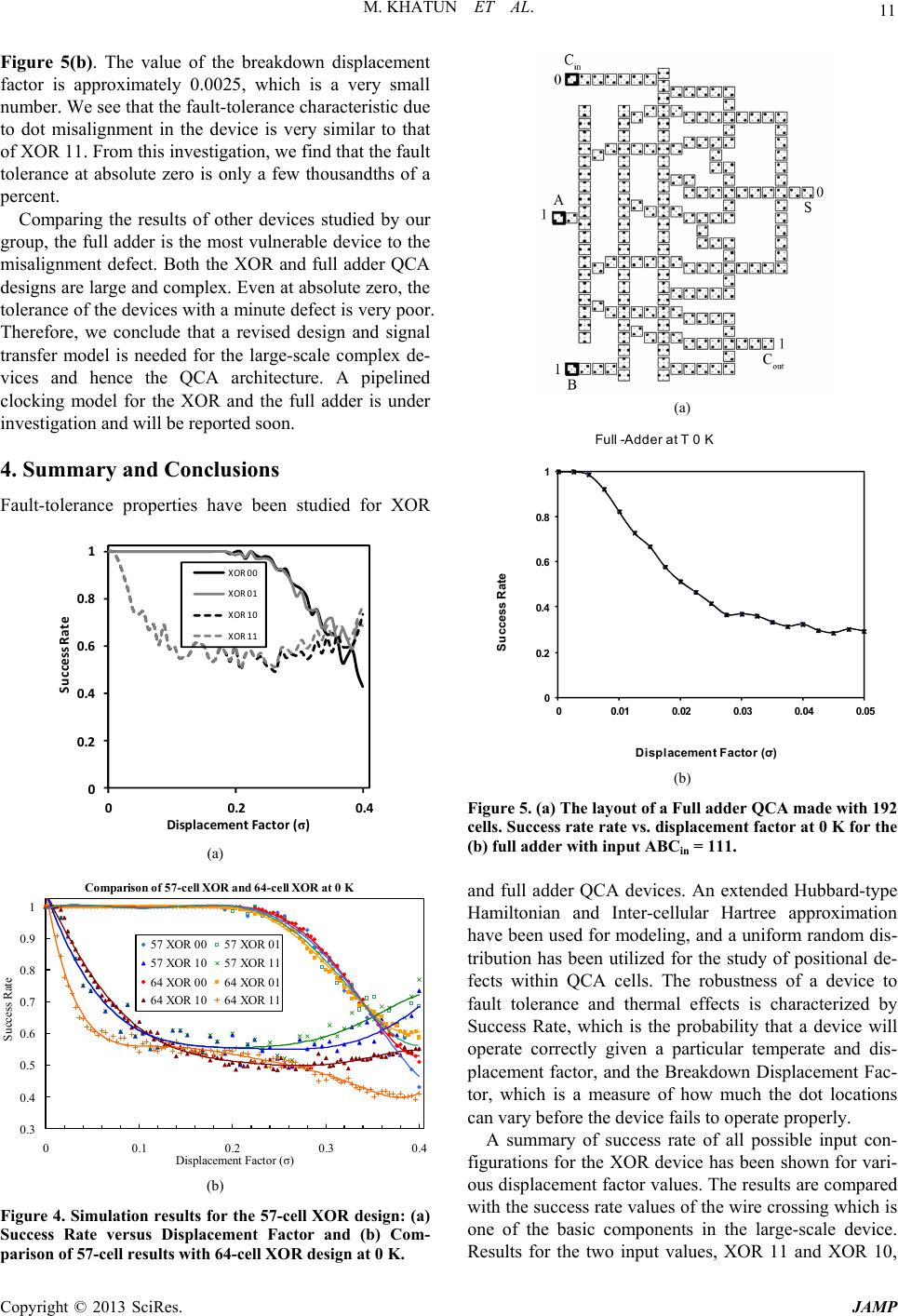 M. KHATUN ET AL. 11 Figure 5(b). The value of the breakdown displacement factor is approximately 0.0025, which is a very small number. We see that the fault-tolerance characteristic due to dot misalignment in the device is very similar to that of XOR 11. From this investigation, we find that the fault tolerance at absolute zero is only a few thousandths of a percent. Comparing the results of other devices studied by our group, the full adder is the most vulnerable device to the misalignment defect. Both the XOR and full adder QCA designs are large and complex. Even at absolute zero, the tolerance of the devices with a minute defect is very poor. Therefore, we conclude that a revised design and signal transfer model is needed for the large-scale complex de- vices and hence the QCA architecture. A pipelined clocking model for the XOR and the full adder is under investigation and will be reported soon. 4. Summary and Conclusions Fault-tolerance properties have been studied for XOR 0 0.2 0.4 0.6 0.8 1 00.2 Success Rate Displacement Factor (σ) 0.4 XOR 00 XOR 01 XOR 10 XOR 11 (a) Comparison of 57-cell XOR and 64-cell XOR at 0 K 0.3 0.4 0.5 0.6 0.7 0.8 0.9 1 00.1 0.20.3 0.4 Displacement Factor (σ) Success Rate 57 XOR 0057 XOR 01 57 XOR 1057 XOR 11 64 XOR 0064 XOR 01 64 XOR 1064 XOR 11 (b) Figure 4. Simulation results for the 57-cell XOR design: (a) Success Rate versus Displacement Factor and (b) Com- parison of 57-cell results with 64-cell XOR design at 0 K. (a) 0 0.2 0.4 0.6 0.8 1 00.01 0.02 0.03 0.04 0.05 Success Rate Displacement Factor (σ) Full -Adder at T 0 K (b) Figure 5. (a) The layout of a Full adder QCA made with 192 cells. Success rate rate vs. displacement factor at 0 K for the (b) full adder with input ABCin = 111. and full adder QCA devices. An extended Hubbard-type Hamiltonian and Inter-cellular Hartree approximation have been used for modeling, and a uniform random dis- tribution has been utilized for the study of positional de- fects within QCA cells. The robustness of a device to fault tolerance and thermal effects is characterized by Success Rate, which is the probability that a device will operate correctly given a particular temperate and dis- placement factor, and the Breakdown Displacement Fac- tor, which is a measure of how much the dot locations can vary before the device fails to operate properly. A summary of success rate of all possible input con- figurations for the XOR device has been shown for vari- ous displacement factor values. The results are compared with the success rate values of the wire crossing which is one of the basic components in the large-scale device. Results for the two input values, XOR 11 and XOR 10, Copyright © 2013 SciRes. JAMP 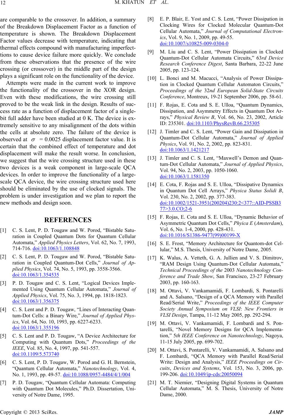 M. KHATUN ET AL. 12 are comparable to the crossover. In addition, a summary of the Breakdown Displacement Factor as a function of temperature is shown. The Breakdown Displacement Factor values decrease with temperature, indicating that thermal effects compound with manufacturing imperfect- tions to cause device failure more quickly. We conclude from these observations that the presence of the wire crossing (or crossover) in the middle part of the design plays a significant role on the functionality of the device. Attempts were made in the current work to improve the functionality of the crossover in the XOR design. Even with these modifications, the wire crossing still proved to be the weak link in the design. Results of suc- cess rate as a function of displacement factor of a single- bit full adder have been studied at 0 K. The device is ex- tremely sensitive to any misalignment of the dots within the cells at absolute zero. The failure of the device is observed at = 0.0025 displacement factor value. It is certain that the combined effect of temperature and dot displacement will make the result worse. In conclusion, we suggest that the wire crossing structure used in these two devices is a weak component in large-scale QCA devices. In order to improve the functionality of a large- scale QCA device, the wire crossing structure used here should be eliminated by the use of clocked signals. The problem is under investigation and we plan to report the new methods and design soon. REFERENCES [1] C. S. Lent, P. D. Tougaw and W. Porod, “Bistable Satu- ration in Coupled Quantum Dots for Quantum Cellular Automata,” Applied Physics Letters, Vol. 62, No. 7, 1993, 714-716. doi:10.1063/1.108848 [2] C. S. Lent, P. D. Tougaw and W. Porod, “Bistable Satu- ration in Coupled Quantum-Dot Cells,” Journal of Ap- plied Physics, Vol. 74, No. 5, 1993, pp. 3558-3566. doi:10.1063/1.354535 [3] P. D. Tougaw and C. S. Lent, “Logical Devices Imple- mented Using Quantum Cellular Automata,” Journal of Applied Physics, Vol. 75, No. 3, 1994, pp. 1818-1823. doi:10.1063/1.356375 [4] C. S. Lent and P. D. Tougaw, “Lines of Interacting Quan- tum-Dot Cells: a Binary Wire,” Journal of Applied Phys- ics, Vol. 64, No. 10, 1993, pp. 6227-6233. doi:10.1063/1.355196 [5] C. S. Lent and P. D. Tougaw, “A Device Architecture for Computing with Quantum Dots,” Proceedings of the IEEE, Vol. 85, No. 4, 1997, pp. 541-557. doi:10.1109/5.573740 [6] C. S. Lent, P. D. Tougaw, W. Porod and G. H. Bernstein, “Quantum Cellular Automata,” Nanotechnology, Vol. 4, No. 1, 1993, pp. 49-57. doi:10.1088/0957-4484/4/1/004 [7] P. D. Tougaw, “Quantum Cellular Automata: Computing with Quantum Dot Molecules,” Ph.D. Dissertation, Uni- versity of Notre Dame, 1995. [8] E. P. Blair, E. Yost and C. S. Lent, “Power Dissipation in Clocking Wires for Clocked Molecular Quantum-Dot Cellular Automata,” Journal of Computational Electron- ics, Vol. 9, No. 1, 2009, pp. 49-55. doi:10.1007/s10825-009-0304-0 [9] M. Liu and C. S. Lent, “Power Dissipation in Clocked Quantum-Dot Cellular Automata Circuits,” 63rd Device Research Conference Digest, Santa Barbara, 22-22 June 2005, pp. 123-124. [10] L. Bonci and M. Macucci, “Analysis of Power Dissipa- tion in Clocked Quantum Cellular Automaton Circuits,” Proceedings of the 32nd European Solid-State Circuits Conference, Montreux, 19-21 September 2006, pp. 58-61. [11] F. Rojas, E. Cota and S. E. Ulloa, “Quantum Dynamics, Dissipation, and Asymmetry Effects in Quantum Dot Ar- rays,” Physical Review B, Vol. 66, No. 23, 2002, Article ID: 235301. doi:10.1103/PhysRevB.66.235305 [12] J. Timler and C. S. Lent, “Power Gain and Dissipation in Quantum-Dot Cellular Automata,” Journal of Applied Physics, Vol. 91, No. 2, 2002, pp. 823-831. doi:10.1063/1.1421217 [13] J. Timler and C. S. Lent, “Maxwell’s Demon and Quan- tum-Dot Cellular Automata,” Journal of Applied Physics, Vol. 94, No. 2, 2003, pp. 1050-1060. doi:10.1063/1.1581350 [14] E. Cota, F. Rojas and S. E. Ulloa, “Dissipative Dynamics in Quantum Dot Cell Arrays,” Physica Status Solidi B, Vol. 230, No. 2, 2002, pp. 377-383. doi:10.1002/1521-3951(200204)230:2<377::AID-PSSB3 77>3.0.CO;2-6 [15] F. Rojas, E. Cota and S. E. Ulloa, “Dynamic Behavior of Asymmetric Quantum Dot Cells,” Phyica E (Amsterdam), Vol. 6, No. 1-4, 2000, pp. 428-431. doi:10.1016/S1386-9477(99)00199-X [16] S. E. Frost, “Memory Architecture for Quantom-dot Cel- lular,” M.S. Thesis, University of Notre Dame, 2005. [17] K. Walus, A. Vetteth, G. A. Jullien and V. S. Dimitrov, “RAM Design Using Quantum-Dot Cellular Automata,” Technical Proceedings of the 2003 Nanotechnology Con- ference and Trade Show, San Francisco, 23-27 February 2003, pp. 160-163. [18] M. Ottavi, V. Vankamamidi, F. Lombardi, S. Pontarelli and A. Salsano, “Design of a QCA Memory with Parallel Read/Serial Write,” Proceedings of the IEEE Computer Society Annual Symposium on VLSI: New Frontiers in VLSI Design, Tampa, 11-12 May 2005, pp. 292-294. [19] M. Ottavi, V. Vankamamidi, F. Lombardi and S. Pon- tarelli, “Novel Memory Designs for QCA Implementa- tion,” 5th IEEE Conference on Nanotechnology, Nagoya, 11-15 July 2005, pp. 699-702. [20] M. Ottavi, S. Pontarelli, V. Vankamamidi, A. Salsano and F. Lombardi, “QCA Memory with Parallel Read/Serial Write: Design and Analysis,” IEEE Proceedings on Cir- cuits, Devices and Systems, Vol. 153, No. 3, 2006, pp. 199-206. doi:10.1049/ip-cds:20050094 [21] M. T. Niemier, “Designing Digital Systems in Quantum Cellular Automata,” M. S. Thesis, University of Notre Dame, 2000. Copyright © 2013 SciRes. JAMP  M. KHATUN ET AL. 13 [22] M. T. Niemier and P. M. Kogge, “Problems in Designing with QCAs: Layout = Timing,” International Journal of Circuit Theory and Applications, Vol. 29, No. 1, 2001, pp. 49-62. doi:10.1002/1097-007X(200101/02)29:1<49::AID-CTA1 32>3.0.CO;2-1 [23] L. Bonci, M. Gattobigio, G. Iannaccone and M. Macucci, “Simulation of Time Evolution of Clocked and Non- clocked Quantum Cellular Automaton Circuits,” Journal of Applied Physics, Vol. 92, No. 6, 2002, pp. 3169-3178. doi:10.1063/1.1501747 [24] V. Vankamamidi, M. Ottavi and F. Lombardi, “Clocking and Cell Placement for QCA,” Proceedings of 6th IEEE Conference on Nanotechnology, Cincinnati, 17-20 June 2006, pp. 343-346. [25] S. E. Frost, T. J. Dysart, P. M. Kogge and C. S. Lent, “Carbon Nanotubes for Quantum-Dot Cellular Automata Clocking,” 4th IEEE Conference on Nanotechnology, Munich, 16-19 August 2004, pp. 171-173. [26] C. S. Lent, M. Liu and Y. Lu, “Bennett Clocking of Quantum-Dot Cellular Automata and the Limits to Binary Logic Scaling,” Nanotechnology, Vol. 17, No. 16, 2006, pp. 4240-4251. doi:10.1088/0957-4484/17/16/040 [27] K. Hennessy and C. Lent, “Clocking of Molecular Quan- tum-dot Cellular Automata,” Journal of Vacuum Science & Technology, Vol. 19, No. 5, 2001, pp. 1752-1755. [28] C. S. Lent and B. Isaksen, “Clocked Molecular Quan- tum-Dot Cellular Automata,” IEEE Transactions on Elec- tron Devices, Vol. 50, No. 9, 2003, pp. 1890-1896. doi:10.1109/TED.2003.815857 [29] V. Vankamamidi, M. Ottavi and F. Lombardi, “Two- Dimensional Schemes for Clocking/Timing of QCA Cir- cuits,” IEEE Transactions on Computer-Aided Design of Integrated Circuits and Systems, Vol. 27, No. 1, 2008, pp. 34-44. doi:10.1109/TCAD.2007.907020 [30] Y. Lu, M. Liu, and C. S. Lent, “Molecular Quantum-Dot Cellular Automata: From Molecular Structure to Circuit Dynamics,” Journal of Applied Physics, Vol. 102, No. 3, 2007, Article ID: 034311. doi:10.1063/1.2767382 [31] Z. Jin, “Fabrication and Measurement of Molecular Quan- tum Cellular Automata,” Ph.D. Dissertation, University of Notre Dame, 2006. [32] J. Jiao, “Synthesis, Characterization and Surface Attach- ment of Square Mixed-valence Complexes as Building Blocks for Molecular Quantum Cellular Automata,” Ph.D. Dissertation, University of Notre Dame, 2004. [33] Q. Hang, “Molecular Liftoff Technology by Electron Beam Lithography for Molecular Electronic Devices,” Ph.D. Dissertation, University of Notre Dame, 2004. [34] C. S. Lent and B. Isaken, “Clocked Molecular Quan- tum-Dot Cellular Automata,” IEEE Transactions on Elec- tron Devices, Vol. 50, No. 9, 2003, pp. 1890-1896. doi:10.1109/TED.2003.815857 [35] H. Qi, S. Sharma, Z. Li, G. L. Snider, A. O. Orlov, C. S. Lent and T. P. Fehlner, “Molecular Quantum Cellular Automata Cells Electric Field Driven Switching of a Silicon Surface Bound Array of Vertically Oriented Two-Dot Molecular Quantum Cellular Automata,” Jour- nal of the American Chemical Society, Vol. 125, No. 49, 2003, pp. 15250-15259. doi:10.1021/ja0371909 [36] Z. Li and T. P. Fehlner, “Molecular QCA Cells. 2. Cha- racterization of an Unsymmetrical Dinuclear Mixed-Va- lence Complex Bound to a Au Surface by an Organic Linker,” Inorganic Chemistry, Vol. 42, No. 18, 2003, pp. 5715-5721. doi:10.1021/ic026255q [37] Q. L. Hang, Y. L. Wang, M. Lieberman and G. H. Bernstein, “Molecular Patterning through High-Resolu- tion Polymethylmethacrylate Masks,” Applied Physics Letters, Vol. 80, No. 22, 2002, pp. 4220-4222. doi:10.1063/1.1481784 [38] J. Jiao, G. J. Long, F. Grandjean, A. M. Beatty and T. P. Fehlner, “Building Blocks for the Molecular Expression of Quantum Cellular Automata. Isolation and Characteri- zation of a Covalently Bonded Square Array of Two Ferrocenium and Two Ferrocene Complexes,” Journal of the American Chemical Society, Vol. 125, No. 25, 2003, pp. 7522-7523. doi:10.1021/ja035077c [39] C. S. Lent, B. Isaksen and M. Lieberman, “Molecular Quantum-Dot Cellular Automata,” Journal of the Ameri- can Chemical Society, Vol. 125, No. 4, 2003, pp. 1056- 1063. doi:10.1021/ja026856g [40] Y. Lu and C. S. Lent, “A Metric for Characterizing the Bistability of Quantum-Dot Cellular Automata,” Nano- technology, Vol. 19, No. 15, 2008, p. 155703. doi:10.1088/0957-4484/19/15/155703 [41] K. Hennessy and C. S. Lent, “Clocking of Molecular Quantum-Dot Cellular Automata,” Journal of Vacuum Science & Technology B, Vol. 19, No. 5, 2001, pp. 1752- 1755. doi:10.1116/1.1394729 [42] K. K. Yadavalli, A. O. Orlov, J. P. Timler, C. S. Lent and G. L. Snider, “Fanout Gate in Quantum-Dot Cellular Automata,” Nanotechnology, Vol. 18, No. 37, 2007, p. 375401. doi:10.1088/0957-4484/18/37/375401 [43] A. O. Orlov, R. Kummamuru, R. Ramasubramaniam, C. S. Lent, G. H. Bernstein and G. L. Snider, “Clocked Quantum-Dot Cellular Automata Shift Register,” Surface Science, Vol. 532, 2003, pp. 1193-1198. [44] J. Huang, M. Momenzadeh and F. Lombardi, “Defect Tolerance of QCA Tiles,” Proceedings of the Conference on Design, Automation and Test in Europe, Munich, 6-10 March 2006, pp. 774-776. doi:10.1109/DATE.2006.244118 [45] S. Bhanja, M. Ottavi, F. Lombardi and S. Pontarelli, “Novel Designs for Thermally Robust Coplanar Crossing in QCA,” Proceedings of the Conference on Design, Automation and Test in Europe, Munich, 6-10 March 2006, pp. 786-791. doi:10.1109/DATE.2006.244120 [46] M. Momenzadeh, M. Ottavi and F. Lombardi, “Modeling QCA Defects at Molecular-Level in Combinational Cir- cuits,” IEEE International Symposium on Defect and Fault Tolerance in VLSI Systems, Monterey, 3-5 October 2005, pp. 208-216. [47] M. B. Tahoori, J. Huang, M. Momenzadeh and F. Lom- bardi, “Defects and Fault Characterization in Quantum Cellular Automata,” Proceedings of the Nanotechnology Conference and Trade Show, Vol. 3, 2004, pp. 190-193. Copyright © 2013 SciRes. JAMP  M. KHATUN ET AL. 14 [48] M. Liu and C. S. Lent, “Reliability and Defect Tolerance in Metallic Quantum-Dot Cellular Automata,” Journal of Electronic Test ing, Vol. 23, No. 2-3, 2007, pp. 211-218. doi:10.1007/s10836-006-0627-8 [49] T. J. Dysart, “Defect Properties and Design Tools for Quantum Dot Cellular Automata,” M.S. Thesis, Univer- sity of Notre Dame, South Bend, 2005. [50] T. J. Dysart and P. M. Kogge, “Strategy and Prototype Tool for Doing Fault Modeling in a Nano-Technology,” 3rd IEEE Conference on Nanotechnology, San Francisco, 12-14 August 2003, pp. 356-359. [51] J. Han, E. Taylor, J. Gao and J. Fortes, “Faults, Error Bounds and Reliability of Nanoelectronic Circuits,” Pro- ceedings of the 2005 IEEE International Conference on Application-Specific Systems, Architecture Processors, Samos, 23-25 July 2005, pp. 247-253. doi:10.1109/ASAP.2005.36 [52] T. Wei, K. Wu, R. Karri and A. Orailoglu, “Fault Tole- rant Quantum Cellular Array (QCA) Design Using Triple Modular Redundancy with Shifted Operands,” Proceed- ings of the 2005 Asia and South Pacific Design Automa- tion Conference, Shanghai, 18-21 January 2005, pp. 1192-1195. doi:10.1145/1120725.1120938 [53] M. Momenzadeh, J. Huang and F. Lombardi, “Defect Characterization and Tolerance of QCA Sequential De- vices and Circuits,” Proceedings of the 20th IEEE Inter- national Symposium on Defect and Fault Tolerance in VLSI Systems, Austin, 3-5 October 2005, pp. 199-207. [54] M. Momenzadeh, M. B. Tahoori, J. Huang and F. Lom- bardi, “Quantum Cellular Automata: New Defects and Faults for New Devices,” Proceedings of the 18th In- ternational Parallel and Distributed Processing Sympo- sium, Santa Fe, 26-30 April 2004, pp. 207-214. [55] M. B. Tahoori, M. Momenzadeh, J. Huang and F. Lom- bardi, “Defects and Faults in Quantum Cellular Automata at Nano Scale,” Proceedings of the 22nd IEEE VLSI Test Symposium, Napa Valley, 25-29 April 2004, pp. 291-296. [56] A Fijany and B. N. Toomarian, “New Design for Quan- tum Dots Cellular Automata to Obtain Fault Tolerant Logic Gates,” Journal of Nanoparticle Research, Vol. 3, No. 1, 2001, pp. 27-31.doi:10.1023/A:1011415529354 [57] C. G. Smith, “Computation without Current,” Science, Vol. 284, No. 5412, 1999, p. 274. doi:10.1126/science.284.5412.274 [58] M. Governale, M. Macucci, G. Iannaccone, C. Ungarelli, and J. Martorell, “Modeling and Manufacturability As- sessment of Bistable Quantum-Dot Cells,” Journal of Ap- plied Physics, Vol. 85, No. 5, 1999, pp. 2962-2971. doi:10.1063/1.369061 [59] J. L. Kanuchok, “The Thermal Effect and Clocking in Quantum-Dot Cellular Automata,” M.S. Thesis, Ball State University, Muncie, 2003. [60] I. Sturzu, J. L. Kanuchok, M. Khatun and P. D. Tougaw, “Thermal Effect in Quantum-Dot Cellular Automata,” Physica E, Vol. 27, No. 1-2, 2005, pp. 188-197. doi:10.1016/j.physe.2004.11.001 [61] I. Sturzu and M. Khatun, “Quantum Calculation of Ther- mal Effect in Quantum-Dot Cellular Automata,” Com- plexity, Vol. 10, No. 4, 2005, pp. 73-78. doi:10.1002/cplx.20081 [62] M. K. Hendrichsen, “Thermal Effect and Fault Tolerance in Quantum-Dot Cellular Automata,” M.S. Thesis, Ball State University, Muncie, 2005. [63] T. Barclay, “The Temperature Effect and Defect Study in Quantum-Dot Cellular Automata,” M.S. Thesis, Ball State University, Muncie, 2005. [64] M. Khatun, T. Barclay, I. Sturzu and P. D. Tougaw, “Fault Tolerance Calculations for Clocked Quantum-Dot Cellular Automata Devices,” Journal of Applied Physics, Vol. 98, No. 9, 2005, Article ID: 094904. doi:10.1063/1.2128473 [65] M. Khatun, T. Barclay, I. Sturzu and P. D. Tougaw, “Fault Tolerance Properties in Quantum-Dot Cellular Automata Devices,” Journal of Physics D: Applied Phy- sics, Vol. 39, No. 8, 2006, pp. 1489-1494. doi:10.1088/0022-3727/39/8/006 [66] B. Padgett, G. Anduwan, M. Kuntzman, I. Sturzu and M. Khatun, “Modeling and Simulation of Fault Tolerant Quantum-Dot Cellular Automata Devices,” American Physical Society, Vol. 54, 2009, p. 280. [67] B. D. Padgett, “Modeling and Simulation of Fault Toler- ant Properties of Quantum-Dot Cellular Automata De- vices,” M.S. Thesis, Ball State University, Muncie, 2010. [68] G. A. Anduwan, B. D. Padgett, M. Kuntzman, M. K. Hendrichsen, I. Sturzu, M. Khatun and P. D. Tougaw, “Fault-Tolerance and Thermal Characteristics of Quan- tum-Dot Cellular Automata Devices,” Journal of Applied Physics, Vol. 107, No. 11, 2010, p. 114306. doi:10.1063/1.3428453 [69] G. Anduwan, “The Thermal Effect and Fault Tolerance on Nanoscale Devices: The Quantum Dot Cellular Auto- ta,” Doctoral in Education (ED. D) Dissertation, Ball State University, Muncie, 2007. [70] R. K. Kummamuru, A. O. Orlov, R. Ramasubramaniam, C. S. Lent, G. H. Bernstein and G. L. Snider, “Operation of a Quantum-Dot Cellular Automata (QCA) Shift Re- ster and Analysis of Errors,” IEEE Transactions on Elec- tron Devices, Vol. 50, No. 9, 2003, pp. 1906-1913. doi:10.1109/TED.2003.816522 [71] S. Bhanja, M. Ottavi, F. Lombardi and S. Pontarelli, “QCA Circuits for Robust Coplanar Crossing,” Journal of Electronic Test ing, Vol. 23, No. 2-3, 2007, pp. 193-210. doi:10.1007/s10836-006-0551-y [72] W. J. Chung, B. Smith and S. K. Lim, “Node Duplication and Routing Algorithms for Quantum-Dot Cellular Auto- mata Circuits,” IEE Proceedings on Circuits, Devices and Systems, Vol. 153, No. 5, 2006, pp. 497-505. doi:10.1049/ip-cds:20050278 [73] A. Chaudhary, D. Z. Chen, X. S. Hu, K. Whitton, M. Niemier and R. Ravichardran, “Eliminating Wire Cross- ings for Molecular Quantum-Dot Cellular Automata Im- plementation,” Proceedings of IEEE/ACM International Conference on Computer-Aided Design, San Jose, 6-10 November 2005, pp. 565-571. [74] B. S. Smith and S. K. Lim, “QCA Channel Routing with Wire Crossing Minimization,” Proceedings of the 15th Copyright © 2013 SciRes. JAMP  M. KHATUN ET AL. Copyright © 2013 SciRes. JAMP 15 ACM Great Lakes symposium on VLSI, Chicago, 17-19 April 2005, pp. 217-220. [75] W. J. Chung, B. S. Smith and S. K. Lim, “QCA Physical Design with Crossing Minimization,” Proceedings of the 5th IEEE Conference on Nanotechnology, Nagoya, 11-15 July 2005, pp. 262-265.
|