Paper Menu >>
Journal Menu >>
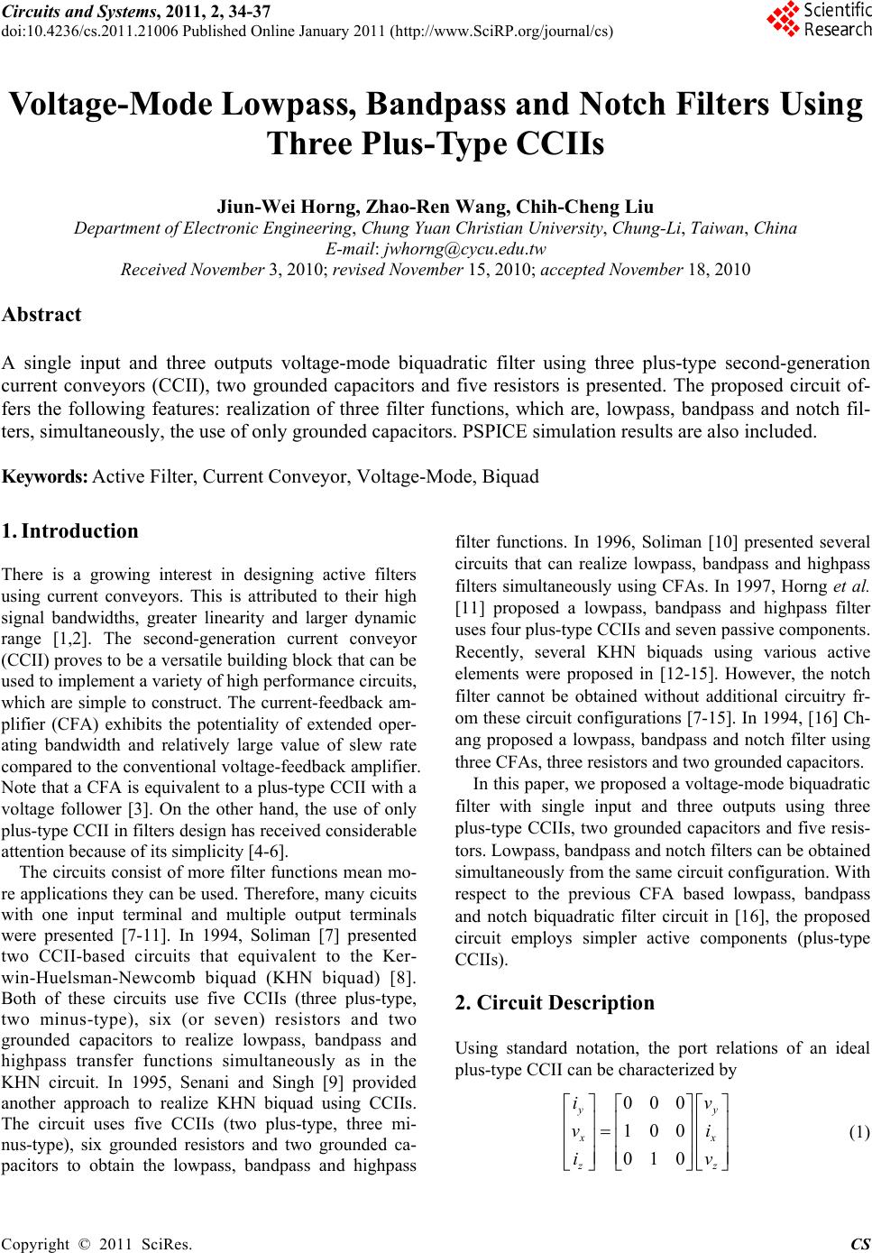 Circuits and Systems, 2011, 2, 34-37 doi:10.4236/cs.2011.21006 Published Online January 2011 (http://www.SciRP.org/journal/cs) Copyright © 2011 SciRes. CS Voltage-Mode Lowpass, Bandpass and Notch Filters Using Three Plus-Type CCIIs Jiun-Wei Horng, Zhao-Ren Wang, Chih-Cheng Liu Department of Electronic Engineering, Chung Yuan Christian University, Chung-Li, Taiwan, China E-mail: jwhorng@cycu.edu.tw Received November 3, 2010; revised November 15, 2010; accepted November 18, 2010 Abstract A single input and three outputs voltage-mode biquadratic filter using three plus-type second-generation current conveyors (CCII), two grounded capacitors and five resistors is presented. The proposed circuit of- fers the following features: realization of three filter functions, which are, lowpass, bandpass and notch fil- ters, simultaneously, the use of only grounded capacitors. PSPICE simulation results are also included. Keywords: Active Filter, Current Conveyor, Voltage-Mode, Biquad 1. Introduction There is a growing interest in designing active filters using current conveyors. This is attributed to their high signal bandwidths, greater linearity and larger dynamic range [1,2]. The second-generation current conveyor (CCII) proves to be a versatile building block that can be used to implement a variety of high performance circuits, which are simple to construct. The current-feedback am- plifier (CFA) exhibits the potentiality of extended oper- ating bandwidth and relatively large value of slew rate compared to the conventional voltage-feedback amplifier. Note that a CFA is equivalent to a plus-type CCII with a voltage follower [3]. On the other hand, the use of only plus-type CCII in filters design has received considerable attention because of its simplicity [4-6]. The circuits consist of more filter functions mean mo- re applications they can be used. Therefore, many cicuits with one input terminal and multiple output terminals were presented [7-11]. In 1994, Soliman [7] presented two CCII-based circuits that equivalent to the Ker- win-Huelsman-Newcomb biquad (KHN biquad) [8]. Both of these circuits use five CCIIs (three plus-type, two minus-type), six (or seven) resistors and two grounded capacitors to realize lowpass, bandpass and highpass transfer functions simultaneously as in the KHN circuit. In 1995, Senani and Singh [9] provided another approach to realize KHN biquad using CCIIs. The circuit uses five CCIIs (two plus-type, three mi- nus-type), six grounded resistors and two grounded ca- pacitors to obtain the lowpass, bandpass and highpass filter functions. In 1996, Soliman [10] presented several circuits that can realize lowpass, bandpass and highpass filters simultaneously using CFAs. In 1997, Horng et al. [11] proposed a lowpass, bandpass and highpass filter uses four plus-type CCIIs and seven passive components. Recently, several KHN biquads using various active elements were proposed in [12-15]. However, the notch filter cannot be obtained without additional circuitry fr- om these circuit configurations [7-15]. In 1994, [16] Ch- ang proposed a lowpass, bandpass and notch filter using three CFAs, three resistors and two grounded capacitors. In this paper, we proposed a voltage-mode biquadratic filter with single input and three outputs using three plus-type CCIIs, two grounded capacitors and five resis- tors. Lowpass, bandpass and notch filters can be obtained simultaneously from the same circuit configuration. With respect to the previous CFA based lowpass, bandpass and notch biquadratic filter circuit in [16], the proposed circuit employs simpler active components (plus-type CCIIs). 2. Circuit Description Using standard notation, the port relations of an ideal plus-type CCII can be characterized by 000 100 010 yy x x z z iv vi iv (1) 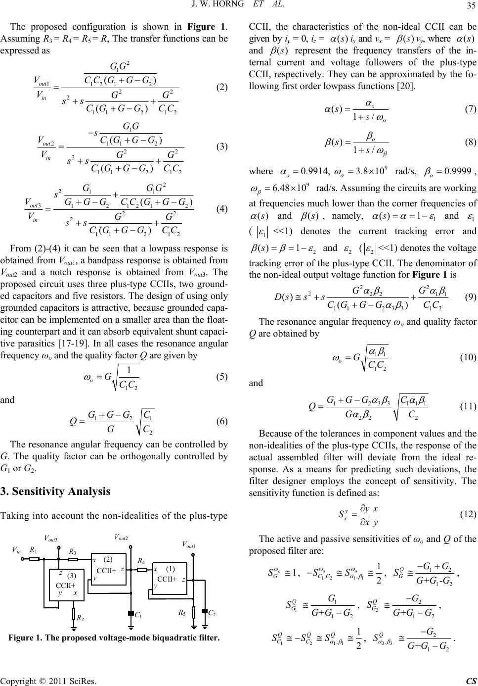 J. W. HORNG ET AL. Copyright © 2011 SciRes. CS 35 The proposed configuration is shown in Figure 1. Assuming R3 = R4 = R5 = R, The transfer functions can be expressed as 2 1 112 12 22 2 112 12 () () out in GG VCC GGG VGG ss CGG GCC (2) 1 211 2 22 2 112 12 () () out in GG s VCGG G VGG ss CGG GCC (3) 2 211 3121212 22 2 112 12 () () out in GGG s VGGG CCGGG VGG ss CGG GCC (4) From (2)-(4) it can be seen that a lowpass response is obtained from Vout1, a bandpass response is obtained from Vout2 and a notch response is obtained from Vout3. The proposed circuit uses three plus-type CCIIs, two ground- ed capacitors and five resistors. The design of using only grounded capacitors is attractive, because grounded capa- citor can be implemented on a smaller area than the float- ing counterpart and it can absorb equivalent shunt capaci- tive parasitics [17-19]. In all cases the resonance angular frequency ωo and the quality factor Q are given by 12 1 oGCC (5) and 121 2 GGG C QGC (6) The resonance angular frequency can be controlled by G. The quality factor can be orthogonally controlled by G1 or G2. 3. Sensitivity Analysis Taking into account the non-idealities of the plus-type V in V out1 z C 1 V out3 CCII+ z x y CCII+ x y R 3 z CCII+ x y C 2 R 1 R 2 R 4 R 5 V out2 (3) (2) (1) Figure 1. The proposed voltage-mode biquadratic filter. CCII, the characteristics of the non-ideal CCII can be given by iy = 0, iz = () s ix and vx = () s vy, where () s and () s represent the frequency transfers of the in- ternal current and voltage followers of the plus-type CCII, respectively. They can be approximated by the fo- llowing first order lowpass functions [20]. () 1/ o ss (7) () 1/ o ss (8) where 0.9914, o 9 3.8 10 rad/s, 0.9999 o , 9 6.48 10 rad/s. Assuming the circuits are working at frequencies much lower than the corner frequencies of () s and () s , namely, 1 () 1s and 1 (1 <<1) denotes the current tracking error and 2 () 1s and 2 (2 <<1) denotes the voltage tracking error of the plus-type CCII. The denominator of the non-ideal output voltage function for Figure 1 is 22 222 11 11233 12 () () GG Dsss CGG GCC (9) The resonance angular frequency ωo and quality factor Q are obtained by 11 12 oGCC (10) and 1233 111 22 2 GGG C QGC (11) Because of the tolerances in component values and the non-idealities of the plus-type CCIIs, the response of the actual assembled filter will deviate from the ideal re- sponse. As a means for predicting such deviations, the filter designer employs the concept of sensitivity. The sensitivity function is defined as: y x yx S x y (12) The active and passive sensitivities of ωo and Q of the proposed filter are: 1 o ω G S , 12 11 , 1 2 oo ω C,C SS , 12 12 +- Q G GG SGGG , 1 1 12 + Q G G SGG G , 2 2 12 + Q G G SGG G , 1211 , 1 2 QQQ CC SSS , 33 2 , 12 + QG SGG G .  J. W. HORNG ET AL. Copyright © 2011 SciRes. CS 36 These values have been calculated by assuming that 1 α, 2 α, 3 α, 1 β , 2 β and 3 β are near unity. 4. Simulation Results The proposed circuit was simulated using PSPICE. The plus-type CCII was implemented using one AD844. The supply voltages are chosen as 12 V. The following set- ting were selected to obtain the lowpass, bandpass and notch filters: R1 = R2 = R3 = R4 = R5 = 1 kΩ, C1 = C2 = 1 nF with Q = 1 and fo = 159.15 KHz. Figures 2 (a), (b) and (c) represent the simulated frequency responses for the lowpass (Vout1), bandpass (Vout2) and notch (Vout3) filters of Figure 1, respectively. The simulation results are co- herent with the theoretical analyses. The CCII has para- sitic resistor from the z terminal to the ground (Rz [21]). When the z terminal load of the CCII is a capacitor (C), it in troduces a pole produced by Rz and C at low frequency. This explains why Figure 2(b) has non-ideal phase res- ponses at low frequencies. This effect can be minimized by using larger loading capacitor or operating the filter in high frequencies. 5. Conclusions In this paper, a new single input and three outputs vol- tage-mode biquadratic filter is presented. The proposed circuit uses three plus-type CCIIs, two grounded capaci- 10 3 10 4 10 5 10 6 10 7 - 80 - 70 - 60 - 50 - 40 - 30 - 20 - 10 0 10 Frequency, Hz Gain, dB Theo. Simu. o o o Gain x x x Phase -.-.-.- Phase, deg 0 - 180 - 90 (a) 10 3 10 4 10 5 10 6 10 7 - 50 - 40 - 30 - 20 - 10 0 10 Frequency, Hz Gain, dB Theo. Simu. o o o Gain x x x Phase -.-.-.- Phase, deg 0 - 180 180 (b) 10 3 10 4 10 5 10 6 10 7 - 25 - 20 - 15 - 10 - 5 0 5 Frequency, Hz Gain, dB Theo. Simu. o o o Gain x x x Phase -.-.-.- Phase, deg 0 - 90 90 (c) Figure 2. Simulated frequency responses of Figure 1 design with C1 = C2 = 1 nF and R1 = R2 = R3 = R4 = R5 = 1 kΩ. (a) lowpass filter (Vout1); (b) bandpass filter (Vout2), (c) notch filter (Vout3). tors and five resistors. The new circuit offers several advantages, such as the realization of lowpass, bandpass, and notch filter functions, simultaneously, in the same circuit configuration; the use of only three plus-type CC -IIs; orthogonally controllable of resonance angular fre- quency and quality factor and the use of only grounded capacitors. 6. References [1] C. Toumazou, F. J. Lidgey and D. G. Haigh, “Analogue IC Design: The Current-mode Approach,” Peter Peregri- nus Ltd., London, 1990. [2] G. W. Roberts and A. S. Sedra, “All Current-Mode Fre- quency Selective Circuits,” Electronics Letters, Vol. 25, No. 12, 1989, pp. 759-761. doi:10.1049/el:19890513 [3] J. A. Svoboda, L. McGory and S. Webb, “Applications of a Commercially Available Current Conveyor,” Interna- tional Journal of Electronics, Vol. 70, No. 1, 1991, pp. 159-164. doi:10.1080/00207219108921266 [4] M. Higashimura and Y. Fukui, “Universal Filter Using Plus-Type CCIIs,” Electronics Letters, Vol. 32, No. 9, 1996, pp. 810-811. doi:10.1049/el:19960518 [5] T. Tsukutani, Y. Sumi and N. Yabuki, “Versatile Cur- rent-Mode Biquadratic Circuit Using Only Plus Type CCCIIs and Grounded Capacitors,” International Journal of Electronics, Vol. 94, No. 12, 2007, pp. 1147-1156. doi:10.1080/00207210701789998 [6] J. W. Horng, “Voltage/Current-Mode Universal Biqua- dratic Filter Using Single CCII+,” Indian Journal of Pure & Applied Physics, Vol. 48, No. 10, 2010, pp. 749-756. [7] A. M. Soliman, “Kerwin-Huelsman-Newcomb Circuit using Current Conveyors,” Electronics Letters, Vol. 30, No. 24, 1994, pp. 2019-2020. doi:10.1049/el:19941368 [8] W. Kerwin, L. Huelsman and R. Newcomb, “State Vari- able Synthesis for Insensitive Integrated Circuit Transfer Functions,” IEEE Journal of Solid State Circuits, Vol. 2, No. 3, 1967, pp. 87-92. doi:10.1109/JSSC.1967.1049798  J. W. HORNG ET AL. Copyright © 2011 SciRes. CS 37 [9] R. Senani and V. K. Singh, “KHN-Equivalent Biquad Using Current Conveyors,” Electronics Letters, Vol. 31, No. 8, 1995, pp. 626-628. doi:10.1049/el:19950422 [10] A. M. Soliman, “Applications of the Current Feedback Amplifiers,” Analog Integrated Circuits and Signal Pro- cessing, Vol. 11, 1996, pp. 265-302. doi:10.1007/BF002 40490 [11] J. W. Horng, J. R. Lay, C. W. Chang and M. H. Lee, “High Input Impedance Voltage-Mode Multifunction Filters Using Plus-Type CCIIs,” Electronics Letters, Vol. 33, No. 6, 1997, pp. 472-473. doi:10.1049/el:19970297 [12] E. Altuntas and A. Toker, “Realization of Voltage and Current Mode KHN Biquads Using CCCIIs,” AEU In- ternational Journal of Electronics and Communications, Vol. 56, No. 1, 2002, pp. 45-49. doi:10.1078/1434-8411- 54100071 [13] A. M. Soliman, “Kerwin Huelsman Newcomb Filter Us- ing Inverting CCII,” Journal of Active and Passive Elec- tronic Devices, Vol. 3, 2008, pp. 273-279. [14] S. Minaei and M. A. Ibrahim, “A Mixed-Mode KHN- Biquad Using DVCC and Grounded Passive Elements Suitable for Direct Cascading,” International Journal of Circuit Theory and Applications, Vol. 37, 2009, pp. 793- 810. doi:10.1002/cta.493 [15] J. Koton, N. Herencsar and K. Vrba, “Single-Input Three- Output Variable Q and ω0 Filters Using Universal Vol- tage Conveyors,” International Journal of Electronics, Vol. 97, No. 5, 2010, pp. 531-538. doi:10.1080/0020721 0903486864 [16] C. M. Chang, C. S. Hwang and S. H. Tu, “Voltage-Mode Notch, Lowpass and Bandpass Filter Using Current-Feed- Back Amplifiers,” Electronics Letters, Vol. 30, No. 24, 1994, pp. 2022-2023. doi:10.1049/el:19941416 [17] M. Bhushan and R. W. Newcomb, “Grounding of Capa- citors in Integrated Circuits,” Electronic Letters, Vol. 3, No. 4, 1967, pp. 148-149. doi:10.1049/el:19670114 [18] E. Yuce and S. Minaei, “ICCII-Based Universal Cur- rent-Mode Analog Filter Employing Only Grounded Pas- sive Components,” Analog Integrated Circuits and Signal Processing, Vol. 58, 2009, pp. 161-169. doi:10.1007/ s10470-008-9225-2 [19] C. M. Chang, A. M. Soliman and M. N. S. Swamy, “Analytical Synthesis of Low-Sensitivities High-Order Voltage-Mode DDCC and FDCCII-Grounded R and C All-Pass Filter Structures,” IEEE Transactions on Cir- cuits and Systems I: Regular Papers, Vol. 54, No. 7, 2007, pp. 1430-1443. doi:10.1109/TCSI.2007.900183 [20] A. Fabre, O. Saaid and H. Barthelemy, “On the Frequen- cy Limitations of the Circuits Based on Second Genera- tion Current Conveyors,” Analog Integrated Circuits and Signal Processing, Vol. 7, 1995, pp. 113-129. doi:10.100 7/BF01239166 [21] J. W. Horng, “High-Order Current-Mode and Transim- pedance-Mode Universal Filters with Multiple-Inputs and Two-Outputs Using MOCCIIs,” Radioengineering, Vol. 18, No. 4, 2009, pp. 537-543. |