Paper Menu >>
Journal Menu >>
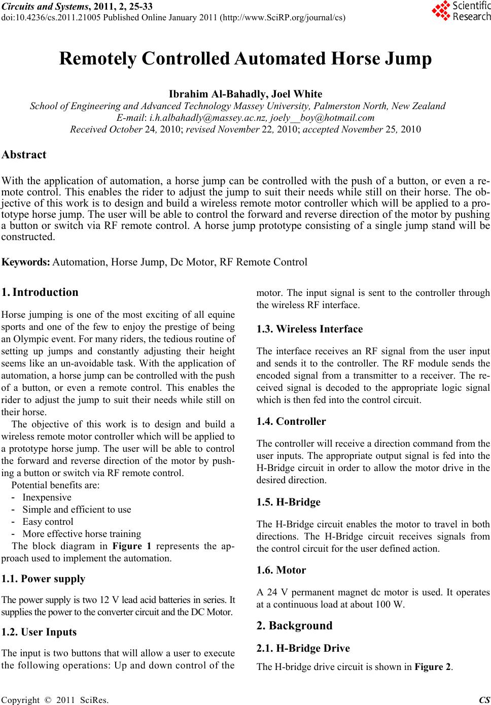 Circuits and Systems, 2011, 2, 25-33 doi:10.4236/cs.2011.21005 Published Online January 2011 (http://www.SciRP.org/journal/cs) Copyright © 2011 SciRes. CS Remotely Controlled Automated Horse Jump Ibrahim Al-Bahadly, Joel White School of Engineering and Advanced Technology Massey University, Palmerston North, New Zealand E-mail: i.h.albahadly@massey.ac.nz, joely__boy@hotmail.com Received October 24, 2010; revised November 22, 2010; accepted N ovember 25, 2010 Abstract With the application of automation, a horse jump can be controlled with the push of a button, or even a re- mote control. This enables the rider to adjust the jump to suit their needs while still on their horse. The ob- jective of this work is to design and build a wireless remote motor controller which will be applied to a pro- totype horse jump. The user will be able to control the forward and reverse direction of the motor by pushing a button or switch via RF remote control. A horse jump prototype consisting of a single jump stand will be constructed. Keywords: Automation, Horse Jump, Dc Motor, RF Remote Control 1. Introduction Horse jumping is one of the most exciting of all equine sports and one of the few to enjoy the prestige of being an Olympic event. For many riders, the tedious routine of setting up jumps and constantly adjusting their height seems like an un-avoidable task. With the application of automation, a horse jump can be co ntrolled with the push of a button, or even a remote control. This enables the rider to adjust the jump to suit their needs while still on their horse. The objective of this work is to design and build a wireless remote motor controller which will be applied to a prototype horse jump. The user will be able to control the forward and reverse direction of the motor by push- ing a button or swi t ch vi a RF remote control. Potential benefits are: - Inexpensive - Simple and efficient to use - Easy control - More effective horse training The block diagram in Figure 1 represents the ap- proach used to implement the automation. 1.1. Power supply The power supply is two 12 V lead acid batteries in series. It supplies the power to the converter circuit and the DC Motor. 1.2. User Inputs The input is two button s that will allow a user to execute the following operations: Up and down control of the motor. The input signal is sent to the controller through the wireless RF interface. 1.3. Wireless Interface The interface receives an RF signal from the user input and sends it to the controller. The RF module sends the encoded signal from a transmitter to a receiver. The re- ceived signal is decoded to the appropriate logic signal which is then fed into the control circuit. 1.4. Controller The controller will receive a direction command from the user inputs. The appropriate output signal is fed into the H-Bridge circuit in order to allow the motor drive in the desired direction. 1.5. H-Bridge The H-Bridge circuit enables the motor to travel in both directions. The H-Bridge circuit receives signals from the control circuit for the user defined action. 1.6. Motor A 24 V permanent magnet dc motor is used. It operates at a continuous load at about 100 W. 2. Background 2.1. H-Bridge Drive The H-bridge drive circuit is shown in Figure 2.  I. Al-BAHADLY ET AL. Copyright © 2011 SciRes. CS 26 User Inputs Controller Power Supply Motor H-Bridge Wireless Interface Figure 1. Block diagram for the overall proposed auto- mated system. V S IS T1 D1 T1' D1' V Ia T2 T2' D2 D2' 12 V1 V2 Figure 2. H-bridge circuit. The H-Bridge arrangement [1] is used to reverse the polarity of the motor, bu t can also be used to “brake” the motor, or to let the motor “free run” to a stop, as the mo- tor is effectively disconnected from the circuit. Table 1 summarises the operation. 2.2. Logic Gates A logic gate performs a logical operation on one or more logic inputs and produces a single logic output. This is the simplest yet effective way of processing logical op- erations. Initially the use of an 8051 microcontroller [2] was prospected but it was deemed over excessive as the same result could be attained through Boolean algebra [3]. From simplified Boolean algebra a circuit can be developed using inverters AND gates OR gates etc. As it is cheaper and simpler to produce the same logic gates using combinations of one type of gate, a circuit consist- ing of the above gates is converted into a NAND gate equivalent circuit. Figure 3 shows the NAND equivalent Table 1. The operations of the dc motor. T1 T2 T1’ T2’ Result 1 0 0 1 Motor moves right 0 1 1 0 Motor moves left 0 0 0 0 Motor free runs 0 1 0 1 Motor brakes 1 0 1 0 Motor brakes of logical operations. 2.3. The Horse in Motion In order to design a good horse jump the mechanics of a horse jumping needed to be considered. When the horse is approaching an obstacle it needs to see, appraise and accept the jump. Therefore the jump needs to be simple and clearly outlined. As it is seen in Figure 4, during takeoff and landing the horses forelimbs have potential to strike the top of the jump, therefore a collapsible jump pole is needed that will fall when hit with a horizontal force. Key jumping factors in horse training are: - The horse should be able to learn fr om its mistakes - The horse should be confident When the rider has to stop and alter the jump, the horse drops its momentum, with jump height alterations being made while riding, the horses momentum is not lost resulting in much more effective horse training. 2.4. Horse Jump Design Horse jumps are made up of three main parts: Stands, Cups and Poles [4]. Figure 3. The NAND equivalent logical operations. Figure 4. The horse in motions. 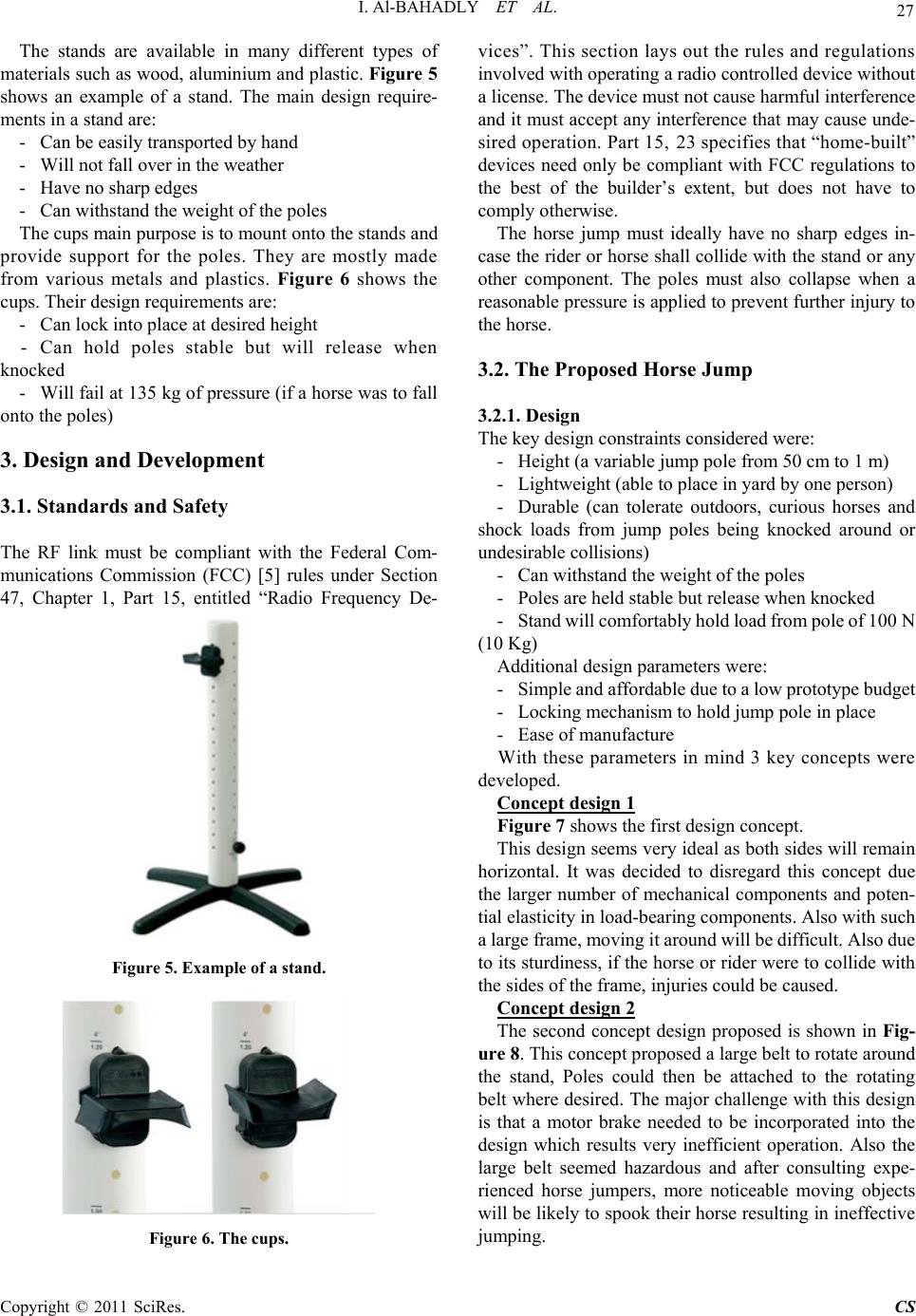 I. Al-BAHADLY ET AL. Copyright © 2011 SciRes. CS 27 The stands are available in many different types of materials such as wood, aluminium and plastic. Figure 5 shows an example of a stand. The main design require- ments in a stand are: - Can be easily transported by hand - Will not fall over in the weather - Have no sharp edges - Can wi thst an d t he weight o f t he poles The cups main purpose is to mount onto the stands and provide support for the poles. They are mostly made from various metals and plastics. Figure 6 shows the cups. Their design requirements are: - Can lock into place at desired height - Can hold poles stable but will release when knocked - Will fail at 135 kg of pressure (if a horse was to fall onto the poles) 3. Design and Development 3.1. Standards and Safety The RF link must be compliant with the Federal Com- munications Commission (FCC) [5] rules under Section 47, Chapter 1, Part 15, entitled “Radio Frequency De- Figure 5. Example of a stand. Figure 6. The cups. vices”. This section lays out the rules and regulations involved with operating a radio controlled device without a license. The device must not cause harmful interference and it must accept any interference that may cause unde- sired operation. Part 15, 23 specifies that “home-built” devices need only be compliant with FCC regulations to the best of the builder’s extent, but does not have to comply otherwise. The horse jump must ideally have no sharp edges in- case the rider or horse shall collide with the stand or any other component. The poles must also collapse when a reasonable pressure is applied to prevent furthe r injury to the horse. 3.2. The Proposed Horse Jump 3.2.1. Design The key design constraints considered were: - Height (a variable jump pole from 50 cm to 1 m) - Lightweight (a ble to place in yard by one person) - Durable (can tolerate outdoors, curious horses and shock loads from jump poles being knocked around or undesirable collisions) - Can wi thst an d t he weight o f t he poles - Poles are held stable but release when knocked - Stand will comfortably hold load from pole of 100 N (10 Kg) Additional design parameters were: - Sim ple and affor dable due to a low prototy pe budget - Locking mechanism to hold jump pole in place - Ease of manufacture With these parameters in mind 3 key concepts were developed. Concept design 1 Figure 7 shows the first design concept. This design seems very ideal as both sides will remain horizontal. It was decided to disregard this concept due the larger number of mechanical components and poten- tial elasticity in load-bearing components. Also with such a large frame, moving it around will be difficult. Also due to its sturdiness, if the horse or rider were to collid e with the sides of the frame, injuries could be caused. Concept design 2 The second concept design proposed is shown in Fig- ure 8. This concept proposed a large belt to rotate around the stand, Poles could then be attached to the rotating belt where desired. The major challenge with th is design is that a motor brake needed to be incorporated into the design which results very inefficient operation. Also the large belt seemed hazardous and after consulting expe- rienced horse jumpers, more noticeable moving objects will be likely to spoo k their horse resulting in ineffective jumping. 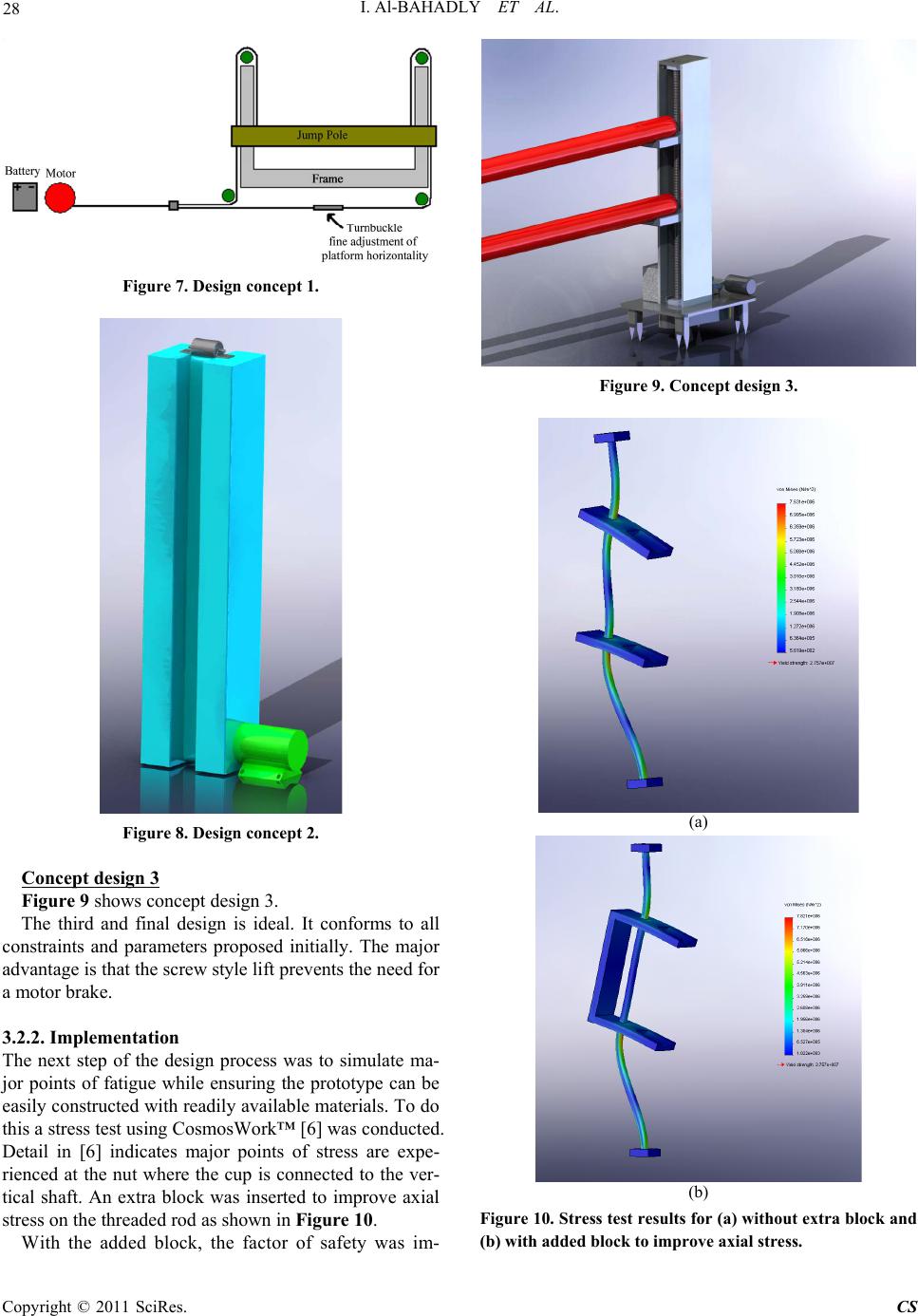 I. Al-BAHADLY ET AL. Copyright © 2011 SciRes. CS 28 Figure 7. Design concept 1. Figure 8. Design concept 2. Concept design 3 Figure 9 shows concept design 3. The third and final design is ideal. It conforms to all constraints and parameters proposed initially. The major advantage is that the screw style lift pr ev en ts the n eed for a motor brake. 3.2.2. Implementation The next step of the design process was to simulate ma- jor points of fatigue while ensuring the prototype can be easily constructed with readily available materials. To do this a stress test using CosmosWork™ [6] was conducted. Detail in [6] indicates major points of stress are expe- rienced at the nut where the cup is connected to the ver- tical shaft. An extra block was inserted to improve axial stress on the threaded rod as shown in Figure 10. With the added block, the factor of safety was im- Figure 9. Concept design 3. (a) (b) Figure 10. Stress test results for (a) without extra block and (b) with added block to improve axial stress. 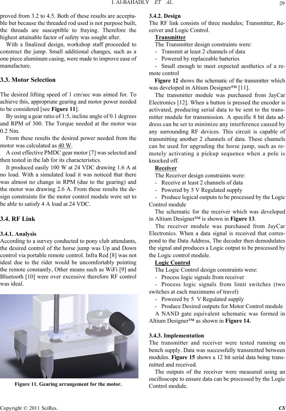 I. Al-BAHADLY ET AL. Copyright © 2011 SciRes. CS 29 proved from 3.2 to 4.5. Both of these results are accepta- ble but because the threaded rod used is not purpose built, the threads are susceptible to fraying. Therefore the highest attainable factor of safety was sought after. With a finalized design, workshop staff proceeded to construct the jump. Small additional changes, such as a one piece al uminum casing, were made to improve ease of manufacture. 3.3. Motor Selection The desired lifting speed of 1 cm/sec was aimed for. To achieve this, appropriate gearing and motor power needed to be considered [see Figure 11]. By u s in g a ge a r ra t i o o f 1 : 5 , i n c l i ne a ng l e o f 0 . 1 d eg r e e s and RPM of 300. The Torque needed at the motor was 0.2 Nm. From these results the desired power needed from the motor was calculated as 40 W. A cost effective PMDC gear m otor [7] was selected and then tested in the lab for its characteristics. It produced easily 100 W at 24 VDC drawing 1.6 A at no load. With a simulated load it was noticed that there was almost no change in RPM (due to the gearing) and the motor was drawing 2.6 A. From these results the de- sign constraints for the motor control module were set to be able to satisfy 4 A load at 24 VDC. 3.4. RF Link 3.4.1. Analysis According to a surv ey conducted to pony club attendants, the desired control of the horse jump was Up and Down control via portable remote control. Infra Red [8] was not ideal due to the rider would be uncomfortably pointing the remote constantly, Other means such as WiFi [9] and Bluetooth [10] were over excessive therefore RF control was ideal. Figure 11. Gearing arrangement for the motor. 3.4.2. Design The RF link consists of three modules; Transmitter, Re- ceiver and Logic Control. Transmitter The Transmitter design constrain ts were: - Transmit at least 2 ch annels of data - Powered by replaceable batteries - Small enough to meet expected aesthetics of a re- mote control Figure 12 shows the schematic of the transmitter w hic h was developed in Altium Designer™ [11]. The transmitter module was purchased from JayCar Electronics [12]. When a button is pressed the encoder is activated, producing serial data to be sent to the trans- mitter module for transmission. A specific 8 bit data ad- dress can be set to minimize any interferenc e caused by any surrounding RF devices. This circuit is capable of transmitting another 2 channels of data. These channels can be used for upgrading the horse jump, such as re- motely activating a pickup sequence when a pole is knocked off. Receiver The Receiver design constraints were: - Receive at least 2 channels of data - Powered by 5 V Regulated sup ply - P ro du ce log ic al o ut pu ts to b e p ro c es s ed by t he Log ic Control module The schematic for the receiver which was developed in Altium Designer™ is shown in Figure 13. The receiver module was purchased from JayCar Electronics. When a data signal is received that corres- pond to the Data Address, The decoder then demodulates the signal and pro duces a Lo gic out p ut to be pr ocessed by the Logic control module. Logic Control The Logic Control design constraints were: - Process logic signals from receiver - Process logic signals from limit switches (two switches a t each maximums of travel) - Powered by 5 V Regulated supply - Prod uce Desired outputs for M ot or Cont r ol module A NAND gate equivalent schematic was formed in Altium Designer™ as shown in Figure 14. 3.4.3. Implementation The transmitter and receiver were tested running on bench supply. Data was successfully tran smitted between modules. Figure 15 shows a 12 bit serial data being tr ans - mitted and received. The outputs of the receiver were measured using an oscilloscope to ensure data can be processed by the Logic Control module. 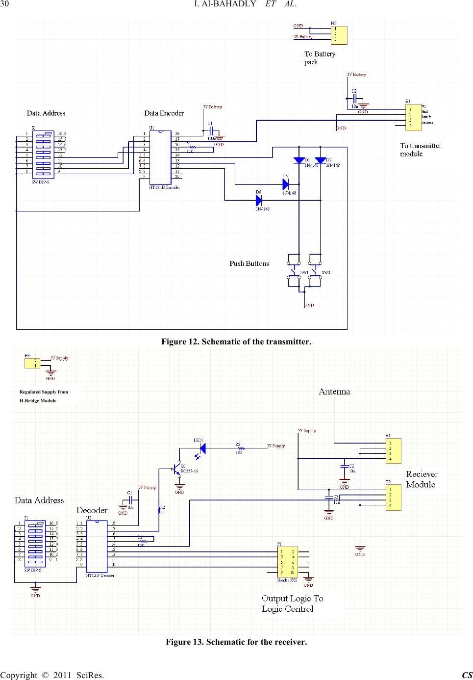 30 I. Al-BAHADLY ET AL. Copyright © 2011 SciRes. CS Figure 12. Schematic of the transmitter. Figure 13. Schematic for the receiver. Regulated Supply from H-Bridge Module 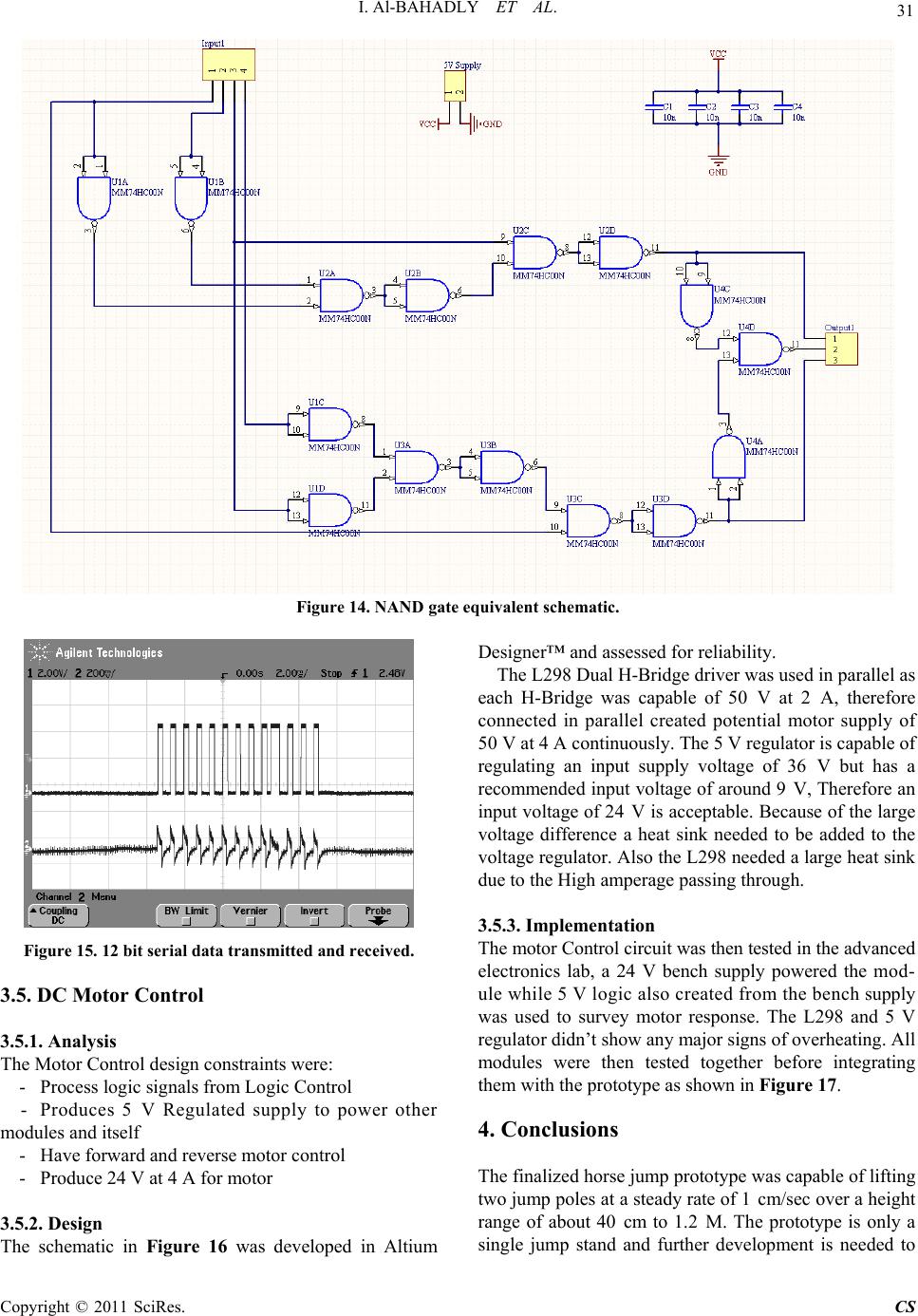 I. Al-BAHADLY ET AL. Copyright © 2011 SciRes. CS 31 Figure 14. NAND gate equivalent schematic. Figure 15. 12 bit serial data tr ansmitted and received. 3.5. DC Motor Control 3.5.1. Analysis The Motor Control design constraints were: - Process logic signals from Logic Control - Produces 5 V Regulated supply to power other modules and itself - Have forward and reve rse motor control - Produce 24 V at 4 A for motor 3.5.2. Design The schematic in Figure 16 was developed in Altium Designer™ and assessed for reliability. The L298 Dual H-Bridge driver was used in parallel as each H-Bridge was capable of 50 V at 2 A, therefore connected in parallel created potential motor supply of 50 V at 4 A continuously. The 5 V regulator is capable of regulating an input supply voltage of 36 V but has a recommended input vo ltage of around 9 V, Therefo re an input voltage of 24 V is acceptable. Because of the large voltage difference a heat sink needed to be added to the voltage regulator. Also the L29 8 needed a large heat sink due to the High amperage passing through. 3.5.3. Implementation The motor Control circuit was then tested in th e adv a n c ed electronics lab, a 24 V bench supply powered the mod- ule while 5 V logic also created from the bench supply was used to survey motor response. The L298 and 5 V regulator didn’t show any major signs of overheating. All modules were then tested together before integrating them with the prototype as shown in Figure 17. 4. Conclusions The finalized horse jump prototype was capable of lifting two jump poles at a steady rate of 1 cm/sec over a height range of about 40 cm to 1.2 M. The prototype is only a single jump stand and further development is needed to 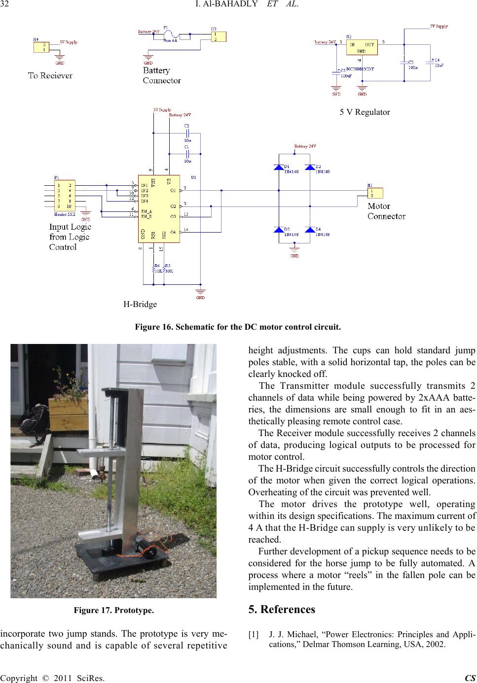 32 I. Al-BAHADLY ET AL. Copyright © 2011 SciRes. CS Figure 16. Schematic for the DC motor control circuit. Figure 17. Prototype. incorporate two jump stands. The prototype is very me- chanically sound and is capable of several repetitive height adjustments. The cups can hold standard jump poles stable, with a solid horizontal tap, the po les can be clearly knocked off. The Transmitter module successfully transmits 2 channels of data while being powered by 2xAAA batte- ries, the dimensions are small enough to fit in an aes- thetically pleasing remote control case. The Receiver module successfully receives 2 channels of data, producing logical outputs to be processed for motor control. The H-Bridge circuit successfully controls the direction of the motor when given the correct logical operations. Overheating of the circuit was prevented well. The motor drives the prototype well, operating wi th in its design specifications. The maximum current of 4 A that the H-Bridge can supply is very unlikely to be reached. Further development of a pickup sequence needs to be considered for the horse jump to be fully automated. A process where a motor “reels” in the fallen pole can be implemented in the fu ture. 5. References [1] J. J. Michael, “Power Electronics: Principles and Appli- cations,” Delmar Thomson Learning, USA, 2002. H-Bridge 5 V Regulator  I. Al-BAHADLY ET AL. Copyright © 2011 SciRes. CS 33 [2] J. W. Stewart and J. J. Mistovich, “The 8051 Microcon- troller: Hardware, Software and Interfacing,” 2nd Edition, Prentice Hall, New Jersey, 1998. [3] W. J. Eldon, “Boolean Algebra and Its Applications,” Dover Publications, USA, 2010. [4] M. Summers, “Building Showjumping Courses: A Guide for Beginners,” The Pony Club, 2006. [5] 2010. http://www.fcc.gov/ [6] 2010. http://www.solidworks.com/ [7] R. Krishnan, “Permanent Magnet Synchronous and Brushless Dc Motor Drives,” CRC Press, Boca Raton, 2009. doi:10.1201/9781420014235 [8] G. K. Shen, “Remote Control Using Inferared with Mes- sage Recording,” Master’s Thesis, Universiti Teknologi Malaysia, 2008. [9] J. Ross, “The Book of Wi-Fi: Install, Configure and Use 802.11 b Wireless Networking,” No Starch Press, USA, 2003. [10] D. D. M. Bakker and D. M. Gilster, “Bluetooth: End to End,” John Wiley & Sons, Inc., New York, 2002. [11] 2010. http://www.altium.com/products/altium-designer/ [12] 2010. http://www.jaycar.co.nz/ |