J. Electromagnetic Analysis & Applications, 2011, 3, 1-6
doi:10.4236/jemaa.2011.31001 Published Online January 2011 (http://www.SciRP.org/journal/jemaa)
Copyright © 2011 SciRes. JEMAA
1
The Influence of Electromagnetic Scattering from
a Permeable Sphere on the Induced Voltage across
a Rotating Eccentric Coil
Constantinos A. Valagiannopoulos
Department of Radio Science and Engineering, School of Electrical Engineering, Aalto University, Espoo, Finland.
Email: konstantinos.valagiannopoulos@aalto.fi
Received November 16th, 2010; revised December 20th, 2010; accepted December 27th, 2010.
ABSTRACT
Electromagnetic scattering and electromagnetic induction are research topics not directly associated to each other. In
this work, these two different concepts are combined in a model constituted by a rotating circular coil with a dielectric
spherical core at a fixed eccentric position. The scope of the analysis is to examine the effect of a permeable object on
the production of the alternating voltage. Methods and formulas from both scattering and induction have been utilized
for the derivation of the developed potential difference around the moving loop. Several graphs of the voltage output
with respect to the geometrical and material characteristics of the configuration, are presented and discussed.
Keywords: Electromagnetic Induction, Electromagnetic Scattering, Penetrable Dielectric Sphere, Rotating Loop
1. Introduction
The electromagnetic induction is defined as the develop-
ment of voltage across a closed conductor with time-
varying magnetic flux through it. The physics that govern
the inductive experiments have been mathematically
examined in a number of elementary treatises. The rela-
tionship between the various induction laws is summa-
rized in [1], where Cohn advocates that the combined use
of both motional and transformer induction assures the
validity of the produced results. A complete report re-
viewing the major developments and identifying impor-
tant trends in the broad field of geophysical electromag-
netic induction is given in [2]. Moreover, a rudimentary
study on induction inside a rotating coil surrounded by a
rigid conductor of finite or infinite extent has been pro-
vided in [3]. The analysis is based on integral solutions of
the field equations and leads to the conclusion that the
induced magnetic fields depend on the relative symmetry
of the rotator.
The electromagnetic scattering is defined as the modi-
fication of the incident field in the presence of an obsta-
cle through the fulfillment of the boundary conditions,
and numerous researches are performed on this topic. In
[4], the point-source scattering by an electrically large
conducting sphere has been discussed, where Bessel
functions of complex order are utilized. In addition, the
quasi-magnetostatic solution for a permeable prolate
spheroid under arbitrary excitation by a time-harmonic
primary field has been obtained by using the separation
of variables method with vector spheroidal wave func-
tions [5]. Finally in [6], a simplified solution is obtained
to the problem of a radiating loop in the presence of a
metallic core.
In this work, we combine the two aforementioned is-
sues (induction and scattering) by considering a structure
comprised of a rotating thin circular loop and an eccen-
trically positioned penetrable spherical core, illuminated
by a plane wave. The rotation happens around the eccen-
tric axis passing through the centre of the spherical cavity.
The magnetic vector potential at the position of the thin
closed wire is evaluated with use of spherical eigenfunc-
tion expansions and through the enforcement of the
boundary conditions. The variance of magnetic flux is
computed from the line integral of the electric field
around the metallic coil. The DC offset and the RMS
value of the produced voltage are represented in several
graphs with respect to the size of the sphere, the material
of the core and the excitation parameters as well. By in-
spection of the variations, one can reach various useful
and applicable conclusions. In particular, one can choose
the texture, the position and the radius of the scatterer
The Influence of Electromagnetic Scattering from a Permeable Sphere
2
on the Induced Voltage across a Rotating Eccentric Coil
that should be posed eccentrically inside the ring in order
to obtain maximum output voltage. The engineer could
utilize the dielectric core, when constructing an electro-
magnetic induction device, as an “optimizer” for regulat-
ing the produced potential.
2. Mathematical Concept
The configuration of the examined problem is shown in
Figure 1(a) where the spherical coordinate system (r, θ,
φ) and the equivalent Cartesian one (x, y, z) are also de-
fined. The origin O coincides with the center of a spheri-
cal volume (region 1) of radius a, filled with dielectric
material of relative permittivity ε1 and relative magnetic
permeability μ1. The scatterer is posed into vacuum (re-
gion 0) with intrinsic parameters (ε0, μ0). A thin circular
metallic loop of radius b > a, is shown on the x y plane,
with its center K at (x, y, z) = (0, d, 0) with b > d, located
eccentrically to the spherical core. The closed wire is
rotated with respect to x axis with circular frequency
in the presence of an x-polarized plane wave E0,inc, with
magnitude Q (in V/m), advancing towards the negative z
semi-axis. Mind that the harmonic time dependence of
the incident field, is of the form exp(–iω0t); it has circular
frequency ω0 ω. In Figure 1(b), we present a side view
of the device as appeared from the positive x semi-axis,
when the frame is rotated by angle ωt, at an arbitrary
time t.
ω
The polar radius R(φ) of the eccentric circular loop at t
= 0 (Figure 1(a)) is determined by applying the law of
cosines to the shaded triangle, yielding to:

222
sin cosRφdφbd φ . (1)
It is necessary to extract the parametric equation set of
the rotated coil denoted by

,, ,,xXφtyYφt
The azimuthal angle

,zZφt
0, 2φπ will play
the role of the parameterization variable even when the
object does not belong exclusively to x-y plane. At this
point, it is proper to make clear that there is no practical
importance in considering the filamentary loop as a torus
possessing non-negligible thickness. In the vast majority
of works concerning voltage production by electromag-
netic induction, the coil boundaries are constructed from
wires with infinitesimal transversal dimensions. Fur-
thermore, the assumed oscillation frequency is kept quite
low and thus the electrical size of the wire would be ex-
tremely small even it is not filamentary. In such a case,
the solution to the compound scattering problem from
both the dielectric sphere and the metallic torus would
lead to almost identical results to those assuming thin-
wire approximations.
As the closed wire is rotated with respect to x axis, the
corresponding coordinate X(φ, t) will be fixed, inde-
pendent from the angle ωt and equal to P(φ)cosφ. The
rest two equations are derived by projecting the other
edge of length P(φ)sinφ, positioned at angle ωt, upon the
axes x and z (see Figure 1(b)). Accordingly, one obtains
the following expressions:

,cXφtRφosφ (2a)
,sincoYφtRφφωts
(2b)
,sinsiZφtRφφωtn (2c)
The parametric representation of the curve in spherical
coordinates

,, Θ,, Φ,rPφtθφtφφt  for
each
0,φ 2π
, is given by:

Ρ,φtRφ
(3a)
Θ,arccos(sin sin)φtφωt (3b)
Φ,arctan(tan cos)φtφωt (3c)
According to Faraday’s law of induction [7], the in-
duced voltage across a closed metallic wire (W), is de-
fined as the line integral of the local electric field around
the loop. In case of a monochromatic electric field with
circular frequency ω0, the related formula is given below:

0
0
Re iωt
W
Ue d

EW
(4)
It should be stressed that E0 does not denote the real,
time-dependent electric field into vacuum, but the corre-
sponding complex phasor. In case the field quantities are
expressed in terms of the spherical coordinate system (r,
θ, φ), the Cartesian components are given by [8]:






0
0
0
0
0
0
,,
,,
,,
,,
cos sincos cossin
sinsinsincoscos, ,
cossin 0,,
x
y
z
r
θ
φ
Erθφ
Erθφ
Erθφ
Erθφ
φθφ θφ
φθφ θφErθφ
θθ Erθφ
















(5)
Once these functions are determined, the line integral
of (4) is particularized to give [9]:


0
2
000
0
Re,,, ,,,
π
iωt
xφyφzφ
Utee φtX φteφtY φteφtZ φtdφ




(6)
Copyright © 2011 SciRes. JEMAA
The Influence of Electromagnetic Scattering from a Permeable Sphere
3
on the Induced Voltage across a Rotating Eccentric Coil
E
0,inc
b + d
b + d
y
(φ = π/2)
x
(φ = 0)
ω
P
K
b
a
a O φ
d
z
R(φ)
(
ε
0
ε
1
, μ
0
μ
1
)
(ε
0
, μ
0
)
E
0,inc
b + d
z
(θ = 0)
ω
t
O
(
ε
0
ε
1
, μ
0
μ
1
)
(ε
0
, μ
0
)
b d
a
a
y
(θ = π/2)
x
(a) (b)
Figure 1. The physical configuration of the investigated device: (a) As viewed from the positive z semi-axis. (b) As viewed
from the positive x semi-axis. The red arrow denotes the moving direction of the incident plane wave, not the actual vector of
the electric field.
where subscript φ corresponds to the azimuthal partial
derivative of the related function. The small-e functions
000
,,
yz
eee are the electric field components evaluated
around the moving circular loop:


00
,Ρ,,Θ,,Φ,
xx
eφtE φtφtφt (7a)
 
00
,Ρ,,Θ,,Φ,
yy
eφtEφtφtφt
(7b)
 
00
,Ρ,,Θ,,Φ,
zz
eφtE φtφtφt (7c)
Thus, the only prerequisite to use expression (6) in
computing the induced voltage, is the explicit form of the
total electric field into vacuum, expressed in spherical
coordinates.
The electric field into vacuum background is com-
prised of the incident and the scattering component E0 =
E0,inc + E0,scat, where E0,inc = xQexp(-ik0z) and k0 =
000

. The electric field into vacuum region is com-
puted with use of spherical eigenfunctions and the follow-
ing series expansion [10]:
 
01
cos 0
0
1
21 cos
n
ik rθ
nn
n
einPθjkr


(8)
The symbol
m
n
Px corresponds to the Legendre
function of degree n, order m and argument x. The
spherical Bessel jn(x) and the spherical Hankel of the first
kind hn(x) are well-known [11]. The Riccati functions are
defined as
d
nn
zxdzxdx 

, where zn(x) is the
spherical Bessel or Hankel function. Once the boundary
conditions at r = a are imposed, the respective scattering
components of the electric field are given by:
 
0
1
0,
10
,,coscos n
rscat n
n
hkr
Erθφ QφSnP θkr

 (9a)
 







11
0
0, 0
10
cos cos
,, cos11sin
d
n
nn
θscat n
n
hkr
Sn dPθTnPθ
ErθφQφhkr
nn dθkrn nθ


 




(9b)
 







11
0
0, 0
10
cos cos
,, sin1sin 1
d
n
nn
φscat n
n
hkr
Sn PθTndPθ
ErθφQφhkr
nn θkrnndθ







(9c)
where:
  

 

110101
10101
21
dd
nnnn n
dd
nnn n
jkajkaεjkajka
Sninjkahkaεhkajka
  (10a)
 

 

10101
10101
21
dd
nnn n
n
dd
nnn n
jkajka μjkajka
Tn injkahka μhkajka
 (10b)
Copyright © 2011 SciRes. JEMAA
The Influence of Electromagnetic Scattering from a Permeable Sphere
4
on the Induced Voltage across a Rotating Eccentric Coil
The wavenumber in region 1 is defined by 10 11
k

.
As one can notice, the mathematical formulation
above is divided in two subsections; the first one con-
cerns the electromagnetic induction and the second one
examines the electromagnetic scattering. The induced
voltage around the loop (first subsection) is solely depen-
dent on the electromagnetic field and the shape/position
of the coil. Successful manipulation of the boundary
value scattering problem (second subsection) gives the
required electromagnetic field in explicit form. Accord-
ingly, there are two successive series of algebraic opera-
tions which help us understanding the combined induc-
tion/scattering consideration. In this sense, the two con-
cepts are not treated independently each other, because
the solution to the scattering problem is a prerequisite to
solving the induction one. That is why the dielectric core
cannot be present in our configuration, in case one ignores
the scattering procedure. In particular, the only mecha-
nism through which the permeable sphere participates in
the investigated context is the modification of the elec-
tromagnetic field externally to it.
It is also known [7] that the developed voltage around
a loop with area (S) is proportional to the time rate of
change of the magnetic flux through it, namely:

0
0
Re iωt
S
d
Ue
dt

 


BS
d
(11)
where Β0 is the magnetic field into vacuum. The area
integral above will be used alternatively for the evalua-
tion of the induced potential difference in order to vali-
date our results.
3. Numerical Results
Prior to proceeding to the numerical results, we should
determine the intervals into which the input parameters
belong. The radius of the metallic loop can take values
within the range 0.5 m < b < 2.5 m (in most cases equal
to b = 1 m). The frequency of the excitation wave is
moderate (usually equal to ω0 = 200π rad/sec), being
taken between the limits: 2π rad/sec < ω0 < 400π rad/sec.
When it comes to the spherical scatterer, its relative per-
mittivity does not affect substantially the results and thus
is kept constant throughout the numerical simulations (ε1
= 5). The relative magnetic permeability of the sphere
possesses usual magnitudes, that is 1 < μ1 < 2.5 and nor-
mally is assigned the value μ1 = 2. To the query “why
does the permeability vary?”, one shall respond that the
characteristics of the sphere’s material are treated as de-
grees of freedom in designing the device and therefore
can vary. As far as the values of μ1 are concerned, they
are chosen close to those owned by common composite
materials [12]. Instead of the radius of the sphere, we use
the normalized parameter
0,1abd as the core
should be kept internal to the rotating ring. The eccen-
tricity ratio
0,1dbd is also utilized to quantify
the relative transposition of the scatterer. In the following
graphs, two quantities are mainly represented; the DC
offset and the RMS value of the induced voltage, defined
below:

2
0
2
π
ω
dc
ω
UUt
π
dt
(12a)

2
2
0
2
π
ω
rms dc
ω
UUtU
π


dt
(12b)
The amplitude of the plane wave Q is a trivial parame-
ter and therefore is chosen high enough to give realistic
values for the output voltages.
In Figure 2(a), the RMS component of the produced
voltage is shown as function of the normalized sphere
0.1 0.2
0.3
0.4 0.5
0.6
0.7
0.8 0.9
normalized sphere radius a/(b d)
b= 0.5
m
b= 1.0
m
b= 1.5
m
b= 2.0
m
RMS voltage U
rms
(V)
1.4
1.2
1
0.8
0.6
0.4
0.2
0
(a)
0.1 0.2
0.3
0.4 0.5 0.6
0.7
0.8 0.9
normalized sphere radius a/(b d)
μ
1
= 1.0
μ
1
= 1.5
μ
1
= 2.0
μ
1
= 2.5
RMS voltage U
rms
(V)
0.31
0.3
0.29
0.28
0.27
0.26
0.25
0.24
0.23
(b)
Figure 2. The RMS induced voltage Urms as function of the
normalized radius of the spherical scatterer a/(b d), (a) for
various sizes of the loop b (μ1 = 2), (b) for various magnetic
permeabilities of the core μ1 (b = 1 m). Plot parameters: d =
0.2 m, ε1 = 5, ω = 200π rad/sec, ω0 = 200π rad/sec, Q = 105
V/m.
Copyright © 2011 SciRes. JEMAA
The Influence of Electromagnetic Scattering from a Permeable Sphere
5
on the Induced Voltage across a Rotating Eccentric Coil
radius for constant eccentric position d corresponding to
several sizes of the rotating loop. The maximum mag-
netic flux through the circular wire (and implicitly the
induced voltage) is proportional to the size of this ring.
Note also that the normalized radius of the sphere plays
rather unimportant role when it is kept low. On the con-
trary, when the scatterer gets close to the frame, there is
an amplifying effect on the measured quantity, which
gets more significant for larger loops. This is a natural
result because for fixed b,d, the available manoeuvring
area for the sphere to move gets restricted when the of
the loop is small. In Figure 2(b), the RMS value of the
produced voltage is represented with respect to the same
variable
abd for various magnetic permeabilities
of the sphere. One could also notice the exponentially
increasing behavior of the curves which remarks the
beneficial influence of the scatterer’s radius on the in-
duced voltage. In addition, this upward sloping trend is
proportional to the magnetic permeability of the spheri-
cal core, while there is no variation when the obstacle is
magnetically inert. In other words, the size and the mag-
netic density of the dielectric core provide the design
engineer with two additional degrees of freedom in con-
structing an efficient voltage generator.
In Figure 3, we show the measured response with re-
spect to the permeability of the core μ1, for several ec-
centricity ratios

dbd. It should be stressed that the
eccentricity ratio affects crucially the RMS value of the
induced voltage which means that the degree of asymme-
try reinforces the recorded quantity. In this way, the per-
meable sphere could play the role of a tuner with which
the magnitude of the output is chosen at will by changing
the eccentric position of the sphere. Also, all the curves
coincide at μ1 = 1 and then increase gradually for mag-
netically denser construction materials. It seems that
when μ1 = 1, the dielectric core becomes completely
transparent to the incident electromagnetic field regard-
less of its position.
In Figure 4(a), the RMS component of the produced
voltage is shown in a contour plot with respect to the
rotation frequency of the loop and the oscillation fre-
quency of the incident plane wave. For increasing ω0, the
recorded quantity gets reinforced with a pace negatively
related to ω. Once the rotation frequency gets larger,
there is either a stability in the measured output (modest
ω0) or a magnitude boost (substantial ω0). It should be
also remarked that when ω is very low, rapid variations
in Urms are observed for little change of ω0. This chaotic
behavior is attributed to the fact that, in case ω 0, the
magnetic flux is considerably affected even by the
slightest variance in the frequency of the alternating field.
In Figure 4(b), the DC offset Udc is represented for the
1
1.5
2
2.
5
core permeability μ
1
d
/(
b – a
) = 0.1
d
/(
b – a
) = 0.6
d
/(
b – a
) = 0.8
d
/(
b – a
) = 0.9
RMS voltage U
rms
(V)
0.2345
0.234
0.2335
0.233
0.2325
Figure 3. The RMS induced voltage Urms as function of the
core magnetic permeability μ1, for several eccentricity ra-
tios d/(
b
a). Plot parameters: a = 0.2 m, b =1 m, ε1 = 5, ω =
200π rad/sec, ω0 = 200π rad/sec, Q = 105 V/m.
rotation frequency ω (rad/sec)
200 400
600
800 1000 1200
0.7
0.6
0.5
0.4
0.3
0.2
0.1
1200
1000
800
600
400
200
excitation frequency ω
0
(rad/sec)
(a)
rotation frequency ω (rad/sec)
200 400
600
800
1000 1200
0.4
0.2
0
-0.2
-0.4
-0.5
1200
1000
800
600
400
200
excitation frequency ω
0
(rad/sec)
(b)
Figure 4. Contour plots of (a) the RMS induced voltage Urms
and (b) the DC component of the produced voltage Udc,
with respect to the rotation frequency ω and the excitation
frequency ω0. Plot parameters: a = 1/3 m, d = 1/3 m, b = 1 m,
ε1 = 5, μ1 = 2, Q = 105 V/m.
Copyright © 2011 SciRes. JEMAA
The Influence of Electromagnetic Scattering from a Permeable Sphere
on the Induced Voltage across a Rotating Eccentric Coil
Copyright © 2011 SciRes. JEMAA
6
same set of parameters. Note that in all the previous ex-
amples, the presence of the scatterer makes the produced
oscillating voltage to have nonzero average value owning
similar waveforms to Urms. This is not the case; when ω
is chosen close to ω0, there is a substantial increase for
growing frequencies. After numerical trials, we con-
cluded that the shape of the equal Udc levels in Figure
4(b) resemble rotated hyperbolas with narrow extent
following an asymptotic law of:
fundamental phenomena in electromagnetics (induction
and scattering) have not been studied yet.
The variation of the measured output is represented as
function of the sphere’s characteristic parameters and
several conclusions are drawn describing its effect on the
magnetic flux through the coil. An interesting expansion
of the present study would be to assume a spherical scat-
terer with inhomogeneities and/or anisotropies, or to
modify slightly the shape of the core using oblate sphe-
roid coordinates and functions. Also, closed wires of
arbitrary curvature rotating around arbitrary axes could
be also investigated with use of the same techniques.
22
0
3
5
2
dc
UOωωω ω




0
3
(13)
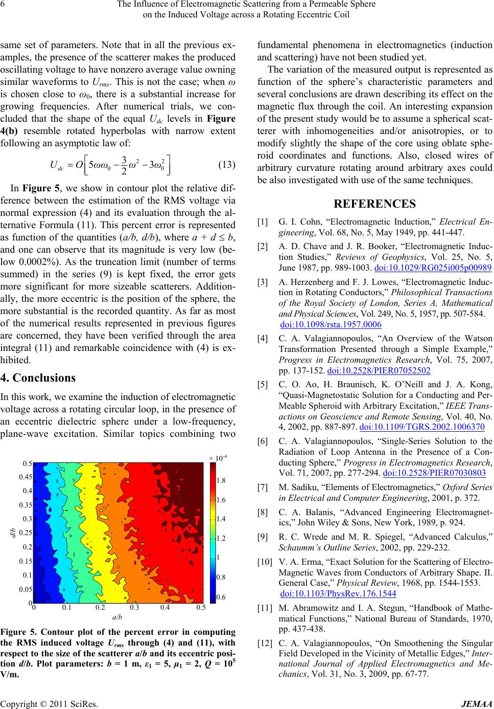
In Figure 5, we show in contour plot the relative dif-
ference between the estimation of the RMS voltage via
normal expression (4) and its evaluation through the al-
ternative Formula (11). This percent error is represented
as function of the quantities (a/b, d/b), where a + d b,
and one can observe that its magnitude is very low (be-
low 0.0002%). As the truncation limit (number of terms
summed) in the series (9) is kept fixed, the error gets
more significant for more sizeable scatterers. Addition-
ally, the more eccentric is the position of the sphere, the
more substantial is the recorded quantity. As far as most
of the numerical results represented in previous figures
are concerned, they have been verified through the area
integral (11) and remarkable coincidence with (4) is ex-
hibited.
REFERENCES
[1] G. I. Cohn, “Electromagnetic Induction,” Electrical En-
gineering, Vol. 68, No. 5, May 1949, pp. 441-447.
[2] A. D. Chave and J. R. Booker, “Electromagnetic Induc-
tion Studies,” Reviews of Geophysics, Vol. 25, No. 5,
June 1987, pp. 989-1003. doi:10.1029/RG025i005p00989
[3] A. Herzenberg and F. J. Lowes, “Electromagnetic Induc-
tion in Rotating Conductors,” Philosophical Transactions
of the Royal Society of London, Series A, Mathematical
and Physical Sciences, Vol. 249, No. 5, 1957, pp. 507-584.
doi:10.1098/rsta.1957.0006
[4] C. A. Valagiannopoulos, “An Overview of the Watson
Transformation Presented through a Simple Example,”
Progress in Electromagnetics Research, Vol. 75, 2007,
pp. 137-152. doi:10.2528/PIER07052502
4. Conclusions [5] C. O. Ao, H. Braunisch, K. O’Neill and J. A. Kong,
“Quasi-Magnetostatic Solution for a Conducting and Per-
Meable Spheroid with Arbitrary Excitation,” IEEE Trans-
actions on Geoscience and Remote Sensing, Vol. 40, No.
4, 2002, pp. 887-897. doi:10.1109/TGRS.2002.1006370
In this work, we examine the induction of electromagnetic
voltage across a rotating circular loop, in the presence of
an eccentric dielectric sphere under a low-frequency,
plane-wave excitation. Similar topics combining two [6] C. A. Valagiannopoulos, “Single-Series Solution to the
Radiation of Loop Antenna in the Presence of a Con-
ducting Sphere,” Progress in Electromagnetics Research,
Vol. 71, 2007, pp. 277-294. doi:10.2528/PIER07030803
a/b
0 0.1
0.2
0.3
0.4 0.5
1.8
1.6
1.4
1.2
1
0.8
0.6
0.5
0.45
0.4
0.35
0.3
0.25
0.2
0.15
0.1
0.05
0
d/b
×10
-
4
[7] M. Sadiku, “Elements of Electromagnetics,” Oxford Series
in Electrical and Computer Engineering, 2001, p. 372.
[8] C. A. Balanis, “Advanced Engineering Electromagnet-
ics,” John Wiley & Sons, New York, 1989, p. 924.
[9] R. C. Wrede and M. R. Spiegel, “Advanced Calculus,”
Schaumm’s Outline Series, 2002, pp. 229-232.
[10] V. A. Erma, “Exact Solution for the Scattering of Electro-
Magnetic Waves from Conductors of Arbitrary Shape. II.
General Case,” Physical Review, 1968, pp. 1544-1553.
doi:10.1103/PhysRev.176.1544
[11] M. Abramowitz and I. A. Stegun, “Handbook of Mathe-
matical Functions,” National Bureau of Standards, 1970,
pp. 437-438.
Figure 5. Contour plot of the percent error in computing
the RMS induced voltage U
rms through (4) and (11), with
respect to the size of the scatterer a/b and its eccentric posi-
tion d/b. Plot parameters: b = 1 m, ε1 = 5, μ1 = 2, Q = 105
V/m.
[12] C. A. Valagiannopoulos, “On Smoothening the Singular
Field Developed in the Vicinity of Metallic Edges,” Inter-
national Journal of Applied Electromagnetics and Me-
chanics, Vol. 31, No. 3, 2009, pp. 67-77.