Paper Menu >>
Journal Menu >>
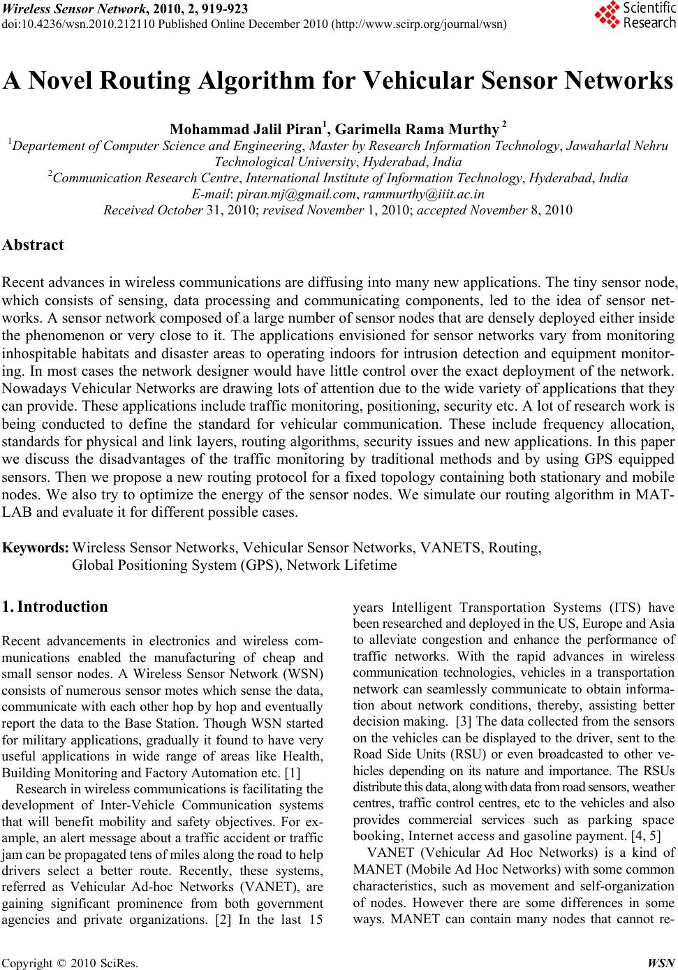 Wireless Sensor Network, 2010, 2, 919-923 doi:10.4236/wsn.2010.212110 Published Online December 2010 (http://www.scirp.org/journal/wsn) Copyright © 2010 SciRes. WSN A Novel Routing Algorithm for Vehicular Sensor Networks Mohammad Jalil Piran1, Garimella Rama Murthy 2 1Departement of Computer Science and Engineering, Master by Research Information Technology, Jawaharlal Nehru Technologic al Uni versi t y , Hyderabad, India 2Communication Research Centre, International Institute of Information Technology, Hyderabad, India E-mail: piran.mj@gmail.com, rammurthy@iiit.ac.in Received October 31, 2010; revised November 1, 2010; accepted November 8, 2010 Abstract Recent advances in wireless communications are diffusing into many new applications. The tiny sensor node, which consists of sensing, data processing and communicating components, led to the idea of sensor net- works. A sensor network composed of a large number of sensor nodes that are densely deployed either inside the phenomenon or very close to it. The applications envisioned for sensor networks vary from monitoring inhospitable habitats and disaster areas to operating indoors for intrusion detection and equipment monitor- ing. In most cases the network designer would have little control over the exact deployment of the network. Nowadays Vehicular Networks are drawing lots of attention due to the wide variety of applications that they can provide. These applications include traffic monitoring, positioning, security etc. A lot of research work is being conducted to define the standard for vehicular communication. These include frequency allocation, standards for physical and link layers, routing algorithms, security issues and new applications. In this paper we discuss the disadvantages of the traffic monitoring by traditional methods and by using GPS equipped sensors. Then we propose a new routing protocol for a fixed topology containing both stationary and mobile nodes. We also try to optimize the energy of the sensor nodes. We simulate our routing algorithm in MAT- LAB and evaluate it for different possible cases. Keywords: Wireless Sensor Networks, Vehicular Sensor Networks, VANETS, Routing, Global Positioning System (GPS), Network Lifetime 1. Introduction Recent advancements in electronics and wireless com- munications enabled the manufacturing of cheap and small sensor nodes. A Wireless Sensor Network (WSN) consists of numerous sensor motes which sense the data, communicate with each other hop by hop and eventually report the data to the Base Station. Though WSN started for military applications, gradually it found to have very useful applications in wide range of areas like Health, Building Monitoring and Factory Automation etc. [1] Research in wireless communications is facilitating the development of Inter-Vehicle Communication systems that will benefit mobility and safety objectives. For ex- ample, an alert message about a traffic accident or traffic jam can be pr opagated tens of mile s along the roa d to help drivers select a better route. Recently, these systems, referred as Vehicular Ad-hoc Networks (VANET), are gaining significant prominence from both government agencies and private organizations. [2] In the last 15 years Intelligent Transportation Systems (ITS) have been researche d and deploy ed in t he US, Europe and Asia to alleviate congestion and enhance the performance of traffic networks. With the rapid advances in wireless communication technologies, vehicles in a transportation network can seamlessly communicate to obtain informa- tion about network conditions, thereby, assisting better decision making. [3] The data collected from the sensors on the vehicles can be displayed to the driver, sent to the Road Side Units (RSU) or even broadcasted to other ve- hicles depending on its nature and importance. The RSUs distribute this data, along with data from road sensors, weather centres, traffic control centres, etc to the vehicles and also provides commercial services such as parking space booking, Internet access and gasoline payment. [4, 5] VANET (Vehicular Ad Hoc Networks) is a kind of MANET (Mobile Ad Hoc Networks) with some common characteristics, such as movement and self-organization of nodes. However there are some differences in some ways. MANET can contain many nodes that cannot re- 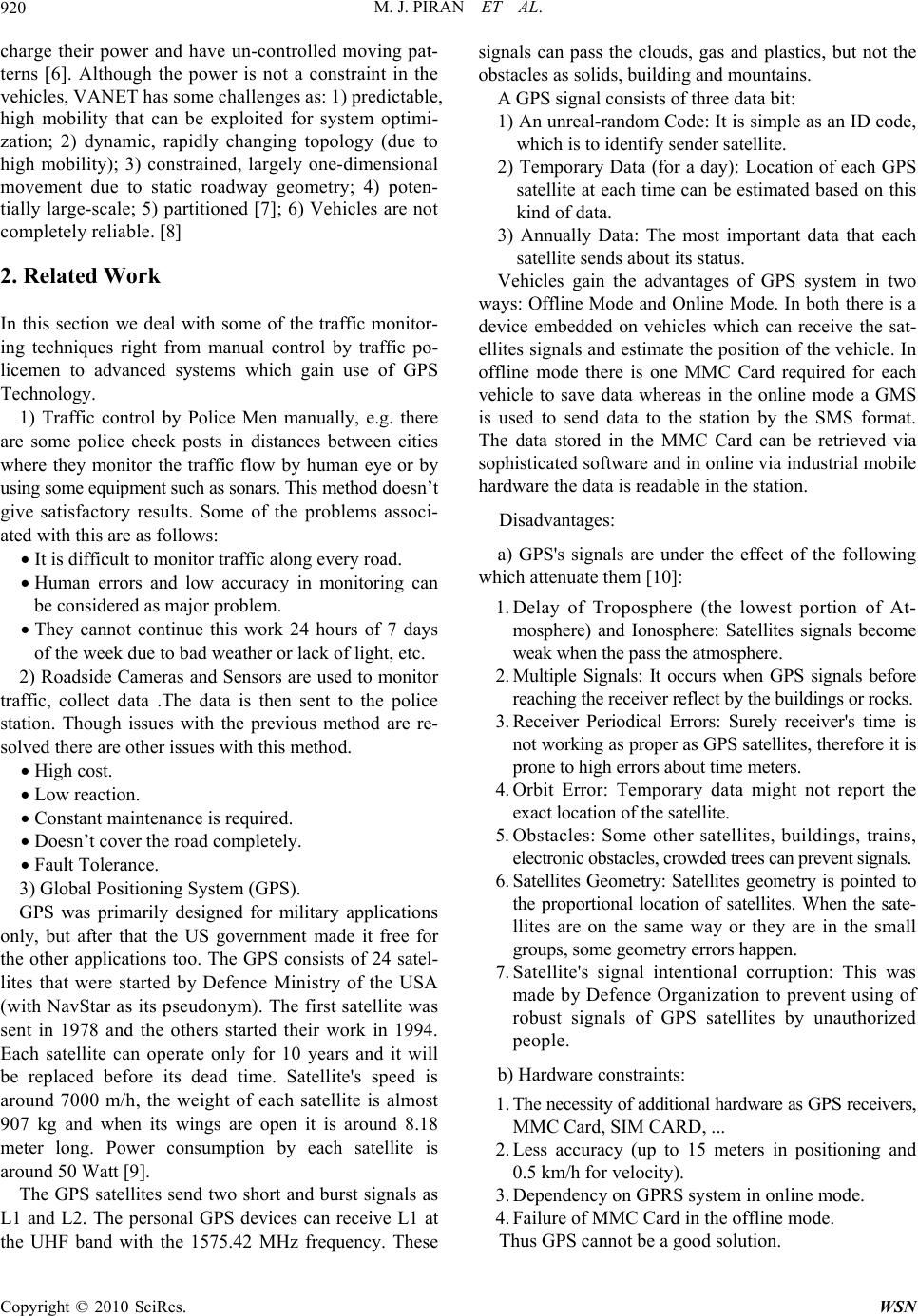 M. J. PIRAN ET AL. Copyright © 2010 SciRes. WSN 920 charge their power and have un-controlled moving pat- terns [6]. Although the power is not a constraint in the vehi c l es , V AN E T ha s s om e c ha l le n ge s as : 1 ) p re di c t ab le , high mobility that can be exploited for system optimi- zation; 2) dynamic, rapidly changing topology (due to high mobility); 3) constrained, largely one-dimensional movement due to static roadway geometry; 4) poten- tially large-scale; 5) partitioned [7]; 6) Vehicles are not comp le tel y reli ab le . [8] 2. Related Work In this section we deal with some of the traffic monitor- ing techniques right from manual control by traffic po- licemen to advanced systems which gain use of GPS Technology. 1) Traffic control by Police Men manually, e.g. there are some police check posts in distances between cities where they monitor the traffic flow by human eye or by using some equipment such as sonars. This method doesn’t give satisfactory results. Some of the problems associ- ated with this are as follows: It is difficult to monitor traffic along every road . Human errors and low accuracy in monitoring can be considered as major problem. They cannot continue this work 24 hours of 7 days of the week due to bad weather or lack of light, etc. 2) Roadside Cameras and Sensors are used to monitor traffic, collect data .The data is then sent to the police station. Though issues with the previous method are re- solved there are other issues with th is method. High cost. Low reaction. Constant maintenance is required. Doesn’t cover the road completely. Fault Tolerance. 3) Global Posit i oni n g Sy st em (GPS). GPS was primarily designed for military applications only, but after that the US government made it free for the other applications too. The GPS consists of 24 satel- lites that were started by Defence Ministry of the USA (with NavStar as its pseudonym). The first satellite was sent in 1978 and the others started their work in 1994. Each satellite can operate only for 10 years and it will be replaced before its dead time. Satellite's speed is around 7000 m/h, the weight of each satellite is almost 907 kg and when its wings are open it is around 8.18 meter long. Power consumption by each satellite is around 50 Watt [9]. The GPS satellites send two short and burst signals as L1 and L2. The personal GPS devices can receive L1 at the UHF band with the 1575.42 MHz frequency. These signals can pass the clouds, gas and plastics, but not the obstacles as solids, building and mountains. A GPS signal consists of three data bit: 1) An unreal-random Code: It is simple as an ID code, which is to identify sender satellite. 2) Temporary Data (for a day): Location of each GPS satellite at each time can be estimated based on this kind of data. 3) Annually Data: The most important data that each satellite sends about its status. Vehicles gain the advantages of GPS system in two ways: Offline Mode and On line Mode. In both there is a device embedded on vehicles which can receive the sat- ellites signals and estimate the position of the vehicle. In offline mode there is one MMC Card required for each vehicle to save data whereas in the online mode a GMS is used to send data to the station by the SMS format. The data stored in the MMC Card can be retrieved via sophisticated software and in onlin e via industrial mobile hardware the data is readable in the station. Disadvantages: a) GPS's signals are under the effect of the following which attenuate them [10]: 1. Delay of Troposphere (the lowest portion of At- mosphere) and Ionosphere: Satellites signals become weak when the pass the atmosphere. 2. Multiple Signals: It occurs when GPS signals before reaching the receiver reflect by the buildings or rocks. 3. Receiver Periodical Errors: Surely receiver's time is not working as proper as GPS satellites, therefore it is prone to high errors about t im e meters. 4. Orbit Error: Temporary data might not report the exact location of the satellite. 5. Obstacles: Some other satellites, buildings, trains, electronic obstacles , crowde d trees c an prev ent si gnals. 6. Satellites Geometry: Satellites geometry is pointed to the proportional location of satellites. When the sate- llites are on the same way or they are in the small groups, some geomet ry errors happen. 7. Satellite's signal intentional corruption: This was made by Defence Organization to prevent using of robust signals of GPS satellites by unauthorized people. b) Hardware constraints: 1. The necessity of additional hardware as GPS receivers, MMC Card, SIM CARD , ... 2. Less accuracy (up to 15 meters in positioning and 0.5 km/h for velocity). 3. Dependency on GPRS system in online mode. 4. Failure of MMC Card in the offline mode. Thus GPS cannot be a good solution. 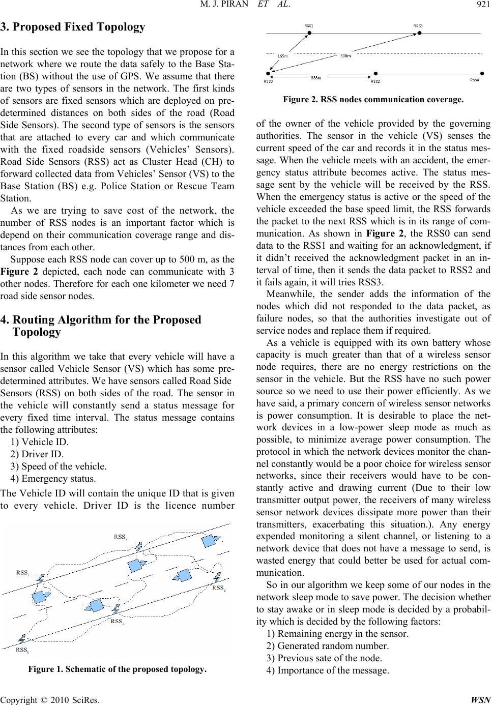 M. J. PIRAN ET AL. Copyright © 2010 SciRes. WSN 921 3. Proposed Fixed Topology In this section we see the topology th at we propose for a network where we route the data safely to the Base Sta- tion (BS) without the use of GPS. We assume that there are two types of sensors in the network. The first kinds of sensors are fixed sensors which are deployed on pre- determined distances on both sides of the road (Road Side Sensors). The second type of sensors is the sensors that are attached to every car and which communicate with the fixed roadside sensors (Vehicles’ Sensors). Road Side Sensors (RSS) act as Cluster Head (CH) to forward collected data from Vehicles’ Sensor (VS) to the Base Station (BS) e.g. Police Station or Rescue Team Station. As we are trying to save cost of the network, the number of RSS nodes is an important factor which is depend on their communication coverage range and dis- tances from each other. Suppose each RSS node can cover up to 500 m, as the Figure 2 depicted, each node can communicate with 3 other nodes. Therefore for each one kilometer we need 7 road side sensor nodes. 4. Routing Algorithm for the Proposed Topology In this algorithm we take that every vehicle will have a sensor called Vehicle Sensor (VS) which has some pre- determined attributes. We have sensors called Road Side Sensors (RSS) on both sides of the road. The sensor in the vehicle will constantly send astatus message for every fixed time interval. The status message contains the following attributes: 1) Vehicle ID. 2) Driver ID. 3) Spe ed of the vehicle. 4) Emergency status. The Vehicle ID will contain the unique ID that is given to every vehicle. Driver ID is the licence number Figure 1. Schematic of the proposed topology. Figure 2. RSS nodes communication coverage. of the owner of the vehicle provided by the governing authorities. The sensor in the vehicle (VS) senses the current speed of the car and records it in the status mes- sage. When the vehicle meets with an accident, the emer- gency status attribute becomes active. The status mes- sage sent by the vehicle will be received by the RSS. When the emergency status is active or the speed of the vehicle exceeded the base speed limit, the RSS forwards the packet to the next RSS which is in its range of com- munication. As shown in Figure 2, the RSS0 can send data to the RSS1 and waiting for an acknowledgment, if it didn’t received the acknowledgment packet in an in- terval of time, then it sends the data packet to RSS2 and it fails again, it will tries RSS3. Meanwhile, the sender adds the information of the nodes which did not responded to the data packet, as failure nodes, so that the authorities investigate out of service nodes and replace them if required. As a vehicle is equipped with its own battery whose capacity is much greater than that of a wireless sensor node requires, there are no energy restrictions on the sensor in the vehicle. But the RSS have no such power source so we need to use their power efficiently. As we have said, a primary concern of wireless sensor networks is power consumption. It is desirable to place the net- work devices in a low-power sleep mode as much as possible, to minimize average power consumption. The protocol in which the network devices monitor the chan- nel constantly would be a poor choice for wireless sensor networks, since their receivers would have to be con- stantly active and drawing current (Due to their low transmitter output power, the receivers of many wireless sensor network devices dissipate more power than their transmitters, exacerbating this situation.). Any energy expended monitoring a silent channel, or listening to a network device that does not have a message to send, is wasted energy that could better be used for actual com- munication. So in our algorithm we keep some of our nodes in the network sleep mode to save power. The decision whether to stay awake or in sleep mode is decided by a probabil- ity which is decided by the following factors: 1) Remaining energy in the sensor. 2) Generated random number. 3) Previous sate of the node. 4) Importance of t he m e ssag e. 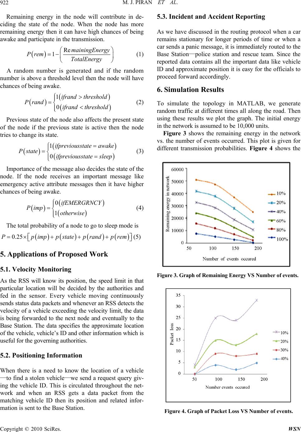 M. J. PIRAN ET AL. Copyright © 2010 SciRes. WSN 922 Remaining energy in the node will contribute in de- ciding the state of the node. When the node has more remaining energy then it can have high chances of being awake and participate in the transmission. Re 1mainingEnergy Prem TotalEnergy (1) A random number is generated and if the random nu mbe r is above a th reshold level then the node will hav e chances of being awake. 1 0 ifrand threshold Prand ifrand threshold (2) Previous state of the node also affects the present state of the node if the previous state is active then the node tries to change its state. 1 0 ifpreviousstate awake P stateifpreviousstatesleep (3) Importance of the message also decides the state of the node. If the node receives an important message like emergency active attribute messages then it have higher chances of being awake. 0 1 ifEMERGRNCY Pimp otherwise (4) The total probability of a node to go to sleep mode is 0.25Pp imppstatep randp rem (5) 5. Applications of Proposed Work 5.1. Velocity Monitoring As the RSS will know its position, the speed limit in that particular location will be decided by the authorities and fed in the sensor. Every vehicle moving continuously sends status data packets and whenever an RSS detects the velocity of a vehicle exceeding th e velocity limit, the da ta is being forwarded to the next node and eventually to the Base Station. The data specifies the approximate location of the vehicle, vehicle’s ID and other information which is useful for the governing authoriti es. 5.2. Positioning Information When there is a need to know the location of a vehicle —to find a stolen vehicle—we send a request query giv- ing the vehicle ID. This is circulated throughout the net- work and when an RSS gets a data packet from the matching vehicle ID then its position and related infor- mation is sent to the Base Station. 5.3. Incident and Accident Reporting As we have discussed in the routing protocol when a car remains stationary for longer periods of time or when a car sends a panic message, it is immediately routed to the Base Station—police station and rescue team. Since the reported data contains all the important data like vehicle ID and approximate position it is easy for the officials to proceed forward accordingly. 6. Simulation Results To simulate the topology in MATLAB, we generate random traffic at different times all along the road. Then using these results we plot the graph. The initial energy in the network is assumed to be 10,000 units. Figure 3 shows the remaining energy in the network vs. the number of events occurred. This plot is given for different transmission probabilities. Figure 4 shows the Figure 3. Graph of Remaining Energy VS Number of events . Figure 4. Graph of Packet Loss VS Number of events. 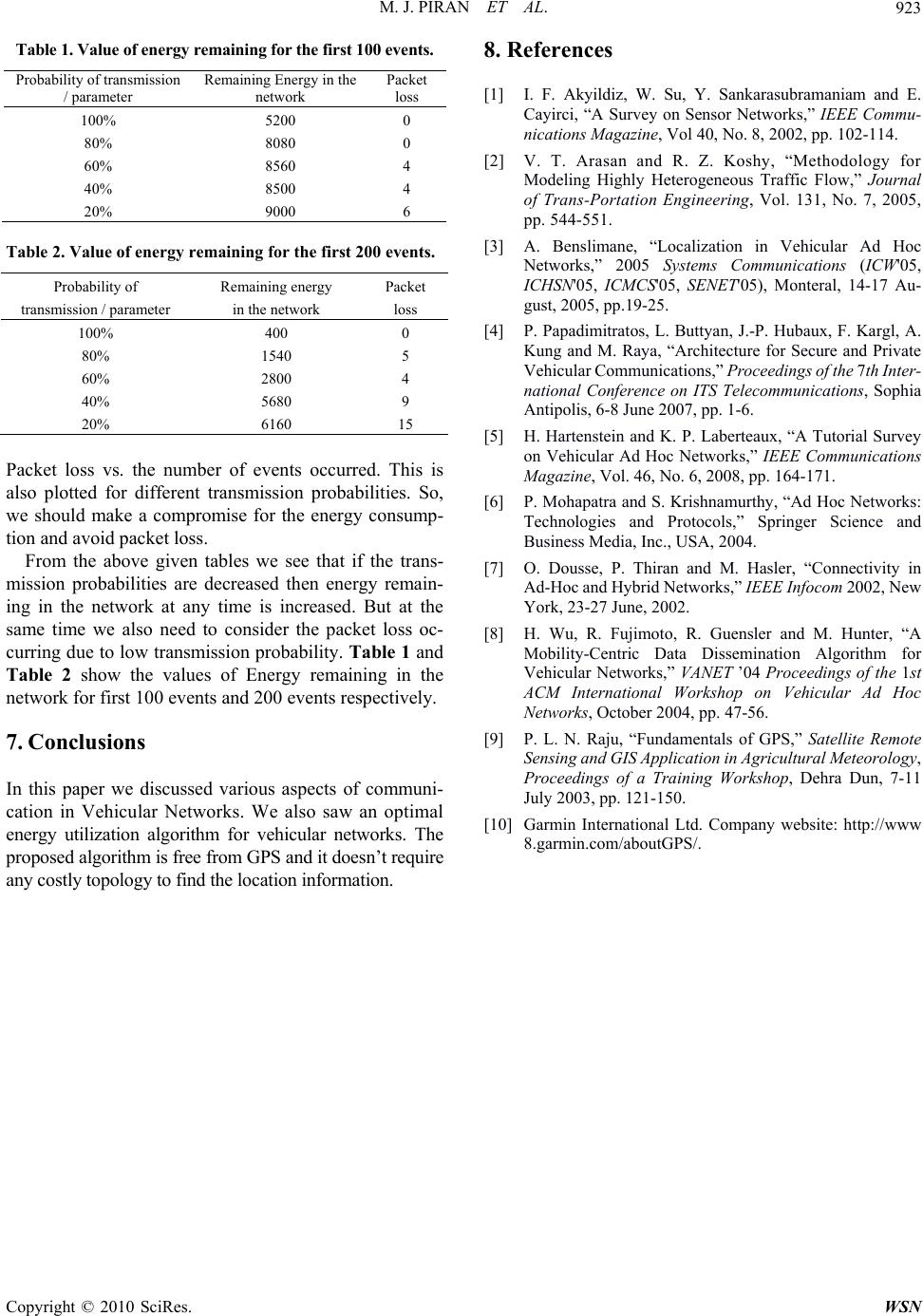 M. J. PIRAN ET AL. Copyright © 2010 SciRes. WSN 923 Table 1. Value of energy remaining for the first 100 events. Probability of transmission / parameter Remaining Energy in the network Packet loss 100% 5200 0 80% 8080 0 60% 8560 4 40% 8500 4 20% 9000 6 Table 2. Value of energy remaining for the first 200 events. Probability of transmission / parameter Remaining energy in the network Packet loss 100% 400 0 80% 1540 5 60% 2800 4 40% 5680 9 20% 6160 15 Packet loss vs. the number of events occurred. This is also plotted for different transmission probabilities. So, we should make a compromise for the energy consump- tion and avoid packet loss. From the above given tables we see that if the trans- mission probabilities are decreased then energy remain- ing in the network at any time is increased. But at the same time we also need to consider the packet loss oc- curring due to low transmission probability. Ta ble 1 and Table 2 show the values of Energy remaining in the network for first 100 events and 200 events respectively. 7. Conclusions In this paper we discussed various aspects of communi- cation in Vehicular Networks. We also saw an optimal energy utilization algorithm for vehicular networks. The proposed algorithm is free from GPS and i t doesn’t requi re any costly topology to fi nd the l ocati on inform ation. 8. References [1] I. F. Akyildiz, W. Su, Y. Sankarasubramaniam and E. Cayirci, “A Survey on Sensor Networks,” IEEE Commu- nications Magazine, Vol 40, No. 8, 2002, pp. 102-114. [2] V. T. Arasan and R. Z. Koshy, “Methodology for Modeling Highly Heterogeneous Traffic Flow,” Journal of Trans-Portation Engineering, Vol. 131, No. 7, 2005, pp. 544-551. [3] A. Benslimane, “Localization in Vehicular Ad Hoc Networks,” 2005 Systems Communications (ICW'05, ICHSN'05, ICMCS'05, SENET'05), Monteral, 14-17 Au- gust, 2005, pp.19-25. [4] P. Papadimitratos, L . Buttyan, J.-P. Hubaux, F. Kargl, A. Kung and M. Raya, “Architecture for Secure and Private Vehicular Communica tions,” Proceedings o f the 7th In ter- national Conference on ITS Telecommunications, Sophia Antipolis, 6-8 June 2007, pp. 1-6. [5] H. Hartenstein and K. P. Laberteaux, “A Tutorial Survey on Vehicular Ad Hoc Networks,” IEEE Communications Magazine, Vol. 46, No. 6, 2008, pp. 164-171. [6] P. Mohapatra and S. Krishnamurthy, “Ad Hoc Networks: Technologies and Protocols,” Springer Science and Business Media, Inc., USA, 2004. [7] O. Dousse, P. Thiran and M. Hasler, “Connectivity in Ad-Hoc and Hybrid Networks,” IEEE Info com 2 002, New York, 23-27 June, 2002. [8] H. Wu, R. Fujimoto, R. Guensler and M. Hunter, “A Mobility-Centric Data Dissemination Algorithm for Vehicular Networks,” VANET ’04 Proceedings of the 1st ACM International Workshop on Vehicular Ad Hoc Networks, October 2004, pp. 47-56. [9] P. L. N. Raju, “Fundamentals of GPS,” Satellite Remote Sensing and GIS Application in Ag ricultural M eteorology, Proceedings of a Training Workshop, Dehra Dun, 7-11 July 2003, pp. 121-150. [10] Garmin International Ltd. Company website: http://www 8.garmin.com/aboutGPS/. |