Vol.5, No.8A1, 63-71 (2013) Natural Science
http://dx.doi.org/10.4236/ns.2013.58A1008
Innovative earthquake resistant timber-glass
buildings
Bostjan Ber1, Miroslav Premrov2*, Iztok Sustersic3, Bruno Dujic3
1Kager Hisa d.o.o., Ptuj, Slovenia
2Faculty of Civil Engineering, University of Maribor, Maribor, Slovenia; *Corresponding Author: miroslav.premrov@um.si
3Contemporary Building Design, Celje, Slovenia
Received 13 June 2013; revised 13 July 2013; accepted 20 July 2013
Copyright © 2013 Bostjan Ber et al. This is an open access article distributed under the Creative Commons Attribution License,
which permits unrestricted use, distribution, and reproduction in any medium, provided the original work is properly cited.
ABSTRACT
Over the past decade the use of large size gla-
zing has increased with timber structures. Most
of the research works done so far have focused
on the building physics aspects of the glazing.
This paper, however, deals with the seismic be-
haviour of timber-glass systems. A series of
experiments were performed on the shaking ta-
ble of the IZIIS institute in Skopje, Macedonia.
One- and two-story full scale structures were
subjected to a series of ground motions, namely
sinus sweep testing, natural and modified ground
motion accelerograms. All together 8 different
setups were tested in elastic and inelastic be-
haviour range. Displacements and accelerations
were measured in each floor as well as the slip-
ping of walls, uplifting of their corners and the
shear deformation of the adhesive between the
glass panels and the timber frames. The tested
combination of timber-glass walls exhibited a
rocking type of behaviour, resulting in a de-
sirable ductile failure of steel hold-downs and
not brittle failure of the glazing nor failure of the
adhesive. Hence such a combination of glass
and timber in wall systems could potentially be
used in seismically a ctive areas.
Keywords: Timber; Glass; Seismic; Shake Table
Testing; Experimental Mechanics
1. INTRODUCTION
The use of timber in today’s contemporary housing is
increasing. It is a desirable building material due to its
low self-weight and high strength, hence making it espe-
cially suitable for seismically active areas. It is also an
ideal construction material from the perspective of envi-
ronmental impact and energy efficiency as it has very
low heat transmission, stores carbon dioxide and needs
very little energy for processing. Namely just the CO2
emissions in the processing of timber are approximately
two times lower that those present in manufacturing an
equivalent masonry element, three times lower than in
the case of a concrete element and six times lower than
emissions in steel element production. In addition one
cubic metre of timber (during growth) can store about
two tonnes of CO2, which no other building material is
capable of. Due to its properties timber walls can be
thinner than conventional walls from concrete or ma-
sonry and allow for a high degree of prefabrication,
hence speeding up the construction process.
On the other hand the use of glass as a building mate-
rial is still rather new. It has been extensively used for a
longer period in the form of builder’s joinery, namely
doors, partition walls, fences, facades etc. However the
concept of using glass for the main load bearing elements,
i.e. beams and columns, is rare. This is due to several
reasons, from the lack of building codes on one end to
the psychological effect of perceiving glass as a fragile
material on the other. The demand for the use of glass in
architecture is increasing though and several studies have
been performed over the past decade [1-12] to investi-
gate the possibilities of using glass for load bearing ele-
ments; either as a standalone material or in combination
with other materials.
In this paper we present the concept of using glass as a
horizontal seismic bracing element of timber frames.
Motivation, design concept and test results of shaking
table tests are presented in the following chapters.
1.1. Building Physics Concept
The design of modern houses is orientated towards a
high living quality and low energy consumption. Today
the architects are forced to orientate a house and its
Copyright © 2013 SciRes. OPEN ACCESS
B. Ber et al. / Natural Science 5 (2013) 63-71
64
transparent areas so that it makes the best use of natural
solar incomes. The latter is preconditioned by an appro-
priate size and orientation of the transparent areas, which
have to transmit an adequate amount of solar energy into
a building in order to assure natural lighting and heating
of interior space. Comparing transmission losses through
the building’s envelope and possible solar gains through
the glazing is of great importance to define the optimal
size of glazing areas and a suitable selection of glazing
type.
Respecting the aforementioned facts, the largest area
of the glazing in a building has to be orientated towards
south (for buildings in the northern hemisphere) [13].
Such placement of large glass areas (Figure 1) enables
better energy performance of a building, where the daily
obtained solar gains through the glazing can be evidently
higher than the transmission losses through these same
glazing areas throughout the night.
At the same time, however, this unfortunately leads to
specific technical challenges regarding the structural
behaviour of load bearing elements where the enlarged
size glazing is installed. This kind of construction sys-
tems can be, despite their energy efficiency, very prob-
lematic when a building is horizontally loaded.
1.2. Seismic Behaviour
Two typical horizontal load cases on a building are
wind and earthquake. Their load distributions over the
building height are somewhat similar although their ef-
fect on the building and their consequences are different.
Wind forces apply pressure on the outer walls of the
building, both pressure on the windward side and suction
on the leeward side. The global resultant of wind forces
of a building depends on its shape, regardless of the
building material. The seismic forces, however, affect the
building proportional to its mass distribution over the
floor plan and height as well as the stiffness distribution
of the buildings horizontal bracing elements (walls or
frames). For a majority of buildings on seismically active
Figure 1. Large size glazing on the southern facade.
areas the more problematic of the two is earthquake,
which subjects a building to a high intensity dynamic
load often resulting in catastrophic consequences. The
general principle when designing a building to resist
earthquakes is to take into account a certain level of
damage allowed to develop on structural elements during
an earthquake. As long as the story drifts are kept within
limited values the damage is allowed as it enables seis-
mic energy dissipation. However this damage may only
occur in elements that behave ductile, hence do not fail
brutally. This is the complete opposite to the general be-
haviour of glass, which is a strong, yet brittle material.
Hence the timber-glass building should be either de-
signed strong enough to withstand the seismic forces
undamaged or the glass elements should be protected
against too high forces by connecting it to the main
structure using ductile fasteners. Both principles are de-
scribed more in detail in the following chapters.
Another basic principle when designing a building to
resist seismic loads is trying to avoid plan irregularity.
This means that the building’s centre of mass and centre
of stiffness should be close together, hence avoiding the
unfavourable effects of torsion. Unfortunately, this is an
issue concerning energy efficient buildings that have
large glazing areas predominantly placed on southern
facades, hence resulting in an uneven stiffness over their
floor plan. As demonstrated in Figure 2 the centre of
mass is usually located about in the centre of a building.
The centre of stiffness, however, is placed closed to
the stiffer wall elements. As the centre of mass will yaw
around the centre of stiffness it will cause higher story
drifts on the glazing side causing an uneven distribution
of forces over the building’s floor plan. Hence the aim of
Figure 2. Centres of mass (G) and of stiffness (R) do not coin-
cide in a structure with stiffer walls on one side and more flexi-
ble frames on the other, hence causing a torsional behaviour of
a building.
Copyright © 2013 SciRes. OPEN ACCESS
B. Ber et al. / Natural Science 5 (2013) 63-71 65
this study was to investigate the possibility of using glass
panels as part of the façade’s glazing, to resist horizontal
loads caused by an earthquake.
2. WALL ELEMENTS
The main systems for resisting horizontal loads in
buildings are either walls or moment resisting frames.
Their behaviour is different for different boundary condi-
tions (geometry, vertical load on the structure, anchoring
etc.) and materials. Masonry and concrete walls of
course behave differently from timber walls, however all
timber walls do not behave in the same way as well.
Various systems are described more in detail in the next
chapter.
2.1. Timber Load Resisting Systems
There are various timber load resisting systems avai-
lable for building construction as demonstrated in Figure
3. These systems resist both vertical and horizontal loads.
However they all resist horizontal loads using different
principles for dissipating seismic energy. Bellow we only
describe the light timber frame system also used in the
experimental testing.
The light timber frame-panel wall system, analysed in
this research, originates from the Scandinavian-Ameri-
can construction methods where assembly work takes
place on-site. However the wall elements with a total
length of up to 12.5 meters are now entirely factory-
produced. Single wall panels are typically 1250 mm wide
and 2500 - 3100 mm high. They consist of a timber
frame (that resists the vertical load) and sheets of board-
material fixed by mechanical fasteners to one or both
sides of the timber frame. The sheathing resists the hori-
zontal loading. It is made from either oriented strand
board (OSB), plywood or even gypsum-fibre board. Fas-
teners that fix the sheeting to the frame (usually staples
or nails) must ensure a ductile failure mechanism also
enabling energy dissipation. Due to a large number of
such small fasteners such systems can dissipate a lot of
seismic energy, hence making them very earthquake effi-
cient. Design methods for such systems have been de-
veloped [14-17] however the European design codes still
do not offer any detailed seismic design guidance. On the
other hand other design standards, like the New Zealand
timber standard [18] provide methods for calculating the
exact stiffness of such walls based on several parameters
and taking into account various boundary conditions.
2.2. Glass Walls Concept
Combining timber and glass to get an appropriate
load-bearing element is a challenging process. We are
combining two materials with rather different character-
istics. Namely, the external timber-glass wall elements
Figure 3. Different timber load resisting systems; log house (a);
light timber frame (b); post and beam (c); massive cross lami-
nated timber panels (d).
will be mostly placed in the south. Hence, they will be
exposed to high temperature differences. Unfortunately,
the coefficients of thermal linear expansion (αt) of timber
and glass are quite different (almost a factor of two in the
grain direction). Perpendicular to the grain, the coeffi-
cient of thermal expansion for timber is as much as ten
times larger than the coefficient parallel to grain, Hoad-
ley [19]. That is almost twenty times lower than for glass.
Consequently, temperature differences can cause high
shear stresses in the adhesive between the timber frame
and the glass panels.
There are numerous parameters, which influence the
horizontal resistance and stiffness of the timber-glass
wall elements, i.e. material properties and thickness of
glass panes. However, the connection between timber
and glass is one of the most important. The following
connection parameters have a significant influence on the
response of timber glass walls (if the glass is glued to
timber): 1) the position of the glass pane and hence the
position of the glue line; 2) the type of the adhesive and
3) the thickness and width of the glue line.
The aforementioned parameters have been studied by
several authors; Niedermaier [1], Kreuzinger & Nieder-
maier [2], Holzforshung Austria [3], Cruz et al. [4], Bly-
berg [5], Ber et al. [6] and Schober [7] experimentally
and numerically as well.
As discussed in chapter 1.2 one of the possibilities for
using a fixed glazing in prefabricated timber-frame panel
wall elements is to replace the classical sheathing boards
with the glass panes (as schematically presented in Fig-
ure 4). The glass panes need to be sufficiently over-
strengthened (relative to the metal fasteners that connect
them to the timber frame) to ensure that a ductile failure
mechanism forms in the connection between the glass
and the frame.
However the other option is to connect the glass pan-
Copyright © 2013 SciRes. OPEN ACCESS
B. Ber et al. / Natural Science 5 (2013) 63-71
66
els to the main timber frame without the use of ductile
fasteners (using an adhesive instead) and to sufficiently
dimension the glass panels to resist the seismic forces in
an elastic state.
This is not the standard-recommended approach as it
can still result in brittle failure however several timber
house producers already install their glazing using such a
principle. They do use other design principles of resisting
the horizontal load (i.e. installing moment resisting
frames around the glass panes). So far, the contribution
of the glass to lateral resistance and stiffness of the tim-
ber-frame wall elements has been neglected. However
the glass panes have a substantial influence of the build-
ings behaviour. Hence, analysing the behaviour of such
panels was the main aim of our experimental study.
3. EXPERIMENTAL ANALYSIS
So far a number of studies on combining glass with
timber were performed, some of them also focused on
the in-plane load-bearing capacity of glass panes [1-7,
11,12]. However, the research presented in the following
chapters was not limited to investigating the in-plane
load-bearing capacity of glass panes under a monotonic
or cyclic static load. The experimental testing was fo-
cused on the load-bearing capacity of one- and two-story
timber-glass buildings under a dynamic shaking table
induced load.
3.1. Test Wall Specimens
Timber-glass wall elements consisted of timber frames
with the outside edges measuring 2.4 × 2.4 m, which is a
standard size for testing the racking strength of light
timber frame wall panels according to EN 594 [20]. Di-
mensions of timber stud cross sections were 160160
mm. The dimensions of the top beam cross section
(width/height) were 80280 mm and the dimensions of
Figure 4. Timber-glass prefabricated walls; replacing classical
sheathing boards with glass panes.
the bottom sill were 160120 mm. The isolative glass
panels were made from three 6 mm glass panes. The ad-
hesive layer made from one-component polyurethane
was 5 mm thick.
Timber frames were made of GL24 h grade timber ac-
cording to EN 1194 [21]. Triple insulation glass panes
were made of float glass and the adhesive used in the
timber-glass joint was a one-component polyurethane
adhesive, type Ködiglaze P produced by Kömmerling.
The material properties of float glass were taken from
EN 572-1 [22], and material properties of adhesives were
obtained from the producer’s technical sheet [23]. All
material properties are listed in Table 1 and the adhesive
stress-strain curve is presented in Figure 5.
Light timber frame wall elements with OSB sheathing
were also used with the tested specimens. They consisted
of a timber frame and 12 mm thick OSB sheathing sta-
pled onto the timber frame. Dimensions of timber studs,
top and bottom sills were 80100 mm. Four different
walls types were used for the assembly of the tested
specimens (Figure 6). “TGWE1” represents a timber
frame with one large glass panel. “TGWE2” represents a
timber frame with two smaller glass panels divided by an
additional stud in the middle. “LTFWE1” represents a
large timber frame wall element with two OSB sheathing
Figure 5. Stress-strain diagram of one-
component polyurethane adhesive.
Table 1. Properties of the materials used.
Timber fram e GL24 h Float glass EN 572-1
E0,m
[N/mm2] 11,600 70,000
Gm
[N/mm2] 720 28,455
fm,k
[N/mm2] 24 45
ft,0,k
[N/mm2] 16.5 45
fc,0,k
[N/mm2] 24 500
ρk
[kg/m3] 380 2500
Copyright © 2013 SciRes. OPEN ACCESS
B. Ber et al. / Natural Science 5 (2013) 63-71
Copyright © 2013 SciRes.
67
Figure 6. Dimensions of timber-glass and light timber frame wall elements.
circumferentially around the glass panel into a groove in
the timber frame. The choice of the adhesive and the
glass type, was based on the test results of previously
done monotonic static tests of glass-timber panels with
single pane glazing [6].
Figure 7. The connection detail between the timber frame and
the glass panel. 3.2. Test Building Configurations
Four single-storey and four two-storey structures
combining different types of wall elements with ground
plane dimension of 2.4 × 3.4 m were tested on the shak-
ing table. 100 mm thick cross laminated (XLam) timber
floor slabs were used and an additional mass of 1600 kg
was installed on every floor. Single-storey setups had a
total height of 2.5 m, two-storey setups reached exactly 5
m in height (Figure 8). It should be noted however that
the XLam slabs were transferring a majority of the verti-
cal load of the floor onto the walls perpendicular to the
excitation direction. The walls loaded in plane hence had
minimal vertical load applied on top. That is an impor-
tant boundary condition that affects the seismic behav-
iour of the respective walls.
Wall elements were anchored with hold-downs WKR
285 in the corners (Figure 9) and with shear angular
brackets WKR 135 installed at every 800 mm (centre to
centre) along the bottom sill. The floor plates were con-
nected to the bottom walls with self-tapping 8 mm di-
ameter screws (180 mm long) at a distance of 150 mm
centre to centre. Top and bottom walls were vertically
anchored by hold-downs in the corners with 12 mm di-
ameter bolts (Figure 9). The upper walls were also con-
nected to the floor slab with shear angular brackets. The
latter were fixed to the slab using self-tapping screws.
Figure 8. Dimensions of one- and two-storey test mod-
els.
boards (installed from one side) measuring 2.4 × 2.4 m
while “LTFWE2” represents a small timber frame wall
element with one OSB sheathing board measuring 1.2 ×
2.4 m.
Various combinations of one- and two-story structures
were tested (Figures 10, 11) by combining different wall
setups; namely large and small glass panes and combin-
ing LTF and TGW walls to elicit torsional behaviour of
the building. Four accelerometers and two potentiome-
ters were placed in each floor for measuring the accelera-
A special connection detail (Figure 7) was used to
bond the timber frames and the glass panels together. A
50 mm wide and 5 mm thick adhesive layer was applied
OPEN ACCESS
B. Ber et al. / Natural Science 5 (2013) 63-71
68
(a)
(b)
Figure 9. Steel hold-downs placed in the
corners of walls in the ground floor and
anchored into the RC foundation (a) and
the vertical anchoring between wall pan-
els of the ground and first floor (b).
tions in all directions and displacements in the excitation
direction. To analyse the failure mechanisms setups
GLS5 and GLS10 had additional instrumentation for
measuring slips in the connection planes (timber-timber
and timber-glass) and the uplifting of wall corners in-
stalled.
3.3. Loading Protocol
The testing series was divided into two basic modules;
1) low-intensity testing where the structure remained
undamaged and in an elastic state of the material behav-
iour (including all the connections) and 2) high-intensity
testing where the ground acceleration was scaled up
enough to cause failure in the structure. Before and after
Figure 10. Configuration of one-story test models.
Figure 11. Configuration of two-story test
models.
each earthquake simulation a sine sweep test (frequen-
cies in the range of 1 - 32 Hz, acceleration intensity of
0.01 g) was performed in order to clearly calculate the
vibration period of the structure. The sinus test was fol-
lowed by a series of scaled modified accelerograms of
the Landers earthquake.
The accelerogram was modified in a way to excite a
broad spectrum of vibration periods namely to affect all
types of structures regardless of their stiffness as shown
on the comparison of the accelerogram’s elastic spectra
(with 5% damping) to the standard Eurocode 8 elastic
spectra in Figure 12. In addition to the modified scaled
Landers accelerogram also sine-beat loads were applied
Copyright © 2013 SciRes. OPEN ACCESS
B. Ber et al. / Natural Science 5 (2013) 63-71 69
Figure 12. Comparison of the elastic response spectra of the
modified Landers accelerogram and the standard Eurocode 8
spectra, both with 5% damping.
Table 2. The applied loading protocol.
Low-intensity testing
GLS1-GLS4 and GLS6-GLS9
modified Landers 0.15 g
modified Landers 0.25 g
Petrovac 0.22 g
High-intensity testing
GLS5
modified Landers 0.50 g
modified Landers 0.75 g
sine-beat 9.856 Hz 0.10 g
sine-beat 9.856 Hz 0.50 g
sine-beat 9.856 Hz 1.00 g
random 2 - 15 Hz 0.10 g
random 2 - 15 Hz 0.25 g
random 2 - 15 Hz 0.40 g
GLS10
modified Landers 0.50 g
modified Landers 0.75 g
random 2 - 15 Hz 0.25 g
random 2 - 15 Hz 0.35 g
to the one-story structure. Namely 3 single-beats at 9.856
Hz (the 1st vibration frequency of the tested structure
configuration) scaled up to 0.40 g. They were followed
by a randomly generated varying (2 - 15 Hz) sinus
ground motion scaled up to 0.40 g for one-story and up
to 0.35 g for two-story specimens. The whole list of ap-
plied ground motions is specified in Table 2.
For the low-intensity testing also the Petrovac acce-
lerogram was used. However for the high intensity test-
ing also sine-beats with the first frequency of the struc-
ture were applied as well as random sinus tests with fre-
quencies raging in the from 2 to 15 Hz. The results are
discussed in the next chapter.
Figure 13. Vibration periods for one-story models.
Figure 14. Vibration periods for two-story models.
3.4. Results and Discussion
Diagrams of first frequencies and first periods are
shown in Figures 13 and 14.
After being subjected to the recorded (Petrovac) and
modified (Landers) accelerograms the structures did not
exhibit any serious damage. To intensify the response of
the structure a randomly generated ground motion with
the frequency range of 2 - 15 Hz peak ground accelera-
tion up to 0.4 g was applied. Deformations in the adhe-
sive joint between the glass panel and the timber frame
as well as slip of the entire timber frame and uplift at the
corners were visible. They are presented in Figure 15 for
the specimen GLS10 and the random excitation with a
0.35 g peak acceleration.
During the high-intensity testing the walls exhibited a
rocking-type of behaviour with uplifting at the corners
(0.6 to 0.8 mm) and minor slip of the walls in the ground
floor (0.15 to 0.2 mm). Most of the seismic energy was
dissipated in the steel connections without any damage in
the glass. A shear slip of 1 to 1.5 mm was present in the
adhesive between the glass panel and the timber frame,
however seal remained undamaged.
The timber-glass walls have 5 theoretically possible
failure modes (Figure 16) when loaded in-plane: (1) fail-
ure of corner hold-downs; (2) failure of shear brackets;
(3) failure of the adhesive joint between glass and timber;
(4) failure of the glass panel and (5) failure of the col-
umns. The tested walls demrated a desirable rock onst
Copyright © 2013 SciRes. OPEN ACCESS
B. Ber et al. / Natural Science 5 (2013) 63-71
Copyright © 2013 SciRes.
70
(a)
(b)
(c)
Figure 15. LVDT measurements of the shear displacement in the adhesive line between timber and glass (a),
shear slip of a wall (b) and corner uplift of a wall (c).
ure mechanism (1) was established in the steel hold-
downs. It should be noted that a low vertical load on the
bracing walls had an influence on the development of a
rocking mechanism. With a higher vertical load the shear
behaviour of the glass panels would be activated, hence
increasing the stresses in the shear brackets, the adhesive
and the glass.
4. CONCLUSIONS
Four single-story and four two-story timber-glass
structures combining different types of timber-frame wall
elements with fixed glazing were tested. The tested
specimens exhibited a rocking type of behaviour, dissi-
pating the seismic energy in the corner hold-downs. The
shear slip of the panels in the ground floor was minimal.
The shear slip in the adhesive line was present however
no damage occurred.
Figure 16. Theoretically possible fail-
ure modes; mode (1) was activated
during testing.
The experimental results present a good starting point
for a future parametric FEM study. The latter will pro-
vide a more comprehensive understanding of the influ-
ing-type of behaviour without any residual deformations
in the adhesive joint and the timber frame. A ductile fail-
OPEN ACCESS
B. Ber et al. / Natural Science 5 (2013) 63-71 71
ence that different types and dimensions of the glazing
and different types of adhesives have on the seismic re-
sponse of timber-glass structures.
5. ACKNOWLEDGEMENTS
The support of the companies Gozdno gospodarstvo Slovenj Gradec,
Reflex, Kager hisa, Ko-glas, Kömmerling, Rothoblaas and Storaenso
who donated the materials needed for the experiments is gratefully
acknowledged. The research support provided by the EU through the
European Social Fund “Investing in your future” is also acknowledged.
REFERENCES
[1] Niedermaier, P. (2003) Shear-strength of glass panel ele-
ments in combination with timber frame constructions.
Proceedings of the 8th International Conference on Ar-
chitectural and Automotive Glass (GPD), Tampere, 15-18
June 2003, 262-264.
[2] Kreuzinger, H. and Niedermaier, P. (2005) Glas als
Schubfeld. Tagungsband Ingenieurholzbau, Karlsruher
Tage.
[3] Holzforshung Austria (2008) Holz-glas-verbundkons-
truktionen, weiterentwicklung und herstellung von holz-
glas-verbundkonstruktionen durch statisch wirksames
verkleben von holz und glas zum praxiseinsatz im holz-
hausbau (impulsprojekt V2 des kind holztechnologie).
Endbericht, Vienna.
[4] Cruz, P., Pequeno, J., Lebet. J.P. and Močibob, D. (2010)
Mechanical modelling of in-plane loaded glass panes.
Challenging Glass 2—Conference on Architectural and
Structural Applications of Glass, Delft, 20-21 May 2010,
309-319.
[5] Blyberg, L. (2011) Timber/glass adhesive bonds for
structural applications. Licentiate Thesis by Louise Bly-
berg, Linnaeus University, School of Engineering, Swe-
den.
[6] Ber, B., Premrov, M. and Kuhta, M. (2012) Horizontal
load-carrying capacity of timber-framed walls with glass
sheathing in prefabricated timber construction. Proceed-
ings of the 34th Assembly of Structural Engineers of Slo-
venia, Bled, 11-12 October 2012, 211-218.
[7] Schober, K.P., Leitl, D. and Edl, T. (2006) Holz-glas-
verbundkonstruktionen zur gebäudeaussteifung, magazin
für den holzbereich. Heft 1, Holzforschung Austria, Vien-
na.
[8] Wellershoff, F. (2006) Nutzung der verglasung zur aus-
steifung von gebäudehüllen. Ph.D. Thesis, Schriftenreihe-
Stahlbau RWTH Aachen, Heft 57, Shaker Verlag, Aachen.
[9] Mocibob, D. (2008) Glass panel under shear loading—
Use of glass envelopes in building stabilization. Ph.D.
Thesis, École Polytechnique Fédérale de Lausanne, Thèse
No. 4185, Lausanne.
[10] Huveners, E.M.P. (2009) Circumferentially adhesive
bonded glass panes for bracing steel frames in facades.
Ph.D. Thesis, University of Technology Eindhoven, Eind-
hoven.
[11] Rajcic, V. and Zarnic, R. (2012) Racking performance of
wood-framed glass panels. The future of timber engi-
neering. World Conference on Timber Engineering,
Auckland, 15-19 July 2012, 57-56.
[12] Rajcic V. and Zarnic R. (2012) Seismic response of tim-
ber frames with laminated glass infill. Proceedings of the
45th CIB-W18 Meeting, August 2012, Växjö, Paper 45-
15-4.
[13] Zegarac L.V. and Premrov, M. (2011) An approach in
architectural design of energy-efficient timber buildings
with a focus on the optimal glazing size in the south-ori-
ented façade. Energy and Buildings, 43, 3410-418.
doi:10.1016/j.enbuild.2011.09.003
[14] Kozem S.E., Premrov, M. and Silih, S. (2012) Numerical
analysis of timber-framed wall elements coated with sin-
gle fibre-plaster boards. Engineering Structures, 41, 118-
125. doi:10.1016/j.engstruct.2012.03.044
[15] Dujic B., Aicher S. and Zarnic R. (2006) Testing of
wooden panels applying realistic boundary conditions.
WCTE 2006—9th World Conference on Timber Engi-
neering, Portland, 6-10 August 2006, 193 Pages.
[16] Dujic, B., Klobcar, S. and Zarnic, R. (2007) Influence of
openings on shear capacity of wooden walls. Proceedings
of the 40th CIB-W18 Meeting, Bled, Paper 40-15-6.
[17] Yasumura, M. (1986) Racking resistance of wooden
frame walls with various openings. Proceedings of the
19th CIB-W18 Meeting, Florence, 25 Pages.
[18] Standards New Zealand (1993) Timber structures stan-
dard. NZS3603, Wellington.
[19] Hoadley, R.B. (2000) Understanding wood, a Crafstman`s
guide to wood technology. The Taunton Press, Newtown
and Naugatuck.
[20] European Committee for Standardization (2011) EN 594:
2011: Timber structures. Test methods. Racking strength
and stiffness of timber frame wall panels. Brussels.
[21] European Committee for Standardization (2003) EN 1194:
2003 E: Timber structures. Glued laminated timber. Strength
classes and determination of characteristic values. Brus-
sels.
[22] European Committee for Standardization (2004) EN 572-
1:2004: Glass in building. Basic soda lime silicate glass
products. Part 1: Definitions and general physical and
mechanical properties. Brussels.
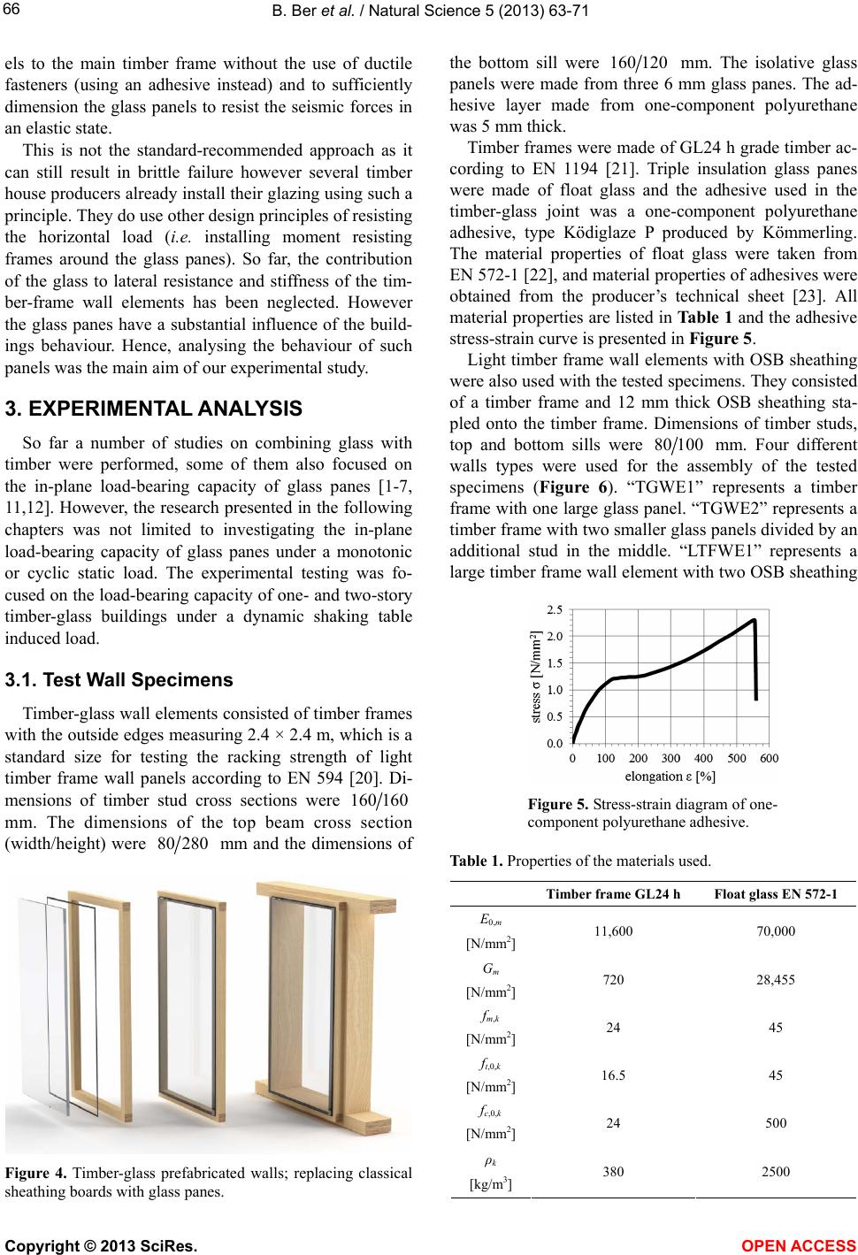
[23] F&E Kömmerling Chemische Fabrik GmbH (2011) Stress-
elongation-curve for Ködiglaze P/Ködiglaze P hv. Ger-
many (Stress-strain diagram—Figure 5 on page 4).
Copyright © 2013 SciRes. OPEN ACCESS