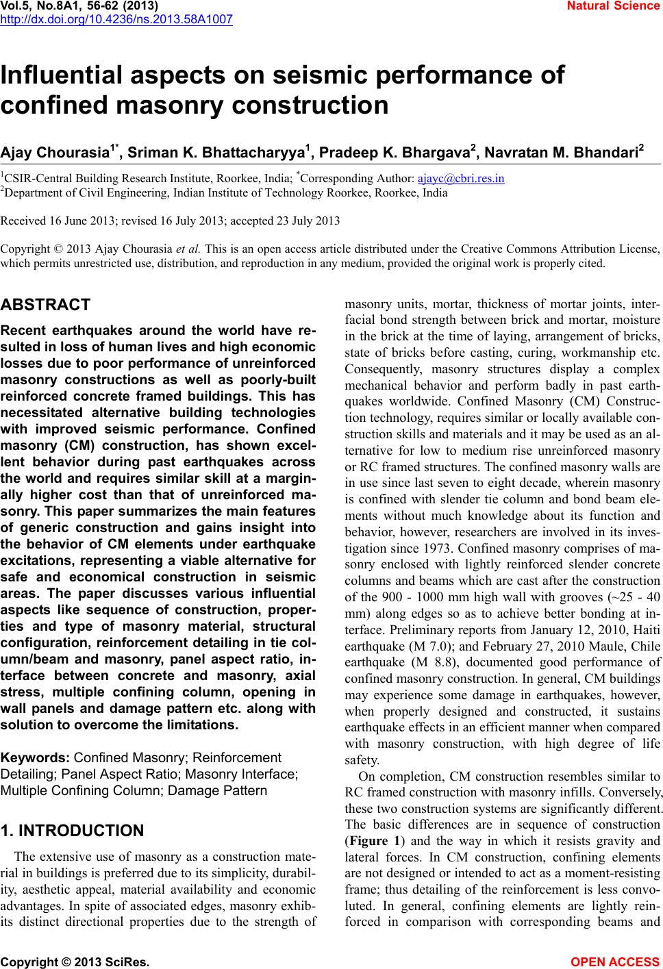
 Vol.5, No.8A1, 56-62 (2013) Natural Science http://dx.doi.org/10.4236/ns.2013.58A1007 Influential aspects on seismic performance of confined masonry construction Ajay Chourasia1*, Sriman K. Bhattacharyya1, Pradeep K. Bhargava2, Navratan M. Bhandari2 1CSIR-Central Building Research Institute, Roorkee, India; *Corresponding Author: ajayc@cbri.res.in 2Department of Civil Engineering, Indian Institute of Technology Roorkee, Roorkee, India Received 16 June 2013; revised 16 July 2013; accepted 23 July 2013 Copyright © 2013 Ajay Chourasia et al. This is an open access article distributed under the Creative Commons Attribution License, which permits unrestricted use, distribution, and reproduction in any medium, provided the original work is properly cited. ABSTRACT Recent earthquakes around the world have re- sulted in loss of human lives and high economic losses due to poor performance of unreinforced masonry constructions as well as poorly-built reinforced concrete framed buildings. This has necessitated alternative building technologies with improved seismic performance. Confined masonry (CM) construction, has shown excel- lent behavior during past earthquakes across the world and requires similar skill at a margin- ally higher cost than that of unreinforced ma- sonry. This paper summarizes the main features of generic construction and gains insight into the behavior of CM elements under earthquake excitations, representing a viable alternative for safe and economical construction in seismic areas. The paper discusses various influential aspects like sequence of construction, proper- ties and type of masonry material, structural configuration, reinforcement detailing in tie col- umn/beam and masonry, panel aspect ratio, in- terface between concrete and masonry, axial stress, multiple confining column, opening in wall panels and damage pattern etc. along with solution to overcome the limitations. Keywords: Confined Masonry; Reinforcement Detailing; Panel Aspect Ratio; Masonry Interface; Multiple Confining Column; Damage Pattern 1. INTRODUCTION The extensive use of masonry as a construction mate- rial in buildings is preferred due to its simplicity, du rabil- ity, aesthetic appeal, material availability and economic advantages. In spite of associated edges, masonry exhib- its distinct directional properties due to the strength of masonry units, mortar, thickness of mortar joints, inter- facial bond strength between brick and mortar, moisture in the brick at the time of laying, arrangement of bricks, state of bricks before casting, curing, workmanship etc. Consequently, masonry structures display a complex mechanical behavior and perform badly in past earth- quakes worldwide. Confined Masonry (CM) Construc- tion technology, requires similar or locally available con- struction skills and materials and it may be used as an al- ternative for low to medium rise unreinforced masonry or RC fra med stru ct ure s. Th e conf ined mas o nr y wa lls ar e in use since last seven to eight decade, wherein masonry is confined with slender tie column and bond beam ele- ments without much knowledge about its function and behavior, however, researchers are involved in its inves- tigation since 1973. Confined masonry comprises of ma- sonry enclosed with lightly reinforced slender concrete columns and beams which are cast after the construction of the 900 - 1000 mm high wall with grooves (~25 - 40 mm) along edges so as to achieve better bonding at in- terface. Preliminary reports from January 12, 2010, Haiti earthquake (M 7.0); and February 27, 2010 Maule, Chile earthquake (M 8.8), documented good performance of confined masonry construction. In general, CM buildings may experience some damage in earthquakes, however, when properly designed and constructed, it sustains earthquake effects in an efficient manner when compared with masonry construction, with high degree of life safety. On completion, CM construction resembles similar to RC framed construction with masonry infills. Conversely, these two construction systems are significantly different. The basic differences are in sequence of construction (Figure 1) and the way in which it resists gravity and lateral forces. In CM construction, confining elements are not designed or intended to act as a moment-resisting frame; thus detailing of the reinforcement is less convo- luted. In general, confining elements are lightly rein- forced in comparison with corresponding beams and Copyright © 2013 SciRes. OPEN ACC ESS 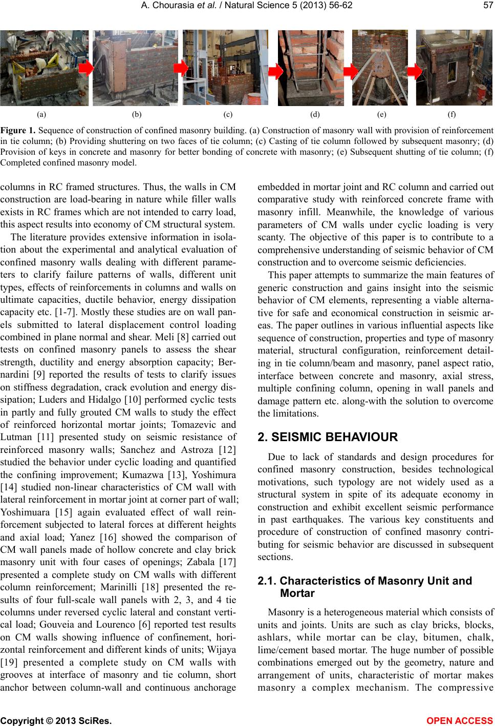 A. Chourasia et al. / Natural Science 5 (2013) 56-62 57 (a) (b) (c) (d) (e) (f) Figure 1. Sequence of construction of confined masonry building. (a) Construction of masonry wall with provision of reinforcement in tie column; (b) Providing shuttering on two faces of tie column; (c) Casting of tie column followed by subsequent masonry; (d) Provision of keys in concrete and masonry for better bonding of concrete with masonry; (e) Subsequent shutting of tie column; (f) Completed confined masonry model. columns in RC framed structures. Thus, the walls in CM construction are load-bearing in nature while filler walls exists in RC frames which are not intend ed to carry load, this aspect results into economy of CM structural system. The literature provides extensive information in isola- tion about the experimental and analytical evaluation of confined masonry walls dealing with different parame- ters to clarify failure patterns of walls, different unit types, effects of reinforcements in columns and walls on ultimate capacities, ductile behavior, energy dissipation capacity etc. [1-7]. Mostly these studies are on wall pan- els submitted to lateral displacement control loading combined in plane normal and shear. Meli [8] carried out tests on confined masonry panels to assess the shear strength, ductility and energy absorption capacity; Ber- nardini [9] reported the results of tests to clarify issues on stiffness degradation, crack evolution and energy dis- sipation; Luders and Hidalgo [10] performed cyclic tests in partly and fully grouted CM walls to study the effect of reinforced horizontal mortar joints; Tomazevic and Lutman [11] presented study on seismic resistance of reinforced masonry walls; Sanchez and Astroza [12] studied the behavior under cyclic loading and quantified the confining improvement; Kumazwa [13], Yoshimura [14] studied non-linear characteristics of CM wall with lateral reinforcement in mortar joint at corner part of wall; Yoshimuara [15] again evaluated effect of wall rein- forcement subjected to lateral forces at different heights and axial load; Yanez [16] showed the comparison of CM wall panels made of hollow concrete and clay brick masonry unit with four cases of openings; Zabala [17] presented a complete study on CM walls with different column reinforcement; Marinilli [18] presented the re- sults of four full-scale wall panels with 2, 3, and 4 tie columns under reversed cyclic lateral and constant verti- cal load; Gouveia and Lourenco [6] reported test results on CM walls showing influence of confinement, hori- zontal reinforcement and different kinds of units; Wijaya [19] presented a complete study on CM walls with grooves at interface of masonry and tie column, short anchor between column-wall and continuous anchorage embedded in mortar joint and RC column and carried out comparative study with reinforced concrete frame with masonry infill. Meanwhile, the knowledge of various parameters of CM walls under cyclic loading is very scanty. The objective of this paper is to contribute to a comprehensive understanding of seismic behavior of CM construction and to overcome seismic deficiencies. This paper attempts to summarize the main features of generic construction and gains insight into the seismic behavior of CM elements, representing a viable alterna- tive for safe and economical construction in seismic ar- eas. The paper outlines in various influential asp ects like sequence of constru ction, properties and type of masonry material, structural configuration, reinforcement detail- ing in tie column/beam and masonry, panel aspect ratio, interface between concrete and masonry, axial stress, multiple confining column, opening in wall panels and damage pattern etc. along-with the solution to overcome the limitations. 2. SEISMIC BEHAVIOUR Due to lack of standards and design procedures for confined masonry construction, besides technological motivations, such typology are not widely used as a structural system in spite of its adequate economy in construction and exhibit excellent seismic performance in past earthquakes. The various key constituents and procedure of construction of confined masonry contri- buting for seismic behavior are discussed in subsequent sections. 2.1. Characteristics of Masonry Unit and Mortar Masonry is a heterogeneous material which consists of units and joints. Units are such as clay bricks, blocks, ashlars, while mortar can be clay, bitumen, chalk, lime/cement based mortar. The huge number of possible combinations emerged out by the geometry, nature and arrangement of units, characteristic of mortar makes masonry a complex mechanism. The compressive Copyright © 2013 SciRes. OPEN AC CESS 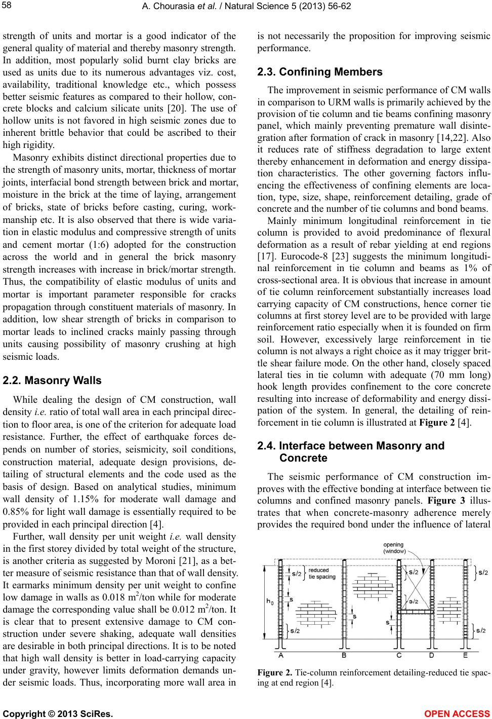 A. Chourasia et al. / Natural Science 5 (2013) 56-62 58 strength of units and mortar is a good indicator of the general quality of material and thereby masonry strength. In addition, most popularly solid burnt clay bricks are used as units due to its numerous advantages viz. cost, availability, traditional knowledge etc., which possess better seismic features as compared to their hollow, con- crete blocks and calcium silicate units [20]. The use of hollow units is not favored in high seismic zones due to inherent brittle behavior that could be ascribed to their high rigidi t y. Masonry exhibits distinct directional properties due to the strength of masonry units, mortar, thickness of mortar joints, interfacial bond strength between brick and mortar, moisture in the brick at the time of laying, arrangement of bricks, state of bricks before casting, curing, work- manship etc. It is also observed that there is wide varia- tion in elastic modulus and compressive strength of units and cement mortar (1:6) adopted for the construction across the world and in general the brick masonry strength increases with increase in brick/mortar strength. Thus, the compatibility of elastic modulus of units and mortar is important parameter responsible for cracks propagation through constituent materials of masonry. In addition, low shear strength of bricks in comparison to mortar leads to inclined cracks mainly passing through units causing possibility of masonry crushing at high seismic loads. 2.2. Masonry Walls While dealing the design of CM construction, wall density i.e. ratio of total wall area in each princip al d irec- tion to floor area, is one of the criterion for adequate load resistance. Further, the effect of earthquake forces de- pends on number of stories, seismicity, soil conditions, construction material, adequate design provisions, de- tailing of structural elements and the code used as the basis of design. Based on analytical studies, minimum wall density of 1.15% for moderate wall damage and 0.85% for light wall damage is essentially required to be provided in each principal direction [4] . Further, wall density per unit weight i.e. wall density in the first storey divided by total weigh t of the structure, is another criteria as suggested by Moroni [21], as a bet- ter measure of seismic resistance than that of wall density. It earmarks minimum density per unit weight to confine low damage in walls as 0.018 m2/ton wh ile for moderate damage the corresponding value shall be 0.012 m2/ton. It is clear that to present extensive damage to CM con- struction under severe shaking, adequate wall densities are desirable in both principal directions. It is to be noted that high wall density is better in load-carrying capacity under gravity, however limits deformation demands un- der seismic loads. Thus, incorporating more wall area in is not necessarily the proposition for improving seismic performance. 2.3. Confining Members The improvement in seismic performance of CM walls in comparison to URM walls is primarily achieved by the provision of tie column and tie beams confining masonry panel, which mainly preventing premature wall disinte- gration after formation of crack in masonry [14,22]. Also it reduces rate of stiffness degradation to large extent thereby enhancement in deformation and energy dissipa- tion characteristics. The other governing factors influ- encing the effectiveness of confining elements are loca- tion, type, size, shape, reinforcement detailing, grade of concrete and the number of tie columns and bond beams. Mainly minimum longitudinal reinforcement in tie column is provided to avoid predominance of flexural deformation as a result of rebar yielding at end regions [17]. Eurocode-8 [23] suggests the minimum longitudi- nal reinforcement in tie column and beams as 1% of cross-sectional area. It is obvious that increase in amount of tie column reinforcement substantially increases load carrying capacity of CM constructions, hence corner tie columns at first storey level are to b e provided with large reinforcement ratio especially when it is founded on firm soil. However, excessively large reinforcement in tie column is not always a right choice as it may trigger brit- tle shear failure mode. On the other hand, closely spaced lateral ties in tie column with adequate (70 mm long) hook length provides confinement to the core concrete resulting into increase of deformability and energy dissi- pation of the system. In general, the detailing of rein- forcement in tie column is illustrated at Figure 2 [4]. 2.4. Interface between Masonry and Concrete The seismic performance of CM construction im- proves with the effective bonding at interface between tie columns and confined masonry panels. Figure 3 illus- trates that when concrete-masonry adherence merely provides the required bond under the influence of lateral Figure 2. Tie-column reinforcement detailing-reduced tie spac- ing at end region [4]. Copyright © 2013 SciRes. OPEN AC CESS  A. Chourasia et al. / Natural Science 5 (2013) 56-62 59 Figure 3. Separation of masonry-concrete element at interface [14]. loads and occurrence of vertical separation and partial disintegration of the panel and confining elements at large deformations, which adversely affect the seismic performance of CM walls [14]. To overcome above problem, casting concrete against toothed (~25 - 40 mm or 1.5 times the average size of course aggregate in concrete) at masonry and concrete interface can be provided which act as shear keys. Alter- natively, providing the CM wall with connection rebar (U-shape or L-shape rebar that are anchored adequately into walls) helps to improve the bond and load trans- fer/deformation capacity [24]. Experimental tests per- formed on CM model by the authors demonstrates the formation of 0.5 mm wide crack at toothed interface be- tween tie column and masonry at a very later stage of formation of cracks in masonry panel (Figure 4). The interface effectiveness can also be enhanced by provision of 6 mm dia (450 mm long) reinforcement as dowel ade- quately embedded in tie column concrete and masonry mortar at every 5th course . 2.5. Aspect Ratio Aspect ratio of masonry panel (height to length) is one of the governing factors from damage pattern and failure mode consideration of CM walls. Squat CM walls with aspect ratios around one are commonly used in practice and its seismic behavior is mostly governed by shear deformations [25]. Nevertheless, as the aspect ratio in- creases, the flexural deformations become more domi- nant, leading to early crack formation and higher stiff- ness degradation, thereby affecting strength characteris- tics of the panel. For slender CM walls, flexural defor- mations greatly outdo those of shear, and, therefore, these walls are likely to fail in flexural mode. As a con- sequence, squat CM walls possess lower deformability as compared to its counterpart. While this aspect is of paramount importance, it has been overlooked in many codes and regulations that address seismic behavior of CM walls [26]. 2.6. Openings Size A typical masonry wall when subjected to earthquake Figure 4. Effectiveness of toothed interface between tie column and masonry. load, usually initiate shear cracks at the corners of open- ings and extends towards the middle of piers. Further, crushing of masonry units at corners is also a common phenomenon at higher loads. Thus, size, shape, location and confinement detailing of openings have a great im- pact on the seismic performance. The stiffness of walls with an opening ratio around 11% of total wall area is close to that of the specimen without openings [16]. 2.7. Horizontal Reinforcement in Masonry The provision of horizontal reinforcement in masonry panel influences the uniform distribution of cracks and improves shear resistance, deformation capacity, and energy dissipation characteristics of CM walls (Figure 5). Moreover, the rate at which stiffness and strength de- grade will substantially decline, and therefore, more sta- ble response curves are achieved, even at large deforma- tion levels. The ratio between horizontal reinforcement in ma- sonry panel to longitudinal reinforcement of tie column should be dealt judiciously so as to avoid the high possi- bility of flexural failure mode in case of over-reinforced walls [17]. As a result of provision of horizontal rein- forcement in masonry, delayed emergence of inclined cracks and spreading of shear cracks at the toe of wall were also noticed during various tests. When there is insufficient reinforcement at first-storey panels, fracture of rebar occurs near inclined cracks and in the mid part of the wall resulting into sliding of upper walls over the cracks [3]. The test results advocate horizontal reinforcement ra- tio in wall between 0.005 - 0.017, with an optimum value Copyright © 2013 SciRes. OPEN AC CESS 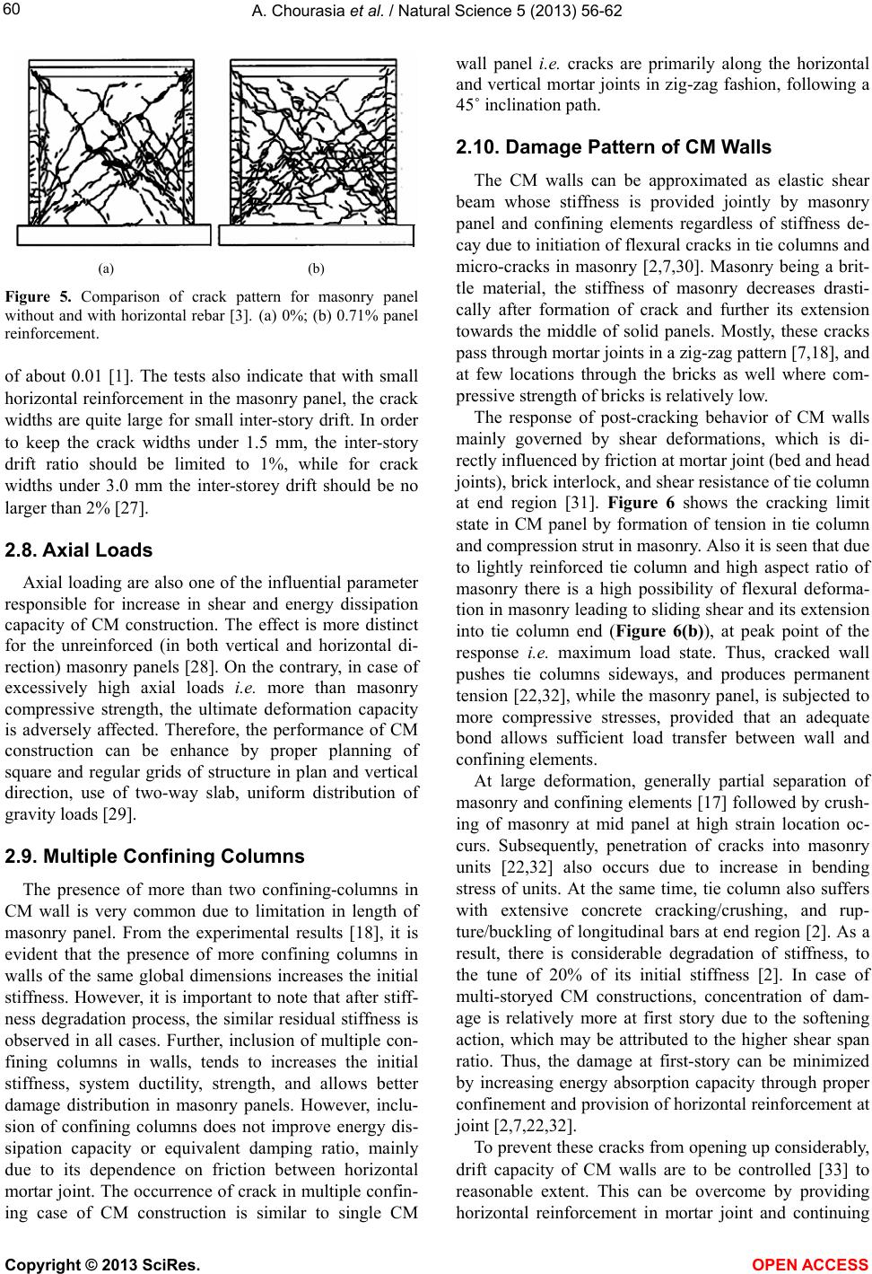 A. Chourasia et al. / Natural Science 5 (2013) 56-62 60 (a) (b) Figure 5. Comparison of crack pattern for masonry panel without and with horizontal rebar [3]. (a) 0%; (b) 0.71% panel reinforcement. of about 0.01 [1]. The tests also indicate that with small horizontal reinforcement in the masonry panel, the crack widths are quite large for small inter-story drift. In order to keep the crack widths under 1.5 mm, the inter-story drift ratio should be limited to 1%, while for crack widths under 3.0 mm the inter-storey drift should be no larger than 2% [27]. 2.8. Axial Loads Axial loading are also one of the influential parameter responsible for increase in shear and energy dissipation capacity of CM construction. The effect is more distinct for the unreinforced (in both vertical and horizontal di- rection) masonry panels [28]. On the contrary, in case of excessively high axial loads i.e. more than masonry compressive strength, the ultimate deformation capacity is adversely affected. Therefore, the performance of CM construction can be enhance by proper planning of square and regular grids of structure in plan and vertical direction, use of two-way slab, uniform distribution of gravity loads [29]. 2.9. Multiple Confining Columns The presence of more than two confining-columns in CM wall is very common due to limitation in length of masonry panel. From the experimental results [18], it is evident that the presence of more confining columns in walls of the same global dimensions increases the initial stiffness. However, it is important to note that after stiff- ness degradation process, the similar residual stiffness is observed in all cases. Further, inclusion of multiple con- fining columns in walls, tends to increases the initial stiffness, system ductility, strength, and allows better damage distribution in masonry panels. However, inclu- sion of confining columns does not improve energy dis- sipation capacity or equivalent damping ratio, mainly due to its dependence on friction between horizontal mortar joint. The o ccurrence of crack in multiple conf in- ing case of CM construction is similar to single CM wall panel i.e. cracks are primarily along the horizontal and vertical mortar joints in zig-zag fashion, following a 45˚ inclination path. 2.10. Damage Pattern of CM Walls The CM walls can be approximated as elastic shear beam whose stiffness is provided jointly by masonry panel and confining elements regardless of stiffness de- cay due to initiation of flexural cracks in tie columns and micro-cracks in masonry [2,7,30]. Masonry being a brit- tle material, the stiffness of masonry decreases drasti- cally after formation of crack and further its extension towards the middle of solid panels. Mostly, these cracks pass through mortar joints in a zig-zag pattern [7,18], and at few locations through the bricks as well where com- pressive strength of bricks is relatively low. The response of post-cracking behavior of CM walls mainly governed by shear deformations, which is di- rectly influenced by friction at mortar joint (bed and head joints), brick interlock, and shear resistance of tie column at end region [31]. Figure 6 shows the cracking limit state in CM panel by formation of tension in tie column and compression strut in masonry. Also it is seen that due to lightly reinforced tie column and high aspect ratio of masonry there is a high possibility of flexural deforma- tion in masonry leading to sliding shear and its exten sion into tie column end (Figure 6(b)), at peak point of the response i.e. maximum load state. Thus, cracked wall pushes tie columns sideways, and produces permanent tension [22,32], while the masonry panel, is subjected to more compressive stresses, provided that an adequate bond allows sufficient load transfer between wall and confining elements. At large deformation, generally partial separation of masonry and confining elements [17] followed by crush- ing of masonry at mid panel at high strain location oc- curs. Subsequently, penetration of cracks into masonry units [22,32] also occurs due to increase in bending stress of units. At the same time, tie column also suffers with extensive concrete cracking/crushing, and rup- ture/buckling of longitudinal bars at end region [2]. As a result, there is considerable degradation of stiffness, to the tune of 20% of its initial stiffness [2]. In case of multi-storyed CM constructions, concentration of dam- age is relatively more at first story due to the softening action, which may be attributed to the higher shear span ratio. Thus, the damage at first-story can be minimized by increasing energy absorption capacity through proper confinement and prov ision of horizontal reinfo rcement at joint [2,7,22,32]. To prevent these cracks from opening up considerably, drift capacity of CM walls are to be controlled [33] to reasonable extent. This can be overcome by providing horizontal reinforcement in mortar joint and continuing Copyright © 2013 SciRes. OPEN AC CESS 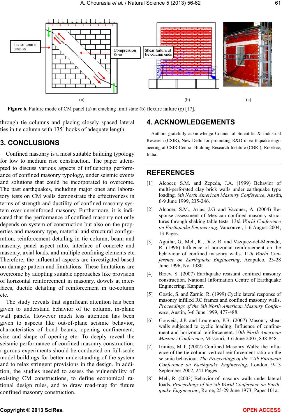 A. Chourasia et al. / Natural Science 5 (2013) 56-62 Copyright © 2013 SciRes. 61 (a) (b) (c) Figure 6. Failure mode of CM panel (a) at cracking limit state (b) flexure failure (c) [17]. 4. ACKNOWLEDGEMENTS through tie columns and placing closely spaced lateral ties in tie column with 135˚ hooks of adequate length. Authors gratefully acknowledge Council of Scientific & Industrial Research (CSIR), New Delhi for promoting R&D in earthquake engi- neering at CSIR-Central Building Research Institute (CBRI), Roorkee, India. 3. CONCLUSIONS Confined masonry is a most su itable build ing typolog y for low to medium rise construction. The paper attem- pted to discuss various aspects of influencing perform- ance of confined masonry typology, under seismic events and solutions that could be incorporated to overcome. The past earthquakes, including major ones and labora- tory tests on CM walls demonstrate the effectiveness in terms of strength and ductility of confined masonry sys- tem over unreinforced masonry. Furthermore, it is indi- cated that the performance of confined masonry not only depends on system of construction but also on the prop- erties and masonry type, material and structural configu- ration, reinforcement detailing in tie column, beam and masonry, panel aspect ratio, interface of concrete and masonry, axial loads, and multiple con f ining elements etc. Therefore, the influential aspects are investigated based on damage pattern and limitations. These limitations are overcome by adopting suitable approaches like provision of horizontal reinforcement in masonry, dowels at inter- faces, ductile detailing of reinforcement in tie-column etc. REFERENCES [1] Alcocer, S.M. and Zepeda, J.A. (1999) Behavior of multi-perforated clay brick walls under earthquake type loading. 8th North American Masonry Conference, Austin, 6-9 June 1999, 235-246. [2] Alcocer, S.M., Arias, J.G. and Vazquez, A. (2004) Re- sponse assessment of Mexican confined masonry struc- tures through shaking table tests. 13th World Conference on Earthquake Engineering, Va ncouver, 1-6 August 2004, 13 Pages. [3] Aguilar, G., Meli, R., Diaz, R. and Vazquez-del-Mercado, R. (1996) Influence of horizontal reinforcement on the behaviour of confined masonry walls. 11th World Con- ference on Earthquake Engineering, Acapulco, 23-28 June 1996, No. 1380. [4] Brzev, S. (2007) Earthquake resistant confined masonry construction. National Information Centre of Earthquake Engineering, Kanpur. [5] Gostic, S. and Zarnic, R. (1999) Cyclic lateral response of masonry infilled RC frames and confined masonry walls. Proceedings of the 8th North American Masonry Confer- ence, Austin, 3-6 June 1999, 477-488. The study reveals that significant attention has been given to understand behavior of tie column, in-plane wall panels. However much less attention has been given to aspects like out-of-plane seismic behavior, characteristics of bond beams, opening confinement, size and shape of opening etc. To deeply reveal the seismic performance of confined masonry construction, rigorous experiments should be conducted on full-scale model buildings for better understanding of the system and to relax stringent provisions in the design. In addi- tion, the studies needed to assess the vulnerability of existing CM constructions, to define economical ra- tional design rules, and to draw road-map for future confined masonry construction. [6] Gouveia, J.P. and Lourenco, P.B. (2007) Masonry shear walls subjected to cyclic loading: Influence of confine- ment and horizontal reinforcement. 10th North American Masonry Conference, Missouri, 3-6 June 2007, 838-848. [7] Irimies, M.T. (2002) Confined Masonry Walls: the influ- ence of the tie-column vertical reinforcement ratio on the seismic behaviour. The Proceedings of the 12th European Conference on Earthquake Engineering, London, 9-13 September 2002, 241 Pages. [8] Meli, R. (2003) Behavior of masonry walls under lateral loads. Proceedings of the 5th World Conference on Earth- quake Engineering, Rome, 25-29 June 1973, Paper 101a. OPEN A CCESS  A. Chourasia et al. / Natural Science 5 (2013) 56-62 62 [9] Bernardini, A., Modena, C., Turnesek, V. and Vescovi, U. (1980) A comparison of three laboratory tests. [10] Luders, C. and Hidalgo, P. (1986) Ïnfluencia dei refuerzo horizontal en el comportamiento seismico de muros de albanileria armada. Cuartas Jornadas Chilenas de Sis- mologia e Ingenieria Antisismica, 2, H139-H158. [11] Tomazevic, M. and Lutman, M. (1988) Seismic resistance of reinforced masonry walls. Proceedings of the 9th World Conference on Earthquake Engineering, Japan As, for Earthquake Disaster Prevention, Tokyo, 2-9 August 1988, VI/97-102. [12] Sanchez, T.A., Flores, L.E., Leon F., Alcocer S.M. and Meli, R. (1992) Respuesta sismica de muros de mampos- teria confinada con diferentes grados de acoplamiento a flexion. CENAPRED, Informe ES/02/91, 106 Pages. [13] Kumazava, F. and Ohkubo, M. (2000) Nonlinear charac- teristics of confined masonry wall with lateral reinforce- ment in mortar joints. Proceedings of the 12th World Conference on Earthquake Engineering, Auckland, Paper No. 743. [14] Yoshimura, K., Kikuchi, K., Kuroki, M., Nonaka, H., Kim, K.T., Matsumoto, Y., et al. (2003) Experimental study on reinforcing methods for confined masonry walls subjected to seismic forces. 9th North American Masonry Conference, Clemson, 1-4 June 2003, 89-100. [15] Yoshimura, K., Kikuchi, K., Kuroki, M., Liu, L. and Ma, L. (2000) Effect of wall reinforcement, applied lateral forces and vertical axial loads on seismic behavior of confined concrete masonry walls. 12th World Conference on Earthquake Engineering, Paper No. 0984. [16] Yanez, F., Astroza, M., Holmberg, A. and Ogaz, O. (2004) Behavior of confined masonry shear walls with large openings. 13th World Conference on Earthquake Engi- neering, Vancouver, 1-6 August 2004, Paper No. 3438. [17] Zabala. C., Honma, C., Gibu, P., Gallardo, P. and Huaco, G. (2004) Full scale on line test on two story masonry building using handmade bricks. 13th World Conference on Earthquake Engineering, Vancouver, 1-6 August 2004, 14 Pages. [18] Marinilli, A. and Castilla, E. (2004) Experimental evalua- tion of confined masonry walls with several confin- ing-columns. 13th World Conference on Earthquake En- gineering, Vancouver, 1-6 August 2004, 12 Pages. [19] Wijaya, W., Kusumastuti, D., Suarjana, M., Rildova and Pribadi, K. (2011) Experimental study on wall-frame con- nection of confined masonry wall. Procedia Engineering, 14, 2094-2102. doi:10.1016/j.proeng.2011.07.263 [20] Alcocer, S.M., Arias, J.G. and Vazquez, A. (2003) The New Mexico City building code requirements for design and construction of masonry structures. The Proceedings of the 9th North American Masonry Conference, Clemson, 1-4 June 2003, 656-667. [21] Moroni, M., Astroza M. and Caballero, R. (2000) Wall density and seismic performance of confined masonry buildings. TMS Journal, 18, 81-88. [22] Tomazevic, M. and Klemenc, I. (1997) Seismic behaviour of confined masonry walls. Earthquake Engineering and Structural Dynamics, 26, 1059-1071. doi:10.1002/(SICI)1096-9845(199710)26:10<1059::AID- EQE694>3.0.CO;2-M [23] European committee for standardization (2002) European standard. [24] Arya, A.S. (2000) Non-engineered construction in de- veloping countries—An approach toward earthquake risk reduction. Proceedings of the 12th World Conference on Earthquake Engineering, 33, 187-208. [25] Alvarez, J.J. (1996) Some topics on the seismic behaviour of confined masonry structures. 11th World Conference on Earthquake Engineering, Acapulco, Paper No. 180. [26] Meli R., Svetlana Brzev, et al. (2011) Seismic design guide for low rise confined masonry buildings. EERI & IAEE, T okyo. [27] Moroni, M., Astroza M. and Mesias, P. (1996) Displace- ment capacity and required story drift in confined ma- sonry buildings. 11th World Conference on Earthquake Engineering, Acapulco, Paper No. 1059. [28] Ishibashi, K., Meli, R., Alcocer, S.M., Leon, F. and San- chez, T.A. (1992) Experimental study on earthquake-re- sistant design of confined masonry structures. Proceed- ings of the 10th World Conference on Earthquake Engi- neering, Madrid, 19-24 July 1992, 3469-3474. [29] Bariola, J. and Delgado, C. (1996) Design of confined masonry walls under lateral loading. 11th World Confer- ence on Earthquake Engineering, Acapulco, Paper No. 204. [30] Gibu, P. and Zavala C. (2002) The current state-of-the-art of masonry and adobe building in Peru. Japan Peru Cen- ter for Earthquake Engineering Research and Disaster Mitigation, Lima. [31] Flores, L.E. and Alcocer, S.M. (1996) Calculated re- sponse of confined masonry structures. 11th World Con- ference on Earthquake Engineering, Acapulco, Paper No. 1830. [32] Tomazevic, M. and Klemenc, I. (1997) Verification of seismic resistance of confined masonry buildings. Earth- quake Engineering and Structural Dynamics, 26, 1073- 1088. doi:10.1002/(SICI)1096-9845(199710)26:10<1073::AID- EQE695>3.0.CO;2-Z [33] Alcocer, S.M. (1996) Implications derived from recent research in Mexico on confined masonry structures. Worldwide Advances in Structural Concrete and Masonry: Proceedings of the CCMS Symposium Held in Conjunc- tion with Structures Congress XIV, Chicago, 15-18 April 1996, 82-92. Copyright © 2013 SciRes. OPEN AC CESS
|