X. Y. SU, Q. F. XU 13
3.2. The Selection of Magneto-Optical Crystal
Since the Verdet constant varies with the dynamic tem-
perature, the temperature coefficient should be consid-
ered during the selection of magneto-optical crystal.
When the te mperatu re change s from -2 5℃ to +80℃, the
Verdet constant of FR-5, a paramagnetic material, is re-
duced by 30% throughout the mutative temperature and
YIG that is a ferromagnetic material has 25% irregular
variation, while ZF-7 that is an anti-magnetic material
only changes 0.79% [3]. Similarly, an anti-magnetic ma-
terial called MR1 almost has no effect on the Verdet
constant in the temperature ranging from -55 to +135℃.
Additionally, its Verdet constant is as high as 0.065 -
0.092 min/Oe.cm (@ 632.8 nm) which is helpful to
shorten the crystal length and reduce the line birefrin-
gence. Therefore, the MR1 is employed in this design.
As the OCT using light to measure the magnetic field
surrounding a current carrying conductor has a transfer
function with a sine wave characteristics which made the
OCT polarization interference be a non-linear portion.
An approximate linear relationship between sin2θ and 2θ
introduced in the section 2 can fix th is problem when θ is
small enough. Ultimately, the OCT accuracy level will
determine the maximum Faraday deflection angle and the
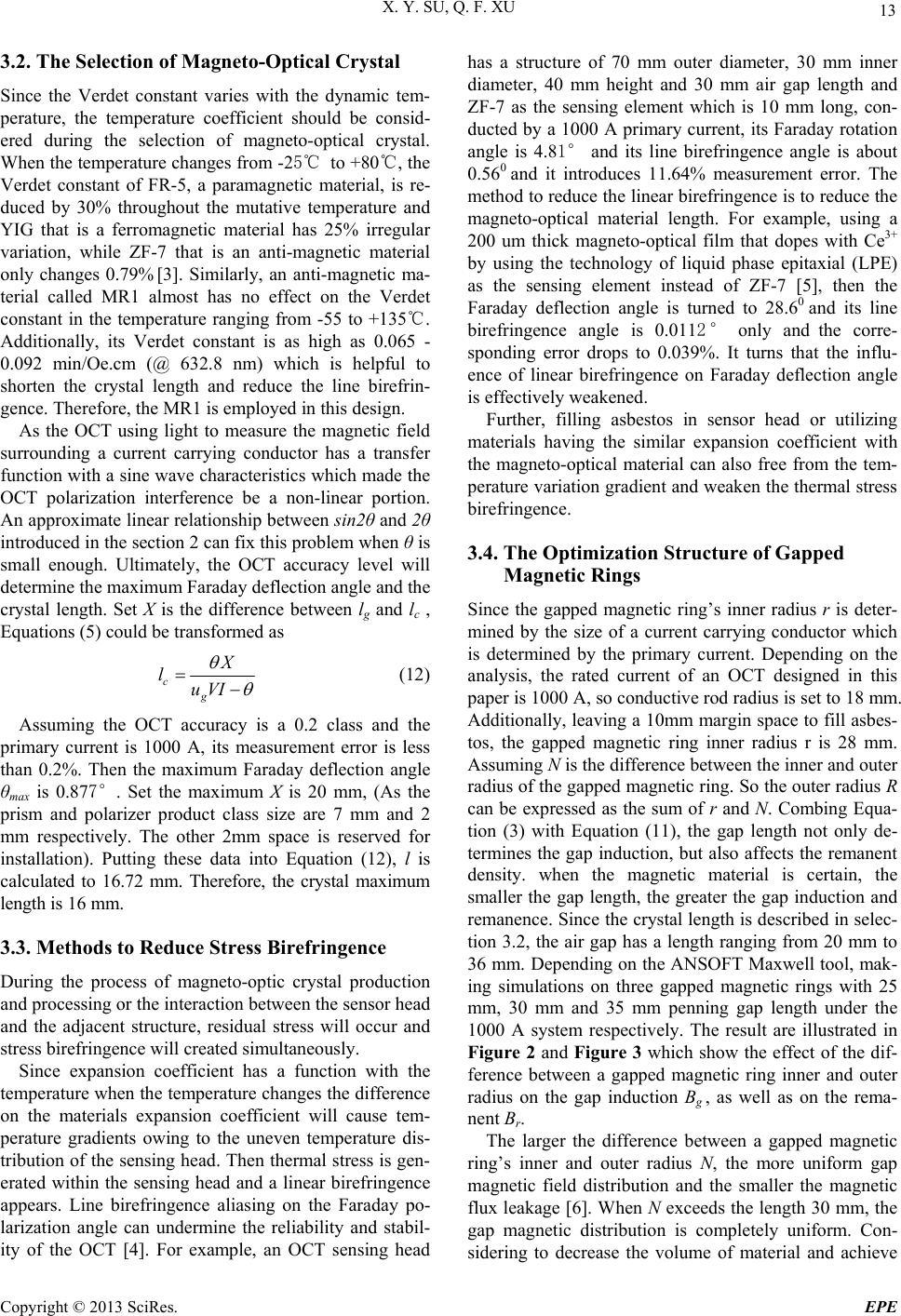
crystal length. Set X is the difference between lg and lc ,
Equations (5) could be transformed as
c
X
l
g
uV
I
(12)
Assuming the OCT accuracy
pr
Reduce Stress Birefringence
tion
ilar expansion coefficient with
th
mization Structure of Gapped
Magnetic Rings
eter-
mineurrent carrying conductor which
ner and outer radius N, the more uniform gap
m
is a 0.2 class and the
imary current is 1000 A, its measurement error is less
than 0.2%. Then the maximum Faraday deflection angle
θmax is 0.877°. Set the maximum X is 20 mm, (As the
prism and polarizer product class size are 7 mm and 2
mm respectively. The other 2mm space is reserved for
installation). Putting these data into Equation (12), l is
calculated to 16.72 mm. Therefore, the crystal maximum
length is 16 mm.
3.3. Methods to
During the process of magneto-optic crystal produc
and processing or the in teract ion between the sensor head
and the adjacent structure, residual stress will occur and
stress birefringence will created simultaneously.
Since expansion coefficient has a function with the
temperature when the temperature ch anges the di fferenc e
on the materials expansion coefficient will cause tem-
perature gradients owing to the uneven temperature dis-
tribution of the sens ing head. Then thermal stress is gen-
erated within the sensing head and a linear birefringence
appears. Line birefringence aliasing on the Faraday po-
larization angle can undermine the reliability and stabil-
ity of the OCT [4]. For example, an OCT sensing head
has a structure of 70 mm outer diameter, 30 mm inner
diameter, 40 mm height and 30 mm air gap length and
ZF-7 as the sensing element which is 10 mm long, con-
ducted by a 1000 A primary current, its Faraday rotation
angle is 4.81° and its line birefringence angle is about
0.560 and it introduces 11.64% measurement error. The
method to reduce the linear birefring ence is to reduce the
magneto-optical material length. For example, using a
200 um thick magneto-optical film that dopes with Ce3+
by using the technology of liquid phase epitaxial (LPE)
as the sensing element instead of ZF-7 [5], then the
Faraday deflection angle is turned to 28.60 and its line
birefringence angle is 0.0112° only and the corre-
sponding error drops to 0.039%. It turns that the influ-
ence of linear birefringence on Faraday deflection angle
is effectively weakened.
Further, filling asbestos in sensor head or utilizing
materials having the sim
e magneto-optical material can also free from the tem-
perature variation gradient and weaken the thermal stress
birefringence.
3.4. The Opti
Since the gapped magnetic ring’s inner radius r is d
d by the size of a c
is determined by the primary current. Depending on the
analysis, the rated current of an OCT designed in this
paper is 1000 A, so conductive rod radius is set to 18 mm.
Additionally, leaving a 10mm margin sp ace to fill asbes-
tos, the gapped magnetic ring inner radius r is 28 mm.
Assuming N is the difference between th e inne r and ou ter
radius of the gapped magnetic ring. So the outer radius R
can be expressed as the sum of r and N. Combing Equa-
tion (3) with Equation (11), the gap length not only de-
termines the gap induction, but also affects the remanent
density. when the magnetic material is certain, the
smaller the gap length, the greater the gap induction and
remanence. Since the crystal length is described in selec-
tion 3.2, the air gap has a length ranging from 20 mm to
36 mm. Depending on the ANSOFT Maxwell tool, mak-
ing simulations on three gapped magnetic rings with 25
mm, 30 mm and 35 mm penning gap length under the
1000 A system respectively. The result are illustrated in
Figure 2 and Figure 3 which show the effect of the dif-
ference between a gapped magnetic ring inner and outer
radius on the gap induction Bg , as well as on the rema-
nent Br.
The larger the difference between a gapped magnetic
ring’s in
agnetic field distribution and the smaller the magnetic
flux leakage [6]. When N exceeds the length 30 mm, the
gap magnetic distribution is completely uniform. Con-
sidering to decrease the volume of material and achieve
Copyright © 2013 SciRes. EPE