 Energy and Power Engineering, 2013, 5, 6-10 doi:10.4236/epe.2013.53B002 Published Online May 2013 (http://www.scirp.org/journal/epe) The Pitch Control Algorithm of Wind Turbine Based on Fuzzy Control and PID Control Rui Guo, Jinsong Du, Jinghui Wu, Yiyang Liu Wind Power Control Technology Department, Shenyang Institute of Automation Chinese Academy of Sciences, Shenyang, China Email: guorui@sia.cn Received 2013 ABSTRACT Due to the special features of great inertia, pure lag and non-lin earity provided with wind turbine, coupled with complex and variable working co nd ition, it is d ifficult to achiev e satis facto ry con tro l results simply b y employin g trad itio nal PID, which has the drawbacks such as adjustment inconvenience, poor anti-interference, and large overshoot, and prolonged adjust span. This paper puts forward one type of improved controller combining Fuzzy Con trol with PID Control. W ith larger speed deviation, the controller emphasizes Fuzzy Control to speed system response; with less speed deviation, the controller emphasizes PID Control to improve control accuracy. Simulation Test directing at the algorithm is based on the Bladed software, with the positive result of improved dynamic and static performance of wind turbine under large disturbance. Keywords: Fuzzy Control; Pitch Control; Wind Turbine; Bladed 1. Introduction In general, most current wind turbines, asynchronous doubly-fed or synchr onous, adopt pitch contro l system to ensure safe operation of wind turbines above the rated wind speed and output steady rated power [1]. Pitch con- trol system is considered to have two modes, Hydraulic and Electric pitch-controlled system. No matter driven by any of the two modes, the overall pitch co ntrol system is regarded as actuating element in the generator revolving closed-loop control system, implementing pitch angle signal transmitted by the main control system. That is to say wind turbine alters wind-power utilization coefficien t by means of changing pitch angle to maintain stable output power [2]. At present pitch controller is simple PID control. Though receiving wide application in indus- try field, PID control, confined by non-linearity charac- teristic of wind turbine, makes it difficult to adjust pa- rameters, which leads to untimely restraint of instability caused by external disturbance. The above-mentioned difficulty accordingly brings about a series of problems such as unstable revolving speed, reduced generating efficiency, and quickened wear process, etc. Although some scholars bring forward the theory of applying multi groups of PID parameters on the basis of pitch angle to ensure rapidity and stability of pitch process, it is diffi- cult to tune multi groups of parameters on site [3]. Intelligent control is based upon Control Theory, In- formation Theory, Artificial Intelligence, Bionics, Neu- rophysiology and Computer Science, and gradually de- velops to advanced information and control technology. Fuzzy Control is one kind of Intelligent Control. It doesn’t need accuracy dynamic model, but uses artificial control rule to organize control decision table, then comes up wit h outputs. The paper proposes one type of pitch control algorithm of wind turbine based on Fuzzy Control and PID Control, with flexible and adaptable advantages of Fuzzy Control and accurate characteristic of PID Control. It helps to work out traditional pitch control algorithm, conduct on simulation test platform, and achieves desirable control results. 2. Asynchronous Doubly-fed Wind Turbine Pitch Control Strategy There are two types of Asynchronous doubly-fed wind turbine pitch control strategy based on different rotor speed: above or below rated wind speed area. In the area below the rated wind speed, the wind tur- bine is designed to capture wind energy as much as pos- sible, and usually with lower aerodynamic load com- pared with above rated wind speed area. So the main control system doesn’t issue an order to the p itch control system, i.e. the wind turbines run at fixed pitch. When it is above the rated wind speed, the rotor speed has reached the rated speed area or above. Pitch system should be effective in adjusting wind turbines to absorb Copyright © 2013 SciRes. EPE 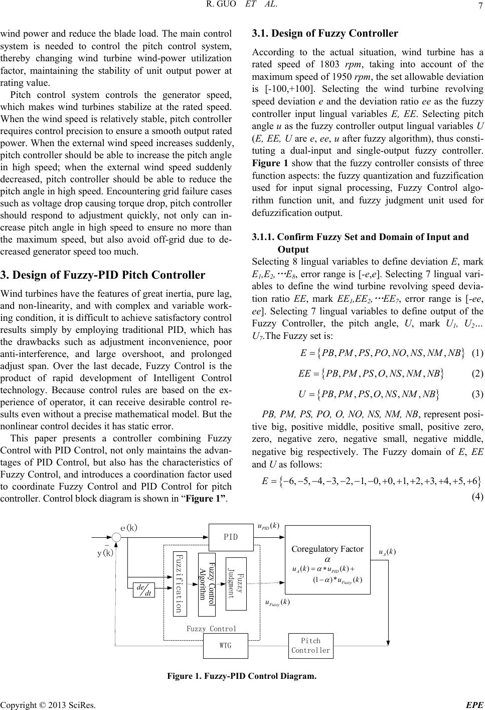 R. GUO ET AL. 7 wind power and reduce the blade load. The main control system is needed to control the pitch control system, thereby changing wind turbine wind-power utilization factor, maintaining the stability of unit output power at rating value. Pitch control system controls the generator speed, which makes wind turbines stabilize at the rated speed. When the wind speed is relatively stable, p itch controller requires control precision to ensure a smooth output rated power. When the external wind speed increases suddenly, pitch controller shou ld be able to increase the p itch angle in high speed; when the external wind speed suddenly decreased, pitch controller should be able to reduce the pitch angle in high speed. Encountering grid failure cases such as voltage drop causing torque drop, pitch controller should respond to adjustment quickly, not only can in- crease pitch angle in high speed to ensure no more than the maximum speed, but also avoid off-grid due to de- creased generator speed too much. 3. Design of Fuzzy-PID Pitch Controller Wind turbines have the features of great inertia, pure lag, and non-linearity, and with complex and variable work- ing condition, it is difficult to achieve satisfactor y control results simply by employing traditional PID, which has the drawbacks such as adjustment inconvenience, poor anti-interference, and large overshoot, and prolonged adjust span. Over the last decade, Fuzzy Control is the product of rapid development of Intelligent Control technology. Because control rules are based on the ex- perience of operator, it can receive desirable control re- sults even without a precise mathe matical model. But the nonlinear control decides it has static error. This paper presents a controller combining Fuzzy Control with PID Control, not only maintains the advan- tages of PID Control, but also has the characteristics of Fuzzy Control, and introduces a coordination factor used to coordinate Fuzzy Control and PID Control for pitch controller. Control block di agram is shown i n “ Figure 1”. 3.1. Design of Fuzzy Controller According to the actual situation, wind turbine has a rated speed of 1803 rpm, taking into account of the maximum speed of 1950 rpm, the set allowable deviation is [-100,+100]. Selecting the wind turbine revolving speed deviation e and the deviation ratio ee as the fuzzy controller input lingual variables E, EE. Selecting pitch angle u as the fuzzy controller outpu t lingual variables U (E, EE, U are e, ee, u after fuzzy alg orithm), thus consti- tuting a dual-input and single-output fuzzy controller. Figure 1 show that the fuzzy controller consists of three function aspects: the fuzzy quantization and fuzzification used for input signal processing, Fuzzy Control algo- rithm function unit, and fuzzy judgment unit used for defuzzification output. 3.1.1. C on f irm Fuzzy Set and Domain of Input and Output Selecting 8 lingual variables to define deviation E, mark E1,E2, … E8, error range is [-e,e]. Selecting 7 lingual vari- ables to define the wind turbine revolving speed devia- tion ratio EE, mark EE1,EE2, … EE7, error range is [-ee, ee]. Selecting 7 lingual variables to define output of the Fuzzy Controller, the pitch angle, U, mark U1, U2… U7.The Fuzzy set is: ,,,,,,,EPBPMPSPONONSNMNB (1) ,,,,,,EEPB PMPS O NSNMNB (2) ,,,,,,UPB PMPSO NSNMNB (3) PB, PM, PS, PO, O, NO, NS, NM, NB, represent posi- tive big, positive middle, positive small, positive zero, zero, negative zero, negative small, negative middle, negative big respectively. The Fuzzy domain of E, EE and U as follows: 6, 5, 4, 3,2, 1, 0, 0, 1, 2, 3, 4, 5, 6E (4) () PID uk () Fuzzy uk () A uk () () APID uku k (1) *() Fuzzy uk dedt Figure 1. Fuzzy-PID Control Diagram. Copyright © 2013 SciRes. EPE  R. GUO ET AL. 8 6, 5, 4, 3, 2, 1,0, 1, 2, 3, 4, 5, 6EE (5) 6, 5, 4, 3, 2, 1,0, 1, 2, 3, 4, 5, 6U (6) The membership is shown in “Tables 1-3”. 3.1.2. Conclude the Control Rules Based on the actual work conditions and expertise, after tests again and again, the fuzzy control rules are con- firmed as is shown in “Table 4”. When the error is nega- tive, and the error ratio is also negative, the error is in an increasing trend. Selecting PB or PM control amount is to remove the existing erro rs. When the error is neg ative, and the error ratio is positive, the error is in reducing Table 1. Membership assignment of E. Table 2. Membership assignment of EE. Table 3. Membership assignment of U. Table 4. Fuzzy control rules. EC E NB NMNS O PS PMPB NB PB PB PB PB PM PS O NM PB PB PB PM PS O O NS PB PB PMPS O NS NS NO PMPS PS O NS NMNM PO PMPMPS O NS NS NM PS PS PS O NS NM NB NB PM O O NS NM NB NB NB PB O NS NM NB NB NB NB trend. It is necessary to take smaller control amount to eliminate the error as soon as possible and prevent the occurrence of overshoot. When the error is positive, and the error ratio is negative, the error is in the decreasing trend. It is advisable to take smaller control amount. When the error is positiv e, and the error ratio is positive, the error is in increasing trend, selecting the PB or PM. Computer language presentation of the above rules are: if E=NB and EE=NB then, U=PB (7) if E=NB and EE=NM then, U=PB (8) if E=NB and EE=NS then, U=PB (9) if E=NB and EE=O then, U=PB (10) The control rules can be concluded as follows: From formula 7 can achieve such fuzzy expression: 1 T EE U RNBNB PB (11) In the same way, the fuzzy relation of 1256 can be obtained. From the above 56 Fuzzy relation ma- trix can reach to total Fu zzy relation matrix. ,RRR 56 1i i R R (12) Formula 12 represents the overall control decision fuzzy relation matrix, including controller input and out- put relation. With the relation, the fuzzy amount of out- put U can get from E, EE. UUE EER (13) The Assignment is shown in “Table 5”. 3.1.3. De fuzzification Applying the maximum membership principle to the output value defuzzification processing in fuzzy control table. Selecting the maximum element U* o f me mb er s hi p functio n as t he final outp ut value, u(k)=U*. Copyright © 2013 SciRes. EPE 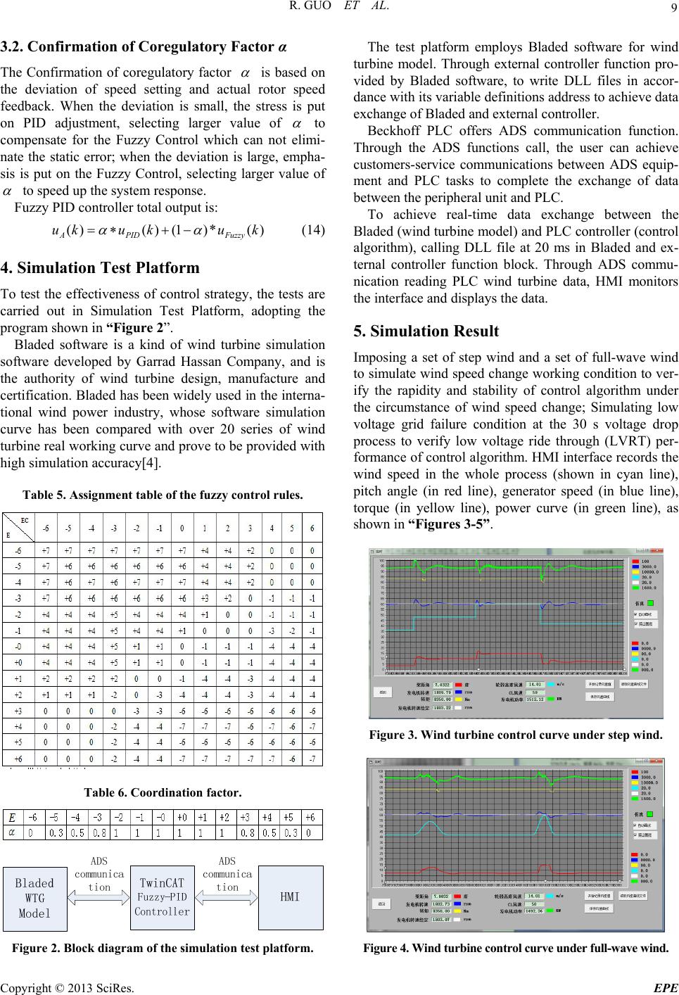 R. GUO ET AL. 9 3.2. Confirmation of Coregulatory Factor α The Confirmation of coregulatory factor is based on the deviation of speed setting and actual rotor speed feedback. When the deviation is small, the stress is put on PID adjustment, selecting larger value of to compensate for the Fuzzy Control which can not elimi- nate the static error; when the deviation is large, empha- sis is put on the Fuzzy Control, selecting larger value of to speed up the system response. Fuzzy PID controller total output is: ()() (1)*() A PIDFuzzy uku kuk (14) 4. Simulation Test Platform To test the effectiveness of control strategy, the tests are carried out in Simulation Test Platform, adopting the program shown in “Figure 2”. Bladed software is a kind of wind turbine simulation software developed by Garrad Hassan Company, and is the authority of wind turbine design, manufacture and certification. Bladed has been widely used in the interna- tional wind power industry, whose software simulation curve has been compared with over 20 series of wind turbine real working curve and prove to be pr ovid ed with high simulation accuracy[4]. Table 5. Assignment table of the fuzzy control rules. Table 6. Coordination factor. Figure 2. Block diagram of the simulation test platform. The test platform employs Bladed software for wind turbine model. Through external controller function pro- vided by Bladed software, to write DLL files in accor- dance with its variable definitions address to achieve data exchange of Bladed and external controller. Beckhoff PLC offers ADS communication function. Through the ADS functions call, the user can achieve customers-service communications between ADS equip- ment and PLC tasks to complete the exchange of data between the peripheral unit and PLC. To achieve real-time data exchange between the Bladed (wind turbine model) and PLC controller (control algorithm), calling DLL file at 20 ms in Bladed and ex- ternal controller function block. Through ADS commu- nication reading PLC wind turbine data, HMI monitors the interface and displays the data. 5. Simulation Result Imposing a set of step wind and a set of full-wave wind to simulate wind speed change working condition to ver- ify the rapidity and stability of control algorithm under the circumstance of wind speed change; Simulating low voltage grid failure condition at the 30 s voltage drop process to verify low voltage ride through (LVRT) per- formance of control algorithm. HMI interface records the wind speed in the whole process (shown in cyan line), pitch angle (in red line), generator speed (in blue line), torque (in yellow line), power curve (in green line), as shown in “Figure s 3-5”. Figure 3. Wind turbine control curve under step wind. Figure 4. Wind turbine control curve under full-wave wind. Copyright © 2013 SciRes. EPE 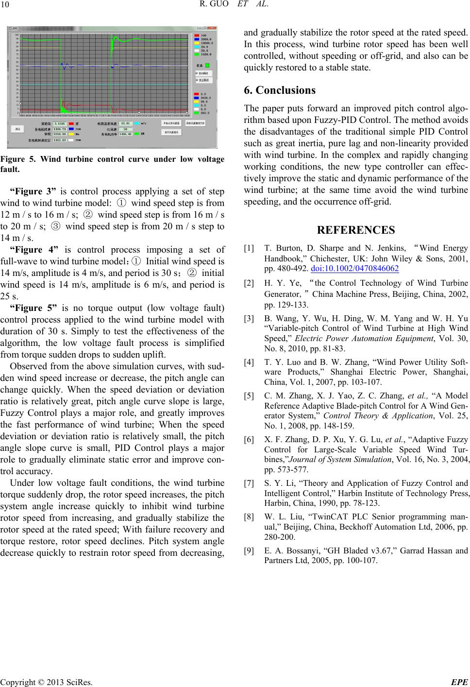 R. GUO ET AL. Copyright © 2013 SciRes. EPE 10 and gradually stabilize the rotor speed at the rated speed. In this process, wind turbine rotor speed has been well controlled, without speeding or off-grid, and also can be quickly restored to a stable state. 6. Conclusions The paper puts forward an improved pitch control algo- rithm based upon Fuzzy-PID Control. The method avoids the disadvantages of the traditional simple PID Control such as great inertia, pure lag and non-linearity provided with wind turbine. In the complex and rapidly changing working conditions, the new type controller can effec- tively improve the static and dynamic performance of the wind turbine; at the same time avoid the wind turbine speeding, and the occurrence off-grid. Figure 5. Wind turbine control curve under low voltage fault. “Figure 3” is control process applying a set of step wind to wind turbine model: ① wind speed step is from 12 m / s to 16 m / s; ② wind speed step is from 16 m / s to 20 m / s; ③ wind speed step is from 20 m / s step to 14 m / s. REFERENCES [1] T. Burton, D. Sharpe and N. Jenkins, “Wind Energy Handbook,” Chichester, UK: John Wiley & Sons, 2001, pp. 480-492. doi:10.1002/0470846062 “Figure 4” is control process imposing a set of full-wave to wind turbine model:① Initial wind speed is 14 m/s, amplitude is 4 m/s, and period is 30 s;② initial wind speed is 14 m/s, amplitude is 6 m/s, and period is 25 s. [2] H. Y. Ye, “the Control Technology of Wind Turbine Generator,”China Machine Press, Beijing, China, 2002, pp. 129-133. “Figure 5” is no torque output (low voltage fault) control process applied to the wind turbine model with duration of 30 s. Simply to test the effectiveness of the algorithm, the low voltage fault process is simplified from torque sudden drops to sudden uplift. [3] B. Wang, Y. Wu, H. Ding, W. M. Yang and W. H. Yu “Variable-pitch Control of Wind Turbine at High Wind Speed,” Electric Power Automation Equipment, Vol. 30, No. 8, 2010, pp. 81-83. [4] T. Y. Luo and B. W. Zhang, “Wind Power Utility Soft- ware Products,” Shanghai Electric Power, Shanghai, China, Vol. 1, 2007, pp. 103-107. Observed from the above simulation curves, with sud- den wind speed increase or decrease, the pitch angle can change quickly. When the speed deviation or deviation ratio is relatively great, pitch angle curve slope is large, Fuzzy Control plays a major role, and greatly improves the fast performance of wind turbine; When the speed deviation or deviation ratio is relatively small, the pitch angle slope curve is small, PID Control plays a major role to gradually eliminate static error and improve con- trol accuracy. [5] C. M. Zhang, X. J. Yao, Z. C. Zhang, et al., “A Model Reference Adaptive Blade-pitch Control for A Wind Gen- erator System,” Control Theory & Application, Vol. 25, No. 1, 2008, pp. 148-159. [6] X. F. Zhang, D. P. Xu, Y. G. Lu, et al., “Adaptive Fuzzy Control for Large-Scale Variable Speed Wind Tur- bines,”Journal of System Simulation, Vol. 16, No. 3, 2004, pp. 573-577. Under low voltage fault conditions, the wind turbine torqu e suddenly drop , the rotor sp eed incre ases, the p itch system angle increase quickly to inhibit wind turbine rotor speed from increasing, and gradually stabilize the rotor speed at the rated speed; With failure recovery and torque restore, rotor speed declines. Pitch system angle decrease quickly to restrain rotor speed from decreasing, [7] S. Y. Li, “Theory and Application of Fuzzy Control and Intelligent Control,” Harbin Institute of Technology Press, Harbin, China, 1990, pp. 78-123. [8] W. L. Liu, “TwinCAT PLC Senior programming man- ual,” Beijing, China, Beckhoff Automation Ltd, 2006, pp. 280-200. [9] E. A. Bossanyi, “GH Bladed v3.67,” Garrad Hassan and Partners Ltd, 2005, pp. 100-107.
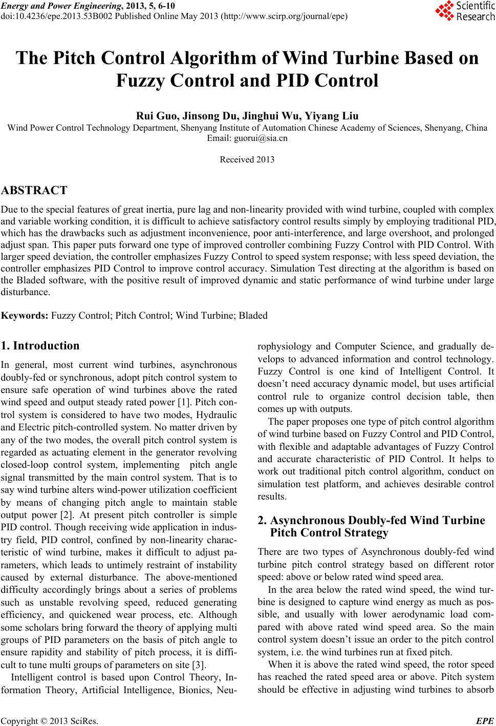
|