J. P. YUAN ET AL.
62
Prior to the laboratory test, it is important to predict
the various performance of these two ventilation systems
using the CFD technique. Airpak software was used to
simulate these two systems numerically and the com-
parison of performances of both ventilations will be re-
ported in both thermal comfort and indoor art quality
(IAQ) two aspects.
2. CFD Model and Boundary Conditions
2.1. Physical Model
The computational model was developed based on a
commercial program, the Chinese restaurant kitchen of
Clancy Hotel (kitchen) Equipment Corporation Ltd. And
the object of research is the operation room of the
kitchen. The kitchen model entity was simplified prop-
erly to establish the physical model for research. The
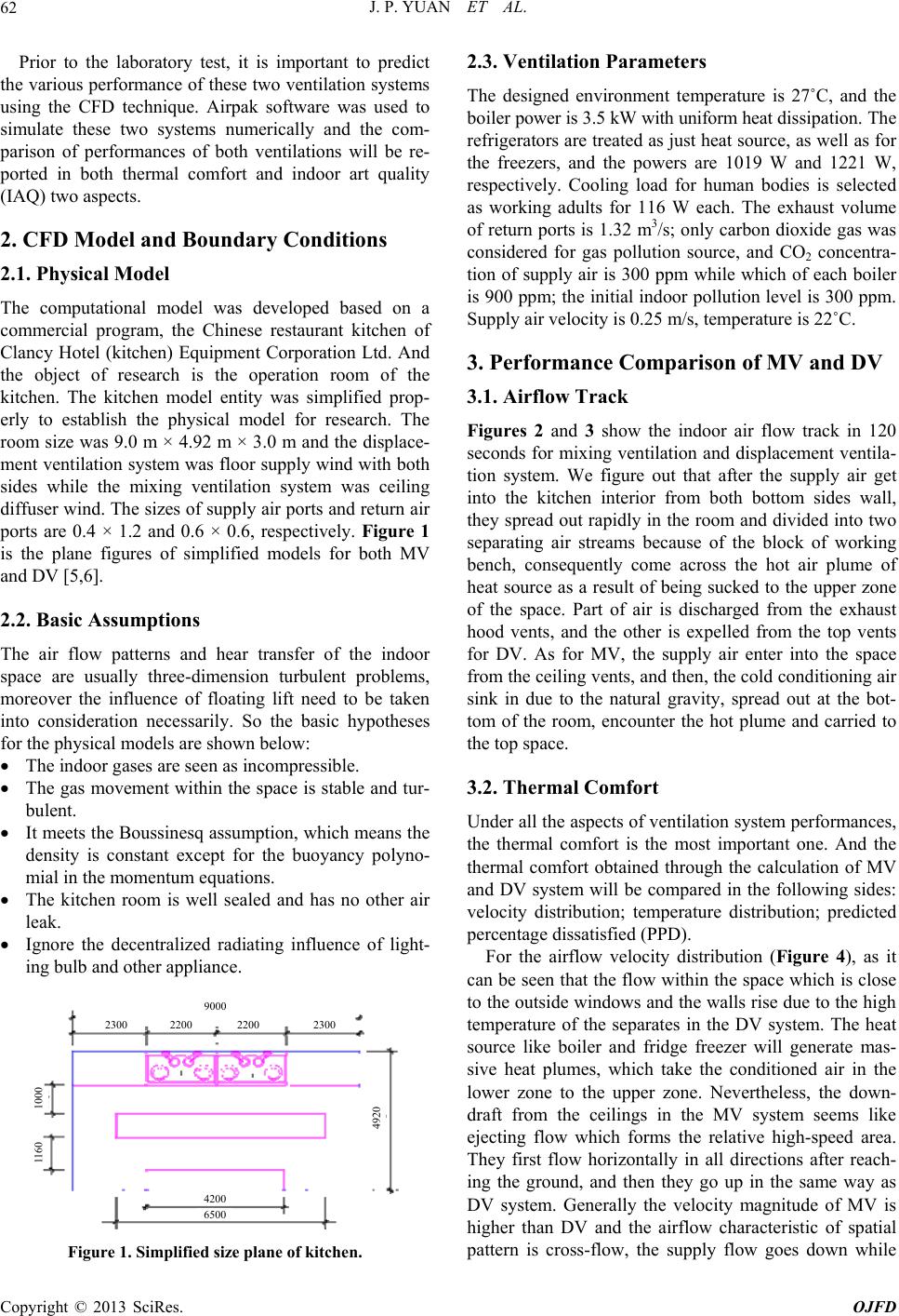
room size was 9.0 m × 4.92 m × 3.0 m and the displace-
ment ventilation system was floor supply wind with both
sides while the mixing ventilation system was ceiling
diffuser wind. The sizes of supply air ports an d return air
ports are 0.4 × 1.2 and 0.6 × 0.6, respectively. Figure 1
is the plane figures of simplified models for both MV
and DV [5,6].
2.2. Basic Assumptions
The air flow patterns and hear transfer of the indoor
space are usually three-dimension turbulent problems,
moreover the influence of floating lift need to be taken
into consideration necessarily. So the basic hypotheses
for the physical models are shown below:
The indoor gases are seen as incompressible.
The gas movement within the space is stable and tur-
bulent.
It meets the Boussinesq assumption, which means the
density is constant except for the buoyancy polyno-
mial in the momentum equations.
The kitchen room is well sealed and has no other air
leak.
Ignore the decentralized radiating influence of light-
ing bulb and other appl i ance.
9000
2200 2200 2300 2300
4200
6500
1160 1000
4920
Figure 1. Simplified size plane of kitchen.
2.3. Ventilation Parameters
The designed environment temperature is 27˚C, and the
boi le r power is 3.5 kW with uniform heat dissi p at io n . Th e
refrigerators are treated as just heat source, as well as for
the freezers, and the powers are 1019 W and 1221 W,
respectively. Cooling load for human bodies is selected
as working adults for 116 W each. The exhaust volume
of return ports is 1.32 m3/s; only carbon dioxide gas was
considered for gas pollution source, and CO2 concentra-
tion of supply air is 300 ppm while which of each boiler
is 900 ppm; the initial indoor pollution lev el is 300 ppm.
Supply air velocity is 0.25 m/s, temperature is 22˚C.
3. Performance Comparison of MV and DV
3.1. Airflow Track
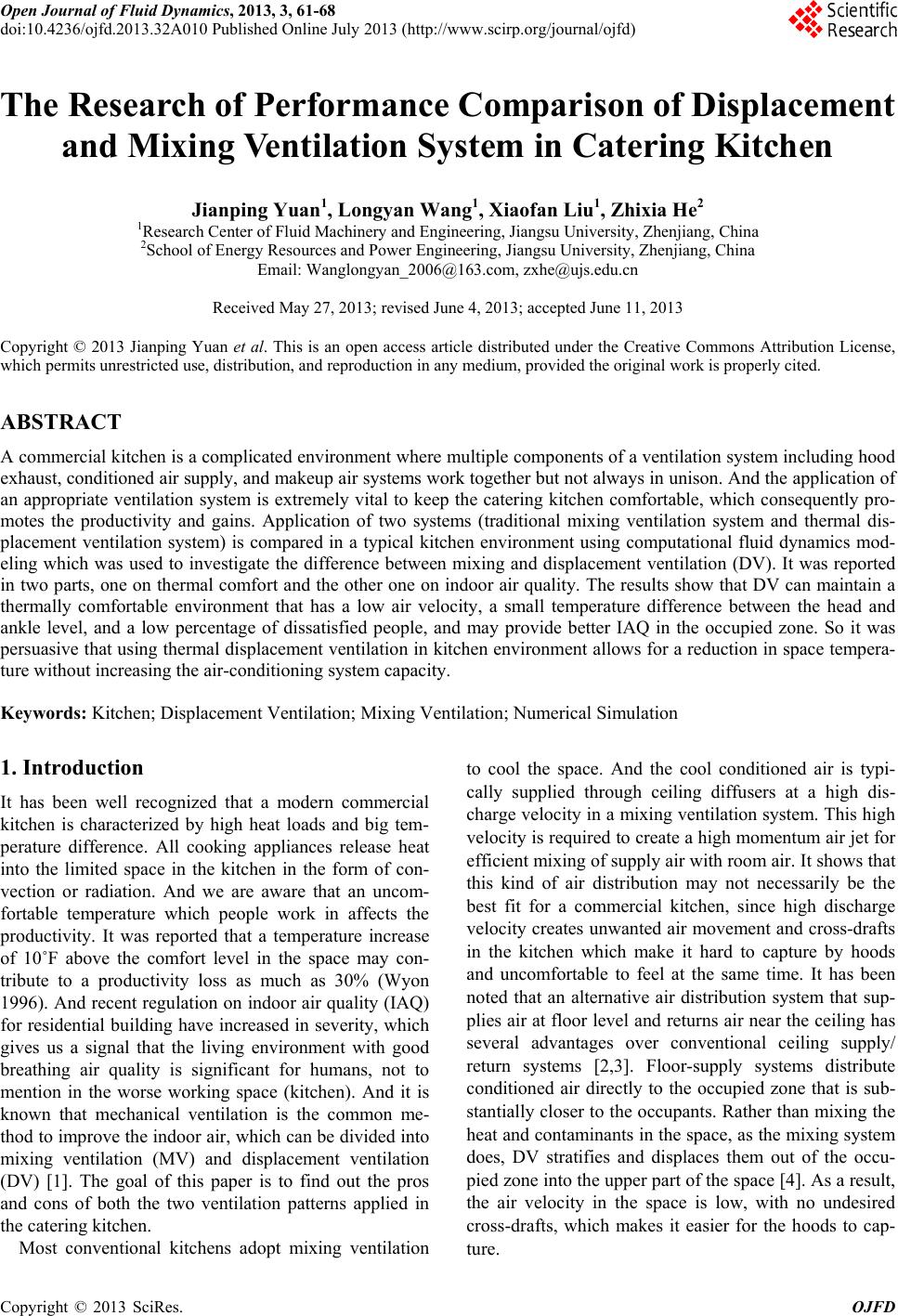
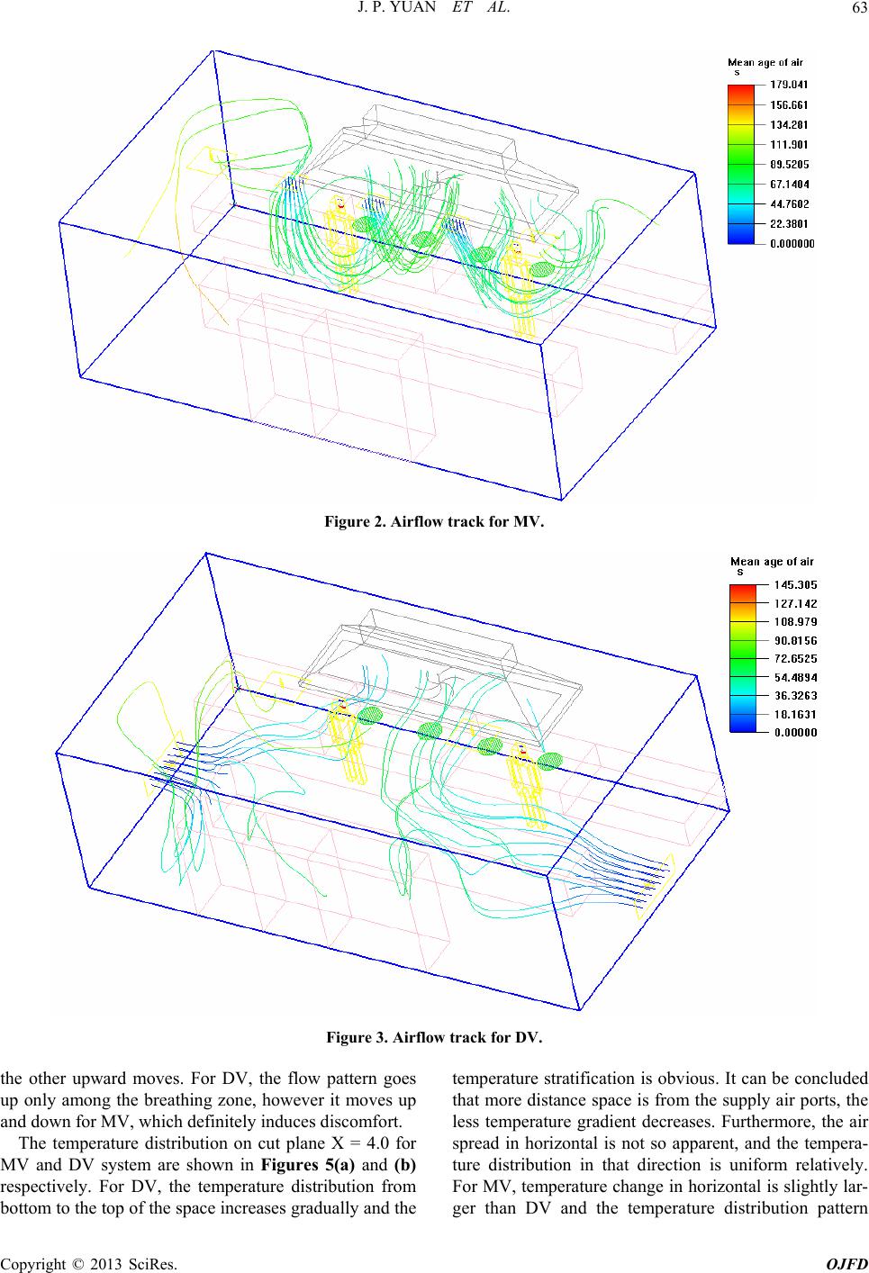
Figures 2 and 3 show the indoor air flow track in 120
seconds for mixing ventilation and displacement ventila-
tion system. We figure out that after the supply air get
into the kitchen interior from both bottom sides wall,
they spread out rapidly in the room and divided into two
separating air streams because of the block of working
bench, consequently come across the hot air plume of
heat source as a result of being sucked to the upper zone
of the space. Part of air is discharged from the exhaust
hood vents, and the other is expelled from the top vents
for DV. As for MV, the supply air enter into the space
from the ceiling vents, an d then, the co ld cond itioning air
sink in due to the natural gravity, spread out at the bot-
tom of the room, encounter the hot plume and carried to
the top space.
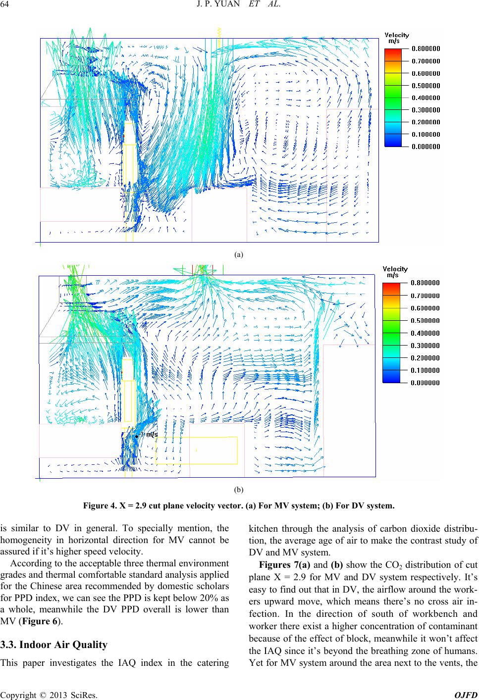
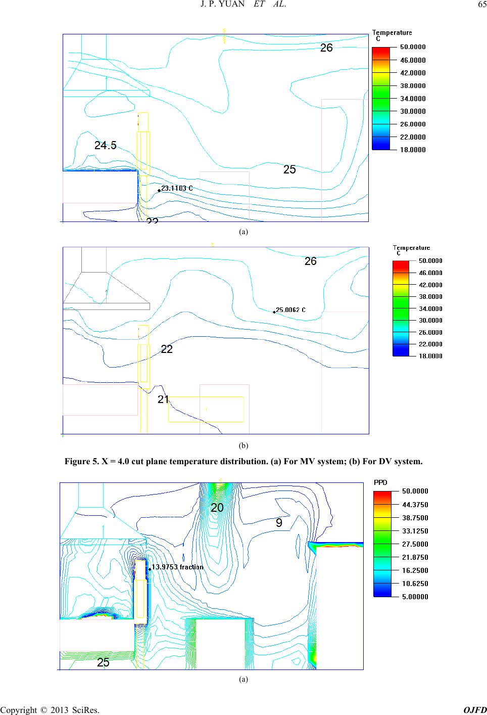
3.2. Thermal Comfort
Under all the aspects of ventilation system performances,
the thermal comfort is the most important one. And the
thermal comfort obtained through the calculation of MV
and DV system will be compared in the following sides:
velocity distribution; temperature distribution; predicted
percentage dissatisfied (PPD).
For the airflow velocity distribution (Figure 4), as it
can be seen that the flow within th e space which is close
to the outside windows and the walls rise due to the high
temperature of the separates in the DV system. The heat
source like boiler and fridge freezer will generate mas-
sive heat plumes, which take the conditioned air in the
lower zone to the upper zone. Nevertheless, the down-
draft from the ceilings in the MV system seems like
ejecting flow which forms the relative high-speed area.
They first flow horizontally in all directions after reach-
ing the ground, and then they go up in the same way as
DV system. Generally the velocity magnitude of MV is
higher than DV and the airflow characteristic of spatial
attern is cross-flow, the supply flow goes down while p
Copyright © 2013 SciRes. OJFD