International Journal of Clean Coal and Energy, 2013, 2, 16-20
doi:10.4236/ijcce.2013.22B004 Published Online May 2013 (http://www.scirp.org/journal/ijcce)
A Sun Tracking System Design for a Large Dish
Solar Concentrator
Xiaoshan Jin1*, Guoqiang Xu1, Rongjiu Zhou2, Xiang Luo1, Yongkai Quan1
1School of Energy & Power Engineering, Beihang University, Beijing, China
2Shouhang Resource Saving Company Limited, Beijing, China
Email: xiaoshan_jin@163.com, guoqiang_xu@buaa.edu.cn, 442759218@qq.com,
xiang.luo@buaa.edu.cn, quanyongkai@126.com
Received 2013
ABSTRACT
Energy crisis promotes the development of renewable energy, especially the solar energy. Sun tracking system proposed
in this paper is such a device for efficiency improvement. This closed loop tracking system with two axis sun tracking
method is controlled by a programmable logic controller (PLC) and is used for a large dish solar collector. A
combination tracking mode combined active and passive tracking methods used in the design make the tracker efficient
whatever the circumstances. Two stepper motors and two reduction boxes move the device towards the sun with chain
transmission. Besides sun tracking, the system also has functions of overheat monitoring, wind speed monitoring and
measurement of illumination.
Keywords: Renewable Energy; Solar Energy; Sun tracking; PLC; Combination Tracking Mode
1. Introduction
International energy structure adjustment and the energy
crisis promote the development of renewable energy.
Solar energy has gained much more focus because of its
endless and eco-friendly features. In 2012, the
International Energy Agency(IEA) point out in its report
“World energy outlook 2012” [1] that renewable energy
has become an integral part of the global energy structure
and it will be the world’s second largest power source in
2015. In 2035, power generation of renewable energy
will account for about one-third of electricity output, and
the solar energy will be the fastest one among it.
Solar thermal power generation is one of the main
ways of solar energy utilization which has been widely
used throughout the world. The dish solar thermal power
generation usually uses a two axis sun tracker having
high tracking accuracy and thermoelectric conversion
efficiency. Thermal solar tracking needs higher tracking
precision compared with photovoltaic. Through
simulation of light incidence by TRACEPRO software,
the collector will lose half of total energy in 1.2 light
deflection and will lose all energy in 1. deflection.
While the value is 0.3, the light loss less than 5%.
Photovoltaic tracking losses only 1.5% in 10°deviation
of light.
This paper introduces a solar tracking system which
controlled by the programmable logic controller (PLC) to
improve solar energy efficiency. Active and passive
tracking control methods with a closed loop system could
accommodate different weather conditions. Two stepper
motors and two reduction boxes are used to control the
rotation of the collector with chain transmission. The
goal in this system is to achieve a tracking precision
within 0.. In this case, the light energy loss would be
negligible.
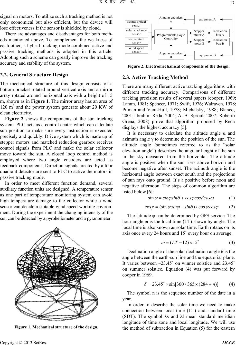
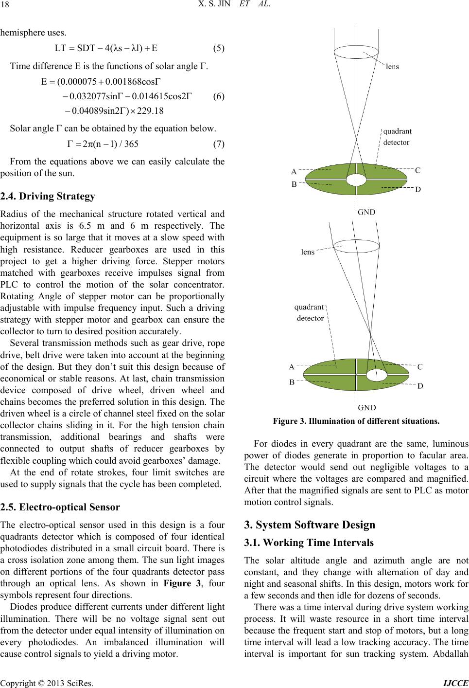
2. Sun Tracking System Design
2.1. Tracking Mode Selection
There is different automatic sun tracking methods
according to different solar concentrator. These methods
are usually sorted into three categories: active tracking
methods, passive tracking method and combination of
both[2-4].
Active tracking method can calculate the altitude angle
and azimuth of the sun by preset program in PLC. The
system can determine the position of the sun as long as
the latitude-longitude and date-time information has been
input. The upside to this method is that the system can’t
be affected by outside factors such as cloud and dust. The
downside is that this mode has a low tracking precision
while it has a high cost. So it is difficult to design such a
structure at the same time.
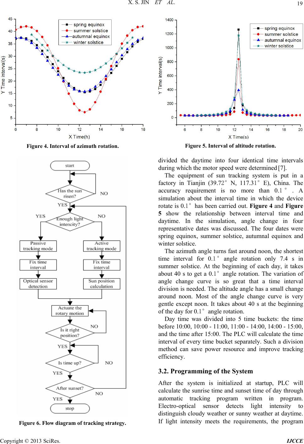
Passive tracking method is based on electoral-optical
sensors which can indicate the deflection of light.
Imbalance light make these sensors product control
Copyright © 2013 SciRes. IJCCE
X. S. JIN ET AL. 17
signal on motors. To utilize such a tracking method is not
only economical but also efficient, but the device will
lose effectiveness if the sensor is shielded by cloud.
There are advantages and disadvantages for both meth-
ods mentioned above. To complement the weakness of
each other, a hybrid tracking mode combined active and
passive tracking methods is adopted in this article.
Adopting such a scheme can greatly improve the tracking
accuracy and stability of the system.
2.2. General Structure Design
The mechanical structure of this design consists of a
bottom bracket rotated around vertical axis and a mirror
array rotated around horizontal axis with a height of 15
m, shown as in Figure 1. The mirror array has an area of
120 m2 and the power system generate about 20 KW of
clean electricity.
Figure 2 shows the components of the sun tracking
system. PLC acts as a control center which can calculate
sun position to make sure every instruction is executed
precisely and quickly. Drive system which is made up of
stepper motors and matched reduction gearbox receives
control signals from PLC and make the solar collector
move toward the sun. A closed loop control method is
employed where two angle encoders are acted as
feedback components. Direction signals created by a four
quadrant detector are sent to PLC to active the motors in
passive tracking mode.
In order to meet different function demand, several
auxiliary function units are designed. A temperature sensor
as one part of temperature monitoring system can avoid
high temperature damage to the collector while a wind
sensor can decide a suitable wind speed working environ-
ment. During the experiment the changing intensity of the
sun can be detected by a pyroheliometer and a pyranometer.
Figure 1. Mechanical structure of the design.
Figure 2. Electromechanical components of the design.
2.3. Active Tracking Method
There are many different active tracking algorithms with
different tracking accuracy. Comparisons of different
tracking precision results of several papers (cooper, 1969;
Lamm, 1981; Spencer, 1971; Swift, 1976; Walraven, 1978;
Pitman and Vant-Hull, 1978; Michalsky, 1988; Blanco,
2001; Ibrahim Reda, 2004; A. B. Sproul, 2007; Roberto
Grena, 2008) prove that algorithm proposed by Reda
displays the highest accuracy [5].
It is necessary to calculate the altitude angle α and
azimuth angle γ to determine the position of the sun. The
altitude angle (sometimes referred to as the “solar
elevation angle”) describes the angular height of the sun
in the sky measured from the horizontal. The altitude
angle is positive when the sun rises above horizon and
become negative after sunset. The azimuth angle is the
horizontal angle between exact south and the projections
of sun rays onto ground. It’s a positive before noon and
negative afternoon. The steps of common algorithm are
listed below [6]:
sin
s
insincos cos cos
 
(1)
s ico n(os)/cs
s
in sincos
 
(2)
The latitude φ can be determined by GPS service. The
hour angle ω is the local time (LT) shown by angle. The
local time is also known as solar time. Earth rotates on its
axis once every 24 hours and 15˚ every hour on average.
o
(12)1LT
5 (3)
Declination angle of the solar declination angle δ is the
angle between the earth-sun line and the equatorial plane.
It varies between –23.45˚ on winner solstice and 23.45˚
on summer solstice. Equation (4) was put forward by
cooper in 1969.
o
23.45sin[360 / 365(284)]n
  (4)
The symbol n is the sequence number of the date in a
year.
In order to describe the solar time we need to make
connection between local time (LT) and standard time
(SDT). The symbol λs and λl mean standard meridian
longitude of time zone and local longitude. We will use
the method of subtraction in Equation (5) for the eastern
Copyright © 2013 SciRes. IJCCE
X. S. JIN ET AL.
18
hemisphere uses.
λLsTSDT4( )E λl (5)
Time difference E is the functions of solar angle Γ.
(0.000075 0.001868cos
0.032077sin0.014615cos2
0.04089sin2)229.8
E
1
 


(6)
Solar angle Γ can be obtained by the equation below.
2π( n1)/365 (7)
From the equations above we can easily calculate the
position of the sun.
2.4. Driving Strategy
Radius of the mechanical structure rotated vertical and
horizontal axis is 6.5 m and 6 m respectively. The
equipment is so large that it moves at a slow speed with
high resistance. Reducer gearboxes are used in this
project to get a higher driving force. Stepper motors
matched with gearboxes receive impulses signal from
PLC to control the motion of the solar concentrator.
Rotating Angle of stepper motor can be proportionally
adjustable with impulse frequency input. Such a driving
strategy with stepper motor and gearbox can ensure the
collector to turn to desired position accurately.
Several transmission methods such as gear drive, rope
drive, belt drive were taken into account at the beginning
of the design. But they don’t suit this design because of
economical or stable reasons. At last, chain transmission
device composed of drive wheel, driven wheel and
chains becomes the preferred solution in this design. The
driven wheel is a circle of channel steel fixed on the solar
collector chains sliding in it. For the high tension chain
transmission, additional bearings and shafts were
connected to output shafts of reducer gearboxes by
flexible coupling which could avoid gearboxes’ damage.
At the end of rotate strokes, four limit switches are
used to supply signals that the cycle has been completed.
2.5. Electro-optical Sensor
The electro-optical sensor used in this design is a four
quadrants detector which is composed of four identical
photodiodes distributed in a small circuit board. There is
a cross isolation zone among them. The sun light images
on different portions of the four quadrants detector pass
through an optical lens. As shown in Figure 3, four
symbols represent four directions.
Diodes produce different currents under different light
illumination. There will be no voltage signal sent out
from the detector under equal intensity of illumination on
every photodiodes. An imbalanced illumination will
cause control signals to yield a driving motor.
Figure 3. Illumination of different situations.
For diodes in every quadrant are the same, luminous
power of diodes generate in proportion to facular area.
The detector would send out negligible voltages to a
circuit where the voltages are compared and magnified.
After that the magnified signals are sent to PLC as motor
motion control signals.
3. System Software Design
3.1. Working Time Intervals
The solar altitude angle and azimuth angle are not
constant, and they change with alternation of day and
night and seasonal shifts. In this design, motors work for
a few seconds and then idle for dozens of seconds.
There was a time interval during drive system working
process. It will waste resource in a short time interval
because the frequent start and stop of motors, but a long
time interval will lead a low tracking accuracy. The time
interval is important for sun tracking system. Abdallah
Copyright © 2013 SciRes. IJCCE
X. S. JIN ET AL.
Copyright © 2013 SciRes. IJCCE
19
Figure 5. Interval of altitude rotation.
Figure 4. Interval of azimuth rotation.
divided the daytime into four identical time intervals
during which the motor speed were determined [7].
The equipment of sun tracking system is put in a
factory in Tianjin (39.7N, 117.3E), China. The
accuracy requirement is no more than 0.. A
simulation about the interval time in which the device
rotate is 0.has been carried out. Figure 4 and Figure
5 show the relationship between interval time and
daytime. In the simulation, angle change in four
representative dates was discussed. The four dates were
spring equinox, summer solstice, autumnal equinox and
winter solstice.
The azimuth angle turns fast around noon, the shortest
time interval for 0.angle rotation only 7.4 s in
summer solstice. At the beginning of each day, it takes
about 40 s to get a 0.angle rotation. The variation of
angle change curve is so great that a time interval
division is needed. The altitude angle has a small change
around noon. Most of the angle change curve is very
gentle except noon. It takes about 40 s at the beginning
of the day for 0.angle rotation.
Day time was divided into 5 time buckets: the time
before 10:00, 10:00 - 11:00, 11:00 - 14:00, 14:00 - 15:00,
and the time after 15:00. The PLC will calculate the time
interval of every time bucket separately. Such a division
method can save power resource and improve tracking
efficiency.
3.2. Programming of the System
After the system is initialized at startup, PLC will
calculate the sunrise time and sunset time of day through
automatic tracking program written in program.
Electro-optical sensor detects light intensity to
distinguish cloudy weather or sunny weather at daytime.
If light intensity meets the requirements, the program
Figure 6. Flow diagram of tracking strategy.
X. S. JIN ET AL.
20
will turn to passive tracking mode. If not, the program
will turn to active tracking mode. In different time
buckets men- tioned before, motors move at a given
speed calculated by PLC. Angular encoders detect the
angle that the col- lector rotated and send corresponding
signals to PLC as a feedback. At the end of every time
interval, time will be checked to ensure it is daytime. If it
doesn’t arrive at sunset, the tracking system will turn to
the next interval and repeat this course until sunset. After
sunset, the PLC will calculate position of the next day
and make the col- lector to move to this new initial
position. The progress of the program is shown as the
flow diagram in Figure 6.
4. Conclusions
In this study, a two-axis sun tracking system with PLC
controlled is described and a combinative tracking
method is used to control the motion of the solar
collector. The hardware and software of the system are
design and constructed. The designed accuracy of the
tracking system is 0.. It is certain that the device can
operate under many circumstances without manual
operation. Stepper motors and reducer gearboxes are
employed in this design for the high driving force and
accuracy demand.
REFERENCES
[1] International Energy Agency,World energy outlook 2012,
2012.
[2] R. Eke and A. Senturk, “Performance Comparison of a
Double-axis Sun Tracking Versus Fixed PV System,”
Solar Energy, Vol. 86, No. 9, 2012, pp. 2665-2672.
doi:10.1016/j.solener.2012.06.006
[3] P. Roth, A. Georgiev and H. Boudinov, “Design and
Construction of a System for Sun-tracking,” Renewable
Energy, 2004, Vol. 29, No. 3, pp. 393-402.
doi:10.1016/S0960-1481(03)00196-4
[4] F. R. Rubio, M. G. Otega, F. Gordillo and M.
Lopez-Martinez, “Application of New Control Strategy
for Sun Tracking,” Energy Conversion and Management,
2007, Vol. 48, No. 7, pp. 2174-2184.
doi:10.1016/j.enconman.2006.12.020
[5] C. X. Du, P. Wang and C. F. Ma, “A High Accuracy
Algorithm for the Calculation of Solar Position,” Energy
engineering,Vol.2,2010,pp.40-48.
http://www.cnki.net/KCMS/detail/detail.aspx?
[6] R. Foster, M. Ghassemi and A. Cota, “Solar Energy:
Renewable Energy and the Environment,” BeiJing: Post
and Telecommunications Press, 2010.
[7] S. Abdallah and N.Salem, Two Axes Sun Tracking
System with PLC Control, Energy Conversion and
Management,2004,Vol.45,No.11-12,pp.1931-1939.
doi:10.1016/j.enconman.2003.10.007
Copyright © 2013 SciRes. IJCCE