Open Journal of Fluid Dynamics, 2013, 3, 22-27
http://dx.doi.org/10.4236/ojfd.2013.32A004 Published Online July 2013 (http://www.scirp.org/journal/ojfd)
Effect of Disk Edge Profile on Scattering Characteristics of
Liquid Droplets Splashed from Spinning Disk
Mizue Munekata1, Taichi Oseto2, Hiroaki Kurishima3, Hiroyuki Yshikawa1*
1Department of Mechanical System Engineering, Kumamoto University, Kumamoto, Japan
2Graduate School of Science and Technology, Kumamoto University, Kumamoto, Japan
3Tokyo Electron Kyushu Ltd., Koshi, Japan
Email: *yoshi@kumamoto-u.ac.jp
Received May 29, 2013; revised June 6, 2013; accepted June 13, 2013
Copyright © 2013 Mizue Munekata et al. This is an open access article distributed under the Creative Commons Attribution License,
which permits unrestricted use, distribution, and reproduction in any medium, provided the original work is properly cited.
ABSTRACT
Effects of disk edge profile on scattering characteristics of liquid droplets splashed from a rotating disk edge are ex-
perimentally investigated. In the present research, aluminum disks are utilized and purified water is employed for liquid.
Scattering phenomena of the droplets are captured by the high-speed digital camera. Distribution of the droplet diameter
is evaluated from these images and distributions of horizontal flying velocity component and angle of the droplets are
measured by human visual observation of images. Liquid filaments are stretched outward from the stagnant liquid layer
on lateral surface of disk edge by centrifugal force. Two main peaks appear in the distribution of the scattered droplet
diameter and they are originated from large terminal droplets and small droplets generated from filamentwise breakup.
Most of the scattered droplets fly slightly inside of the tangential direction of the disk edge. The water droplets splashed
from the disk scatters with regularity compared with ethanol droplets.
Keywords: Scattering Droplet; Spinning Disk; Disk Edge Profile; Visualization
1. Introduction
Recently, development of high technology has been re-
quired for formation of thin uniform film in manufactur-
ing process of semiconductor. Spin coating method is
widely used for spreading photoresist on the wafer and
thickness of the photoresist film attains thinner than 0.5
μm. If the mist of the scattered photoresist reattaches on
the liquid film surface in the process, it interferes in the
uniform film formation. On the other hand, in rinse
process, rinse solution runs down on the wafer printed
electric circuits in order to wash away the developing and
etching solutions. If the mist of the scattered liquid reat-
taches on the wafer in the process, it makes water mark
on the wafer surface and the particle bridges and dam-
ages the electric circuits on the wafer. Many researchers
have investigated on filament formation and atomizing of
viscous fluids from the rotating disk and air boundary flow
over the disk [1-7]. However, the scattering characteris-
tics of the liquid droplets and the reattachment phenom-
ena of the mist on the wafer and effect of disk edge pro-
file have not been clarified yet [8]. Main objective of the
present research is to make clear the effect of disk edge
profile on the scattering characteristics of the liquid drop-
lets splashed from the rotating disk edge experimentally.
Top view images of scattered droplets are captured by a
high-speed digital camera and distributions of horizontal
flying velocity component and angle of the scattered drop-
lets are measured under the condition of the disk rotating
speed N = 1000 rpm and liquid flow rate QL = 0.5 L/min.
2. Experimental Procedure
Figure 1 illustrates the schematic view of the experi-
mental apparatus in the present research. It is composed
of the spin coating device and measurement equipment.
These are enclosed with a transparent acrylic box be-
cause of the safety. The movements of the entire devices
are controlled with a control panel. As the upper part of
the wafer surface is opened to atmosphere. The wafer
(diameter 2R = 300 mm, thickness te = 0.78 mm) is ad-
sorbed to a chuck by a vacuum pump and the rotating
speed of the wafer N is less than 4000 rpm. In the present
study, aluminum disks (thickness at the edge te = 0.72,
0.77, 0.78 mm) combined with chuck are utilized instead
of the wafer for the sake of safety. As shown in Figure 2,
he upper corner at the disk edges is treated with a slope t
*Corresponding author.
C
opyright © 2013 SciRes. OJFD
M. MUNEKATA ET AL. 23
1 Disk
2 Catch cup
3 Chuck
4 Control panel
5 Motor
6 Orifice
7 Blower
8
V
acuum pump
9 Constant temperature unit
1
0
Volumetric flowmeter
11
Valve
12
Nozzle
13
Xenon lamp
14
High speed camera
Figure 1. Schematic of the experimental setup.
75°
0.37mm
t
e
= 0.72mm
75°
0.37mm
t
e
= 0.72mm
56°
0.48mm
t
e
= 0.78mm
56°
0.48mm
t
e
= 0.78mm
36°
0.45mm
t
e
= 0.77mm
36°
0.45mm
t
e
= 0.77mm
(a) (b) (c)
Figure 2. Disk edge profile: (a) Type A; (b) Type B; (c) Type C.
of 75˚, 56˚, 36˚ similar to the standard of the wafer and
lateral surface heights of disk edge has slight difference
because of manufacturing precision. Purified water fil-
tered with microfiltration membrane is employed for
liquid or rinse solution, as it is frequently used in the
rinse process and safety of handling. Flow rate of water
is controlled by valve and water is discharged on the disk
center through the nozzle (diameter 3.9 mm) simply,
though the wafer is washed in a variety of ways during
the rinse process. After water is fully fed over the disk,
the disk is spun up to rotating speed N = 1000 rpm (an-
gular velocity ω = 105 rad/s) and the speed is kept.
The behavior of the liquid droplets splashed from the
disk edge is captured by high-speed digital camera
(PHOTORON FASTCAM SA-X) above the disk as
shown in Figure 1. Experimental conditions are summa-
rized in Table 1. The photographing area is confined
between the disk edge and the catch cup and illuminated
by the xenon lamp. Downward air flow is generated be-
tween the disk edge and the catch cup by the blower.
From the captured images for one rotation of the disk,
droplet diameter and droplet location are obtained by
human visual observation. The horizontal flying velocity
and angle of the liquid droplet are obtained at the mid-
point of flying path for inter-frame spacing. The hori-
zontal flying angle is defined as the angle formed by the
horizontal droplet flying direction and the tangential di-
rection of the circle centered on the disk center through
the midpoint. The droplets which are not related in a pair
of the images are deleted from the results.
Measurement uncertainty of the present experiment is
mainly caused by the error of the evaluation of the drop-
let center. As the other errors must be negligibly small,
uncertainty of the horizontal flying velocity of the drop-
let is roughly estimated Uu = 0.79 m/s. Uncertainty of the
horizontal flying angle of the droplet Uα increases from
1.4˚ to 1.8˚ with a decreasing of the droplet velocity in
the experimental range.
3. Experimental Results and Discussion
Figure 3 shows the captured images of liquid filaments
Copyright © 2013 SciRes. OJFD
M. MUNEKATA ET AL.
24
Table 1. Experimental condition.
Rotating speed N [rpm] 1000
Liquid Water
Liquid flow rate QL [L/min] 0.5
Exhaust air flow rate Qex [m3/min] 2
Inter-frame spacing [μs] 100
Shutter speed [μs] 10
Resolution [μm/pixel] 29
(a)
(b)
(c)
Figure 3. Captured images of filaments and droplets: (a)
Type A; (b) Type B; (c) Type C.
and droplets splashed from the rotating disk edge for disk
type A, B and C. The disk is rotating upper side of the
image from right to left. Liquid flowing down on the disk
is stagnant on the lateral surface of the disk edge and
stagnant thin liquid layer is formed. A lot of liquid fila-
ments are stretched outward from the liquid layer by the
centrifugal force. It is well known that the shape of the
filament is an involute curve if the aerodynamic force
does not act on the liquid filament. It is obvious that all
of the filaments are slightly inclined in the counter-ro-
tating direction. The liquid filaments are decelerated by
the aerodynamic force. All of Figures 3(a)-(c) are classi-
fied into quasi-dropwise breakup. Relatively large drop-
lets are observed near the filament tip and residual fila-
ment breaks into some small droplets (filamentwise
breakup). The liquid filament of Figure 3(a) is slimmer
and shorter than that of Figures 3(b) and (c) and its ter-
minal droplets fly away near the disk edge.
Figure 4 shows distribution of the droplet diameter
and Table 2 summarizes statistics of the droplet diameter.
In Figure 4, each distribution is normalized by number
of the droplets. Two main peaks of the droplet diameter
appear for the thick and thin disks. It is presumed that the
small peaks around d = 600 μm correspond to the termi-
nal droplets, as shown in Figure 3. On the other hand,
the peak around d = 280 μm is originated from the small
droplets generated from the filamentwise breakup. In the
following results, the measured droplets are readily di-
vided into two groups of the droplet diameter, d < 500
μm, and d > 500 μm.
Figure 5 represents the distributions of the horizontal
flying velocity and angle of the small size droplets. If it
is assumed that a sphere linearly flies away in tangential
direction from the circle of radius rb, the droplet flying
angle α at radius r is geometrically calculated by Equa-
tion (1).
0400
d [m] 800
0
0.1
0.2
PDF [-]
Type
A
B
C
Figure 4. Distribution of droplet diameter.
Table 2. Statistics of droplet diameter: (a) Small size droplet
(d < 500 μm); (b) Large size droplet (d > 500 μm).
(a)
Type A B C
Number of droplets 383 154 165
Mean diameter dm [μm] 265 288 306
Std.dev. σd [μm] 100 92 81
(b)
Type A B C
Number of droplets 73 40 44
Mean diameter dm [μm] 566 593 600
Std.dev. σd [μm] 40 46 51
Copyright © 2013 SciRes. OJFD
M. MUNEKATA ET AL.
Copyright © 2013 SciRes. OJFD
25
Red line in Figure 5 is a fitting curve obtained by least
square method. Most of the plotted data points take
slightly negative value. It means that the droplets fly
somewhat inner side of the tangential direction from the
disk edge. It is caused that the liquid filaments are
stretched from the stagnant liquid layer formed outer side
1
b
cos r
r
(1)
In Figure 5, Δα is deviation angle defined by Equation
(2).
1
,cos
RR
R
r

  (2)
11.02 1.04
r/R
-10
0
10
[
o]
11.02 1.04
r/R
0.5
1.0
u/(R
)
(a)
11.02 1.04
r/R
-10
0
10
[
o]
11.02 1.04
r/R
0.5
1.0
u/(R
)
(b)
11.02 1.04
r/R
-10
0
10
[
o]
11.02 1.04
r/R
0.5
1.0
u/(R
)
(c)
Figure 5. Horizontal flying angle and velocity of small size droplet (d < 500 μm): (a) Type A (left: angle, right: velocity); (b)
ype B (left: angle, right: velocity); (c) Type C (left: angle, right: velocity). T
M. MUNEKATA ET AL.
26
of lateral disk edge as shown in Figure 3. It is clear that
hermore, if it is assumed that the droplet flies hori-
zo
this deviation of type B and C is remarkable as the liquid
filament of them is large and the stagnant layer of them is
thick.
Furt
ntally and Allen’s experimental Formula [9]
12
10CRe
,
air
ud
Re
D
(3)
can apply on the drag acting on the droplet, the droplet
flying velocity is estimated by Equation (4) derived from
an equation of motion of a rigid sphere in a stationary air.
2
1/2 22
air
15

bb
b
L
14
uu Rer r
d



(4)
where ub is the droplet flying velocity at the radius rb. As
A results in slower horizontal velocity as recognized
of the horizontal flying velocity and
an
4. Conclusions
edge profile on scattering characteris-
shown in Figure 5, the droplets are monotonically decel-
erated in the radius direction by the drag force. For type
A, the deceleration of the droplets and the deviation of
the data points from the fitting curve are remarkable. It is
clear from Figure 5 that the smaller size droplet of type.
from Equation (4).
The distributions
gle of the large size droplets are shown in Figure 6.
The droplet flying velocity and angle are very close to
the fitting curve, almost within order of the measurement
uncertainty. The fitting curve of angle in Figure 6 is al-
most similar to that in Figure 5. On the other hand, the
deceleration of large size droplet is smaller than that of
small size droplet as recognized from Equation (4).
The effects of disk
tics of the liquid droplets splashed from the rotating disk
edge have been investigated experimentally. The scatter-
ing phenomena of the droplets were captured by the
high-speed digital camera. The distribution of the droplet
diameter was evaluated from these images and the dis-
tributions of the horizontal flying velocity component
and angle of the droplets were measured. Main results
obtained are summarized as follows.
11.02 1.04
r/R
-10
0
10
[
o]
11.02 1.04
r/R
0.5
1.0
u/(R
)
(a)
11.02 1.04
r/R
-10
0
10
[
o]
11.02 1.04
r/R
0.5
1.0
u/(R
)
(b)
Copyright © 2013 SciRes. OJFD
M. MUNEKATA ET AL. 27
11.02 1.04
r/R
-10
0
10
[
o]
11.02 1.04
r/R
0.5
1.0
u/(R
)
(c)
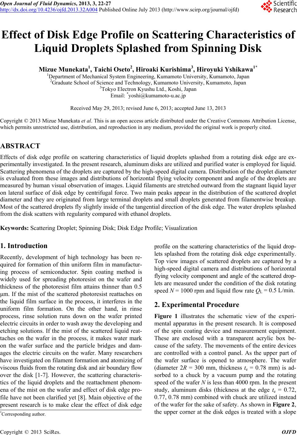
Figure 6. Horizontal flying angle and velocity of large size droplet (d > 500 μm): (a) Type A (left: angle, right: velocity); (b)
The liquid filaments are stretched outward from the
st
peaks appear in the distribution of the scat-
te
ly slightly inside of the
ta
isk edge scatter
ra
ks Mrs. Kubo, K. and Ono
REFERENCES
[1] Y. Tanasawa,Umehara, “On the
Type B (left: angle, right: velocity); (c) Type C (left: angle, right: velocity).
agnant liquid layer on the lateral surface of the disk by
the centrifugal force and inclined toward counter-rotating
direction.
Two main
red droplet diameter and they are originated from the
large terminal droplets and the small droplets generated
from the filamentwise breakup.
Most of the scattered droplets f
ngential direction on the disk edge because the liquid
filaments are stretched outward from the stagnant liquid
layer on the lateral surface of the disk.
The droplets splashed from the thin d
ther wider than that from the thick one because the
liquid filament is slim and the small droplets are gener-
ated. On the other hand, there is not apparent discrepancy
for scattering of large terminal droplets.
5. Acknowledgements
The authors would like to than,
K. for their experimental assistance.
Y. Miyasaka and M.
Filamentation of Liquid by Means of Rotating Discs, 3rd
Report, Theory of Filament Formation of Liquid,”
Transactions of JSME, Journal of Japan Society of Me-
chanical Engineers, Vol. 25, No. 156, 1959, pp. 897-905.
doi:10.1299/kikai1938.25.897
[2] M. Daikoku, H. Sunanaga and N. Nagai, “Liquid Atomi-
of Liquid Flow, and Drop Formation on the
zation from the Surface of a Rotating Body, 1st Report,
Rotating Body,” Transactions of JSME, Journal of Japan
Society of Mechanical Engineers, Series B, Vol. 54, No.
501, 1988, pp. 1170-1178.
Behavior
doi:10.1299/kikaib.54.1170
[3] N. Gregory, J. T. Stuart and W. S. Walker, “On the Sta-
bility of Three-Dimensional Boundary Layers with Ap-
plication to the Flow Due to a Rotating Disk,” Philoso-
phical Transactions of the Royal Society of London, Se-
ries A, Vol. 248, No. 943, 1955, pp. 155-199.
doi:10.1098/rsta.1955.0013
[4] R. Kobayashi, Y. Kohama and Ch. Takamadate, “Spiral
Vortices in Boundary Layer Transition Regime on a Ro-
tating Disk,” Acta Mechanica, Vol. 35, No. 1-2, 1980, pp.
71-82. doi:10.1007/BF01190058
[5] M. R. Malik, S. P. Wilkinson and S. A. Orszag, “Instabil-
ity and Transition in Rotating Disk Flow,” AIAA Journal,
Vol. 19, No. 9, 1981, pp. 1131-1138. doi:10.2514/3.7849
[6] H. L. Reed and W. S. Saric, “Stability of Three-Dimen-
sional Boundary Layers,” Annual Review of Fluid Me-
chanics, Vol. 21, 1989, pp. 235-284.
doi:10.1146/annurev.fl.21.010189.001315
[7] A. Öztekin, D. E. Bornside, R. A. Brown and P. K. Seidel,
“The Connection between Hydrodynamic Stability of Gas
Flow in Spin Coating and Coated Film Uniformity,”
Journal of Applied Physics, Vol. 77, No. 6, 1995, pp.
2297-2308. doi:10.1063/1.358751
[8] M. Munetaka, A. Noguchi, J. Nishiyama, H. Kurishima
and H. Yoshikawa, “Scattering Characteristics of Liquid
Droplets Spun Off from Rotating Disk Edge,” Journal of
Thermal Science, Vol. 21, No. 1, 2012, pp. 42-48.
doi:10.1007/s11630-012-0517-6
[9] H. S. Allen, “The Motion of a Sphere in a Viscous Fluid,”
Philosophical Magazine Series 5, Vol. 50, No. 306, 1900,
pp. 519-534. doi:0.1080/14786440009463941
Copyright © 2013 SciRes. OJFD