Optics and Photonics Journal, 2013, 3, 288-292
doi:10.4236/opj.2013.32B068 Published Online June 2013 (http://www.scirp.org/journal/opj)
Analysis of Microdisk/Microring’s Surface Roughness
Effect by Orthogonal Decomposition
Chengle Sui1, Qiangmin Wang2, Shilin Xiao1, Pingqing Li1
1State Key Lab of Advanced Optical Communication System and Networks, Shanghai Jiao Tong University, Shanghai, China
2School of Information Security Engineering Shanghai Jiao Tong University, Shanghai, China
Email: sui_chengle@sjtu.edu.cn, qmwang@sjtu.edu.cn
Received 2013
ABSTRACT
Application of micro-resonator is limited by different types of surface inhomogeneity. The 1-th derivative of inho-
mogeneity (i.e. '( )r
) affects the wave transport as well as the height of inhomogeneity (i.e. ()r
). A method
based on orthogonal decomposition is proposed to analysis both scattering mechanism respectively. Then surface
roughness effect on Q-factor of micro-disk waveguide gallery mode (WGM) resonator is investigated with our method
and the analysis fits well with FDTD simulation results.
Keywords: Orthogonal Decomposition; Micro-resonator; Surface Roughness Effect
1. Introduction
Micro-ring/micro-disk resonators are very elemental build-
ing blocks of integrated photonic device for its compact
size and especially for its high quality factor (Q-factor)
[1]. High-Q micro resonators are more and more widely
applied in lasers, modulators and bio-sensors [2-4]. How-
ever, the Quality factor of the high-index-contrast system
is still mainly constrained by scattering loss and absorp-
tion loss due to surface roughness [5].
Surface roughness effect on Q-factor and mode split-
ting are widely investigated in [5-9]. According to [10],
wave transport along the waveguide can be affected by
two scattering mechanisms: one is induced by the height
of inhomogeneity (i.e. ()r
), the other is due to the
first-order derivative of inhomogeneity (i.e. '( )r
). In
related works, the surface roughness is modeled as a
random variable, and the scattering loss is calculated
stochastically. But all of these methods either fail to ob-
serve the effect of or are too complex for calculation,
because they cannot analyze independently the scattering
loss due to both scattering mechanism. Therefore, if a
simulation is needed to conduct for analysis, we cannot
calculate the result accurately. For example, in [9], sev-
eral Nano scale circular holes are carved evenly along the
microdisk to make intentional surface roughness. In [6],
random distributed inhomogeneity is approached by a
number of randomly spaced rectangle asperities. All these
approximation method is not very accurate, and cannot
help us to further our understanding on the underlying
scattering mechanism.
In this paper, a method based on orthogonal decompo-
sition is proposed to simplify the calculation of surface
roughness effect without losing accuracy. We try to ap-
proach the inhomogeneity infinitely by a linear combina-
tion of orthogonal basis we proposed, and then we can
analyze the effect of ()r
and '( )r
independently
by carefully choosing proper orthogonal basis.
The paper is organized in the following way: in Sec-
tion 2, the model of orthogonal basis is introduced, and
then its correctness is proved by Fourier Transform. At
the end of Section II, the utilization of the proposed or-
thogonal basis is studied in detail. In Section 3, we ana-
lyze the surface roughness effect on Q-factor of micro-
disk resonator at first. Then we conduct the analysis and
FDTD simulation based on our method, the result of
which validates our derivation.
2. Model
2.1. Notations
The side boundary of micro resonator is rough, and is
shaped by closed contour S along the basis parallel to z
basis, as depicted in Figure 1. The distance from center
point to each side boundary is given by
()(), [, ]rRr
 
  (1)
where R is the average radius and is a random variable
with zero mean. The correlation function of is often fitted
to Gauss distribution, i.e.
*2 2
12 12
()( )exp[()/]
c
rr L
 
 2
(2)
Copyright © 2013 SciRes. OPJ
C. L. SUI ET AL. 289
where Lc is the correlation length and σ is the root mean
square (rms) value of surface deviations. In addition, we
have
expectation operator
2-norm
()F
[(
elementary function
)]
i
k
f
x i-th square of ()
k
f
x
()
i
k
f
x i-th order derivative of ()
k
f
x
Figure 2 shows one period of a sequence of orthogo-
nal basis {()}
i
f
x, which is orthogonal with each other,
i.e.
1
() ()0
ij
ij
fxfxdx ij

(3)
'' '
() ()() ()
1
0
ij ij
xfxdxf xfxdx
ij
ij

 

(4)
Finally, we define the period of orthogonal basis as L.
Figure 1. SNR degradation as function of laser line width.
Figure 2. Schematic of orthogonal basis in one period.
2.2. Orthogonal Decomposition
Now we’ll prove the fact by Fourier Transform that side
wall inhomogeneity can be approached by orthogonal basis
i
f
through orthogonal decomposition. The Fourier
Transform of fk(x) is given by
21
0
0
2
0
2
()(1)exp[2 ()/]
(/)
(/)
k
i
kkn
in
kn
f
xj
sinn lL
hnL


 

 nxilL
(5)
According to [12-13], there would always be a linear
combination of
i
f
that can approach ()r
infi-
nitely by meeting the condition
1
lim( )( )0
n
kk
nk
Af r



(6)
Therefore, if the orthogonal basis and its weight are
carefully chosen, the orthogonal basis we proposed can
accurately approximate the transmittance of micro reso-
nator with rough surface.
For a specific resonator, several modes may be propa-
gated along the waveguide. As it is stated in [5],
2
0
2
3/2 2
*
1
()exp( )
2
()exp( )
2( )
exp 2
k
k
k
cc
kk
rajk
ar jnd
LkL
aa RR



 
 








(7)
Reference [5] shows that each micro resonator is
matched with a sequence of ak , and each ak corresponds
to the mode splitting for resonant mode with azimuthal
order k.
Now the way of getting the parameter of orthogonal
basis we proposed will be revealed. Comparing (5) with
(7), if we simply look into one specific mode splitting
with azimuthal order k, the surface roughness effect can
be accurately approached by one specific orthogonal ba-
sis
k
f
if only
22 /2
R
Lpp
 
N
 (8)
221
0
0
2
0
2
3/2 2
0
(/)
(1)exp(2/)
(/)
2( )
exp 2
k
i
i
cc
sinn lL
hj
nL
LnL
RR




 





ilL
(9)
Here, 0
I
is normalized random variable whose mean
value is 1. If 2LR
, it’s reasonable to assume that
orthogonal basis spreads over micro resonator to infinite
period. From (8), we can get that if the azimuth
Copyright © 2013 SciRes. OPJ
C. L. SUI ET AL.
290
doesn’t equal to 0, the value of 2/RL
won’t be an
integer, which means we cannot evenly distribute every
period of orthogonal basis around the circle. But if L is
chosen to be a very large number, the approximate error
can be neglected. According (9), if L is given, we can get
a simple relationship between h and .
0
Phase shift due to rough surface should also be taken
into consideration when we investigate the mode splitting
in micro-disk. The phase shift is uniformly distributed in
the interval
l
[0,2 )
, so the orthogonal basis can be modi-
fied to be i
{() efz xp[ 2(0,1)j N]}
. Here is a
random variable that uniformly distributes in the interval
.
(0,1)N
[0,1)
If we have to analyze the effect of N modes with dif-
ferent azimuthal orders, we can find N-dimensional or-
thogonal basis from {()}
i
f
z to approximate the effect
of inhomogeneity, according to the representation theo-
rem in strictly normed linear space[13]. The weights for
each orthogonal basis can be obtained by matrix trans-
form.
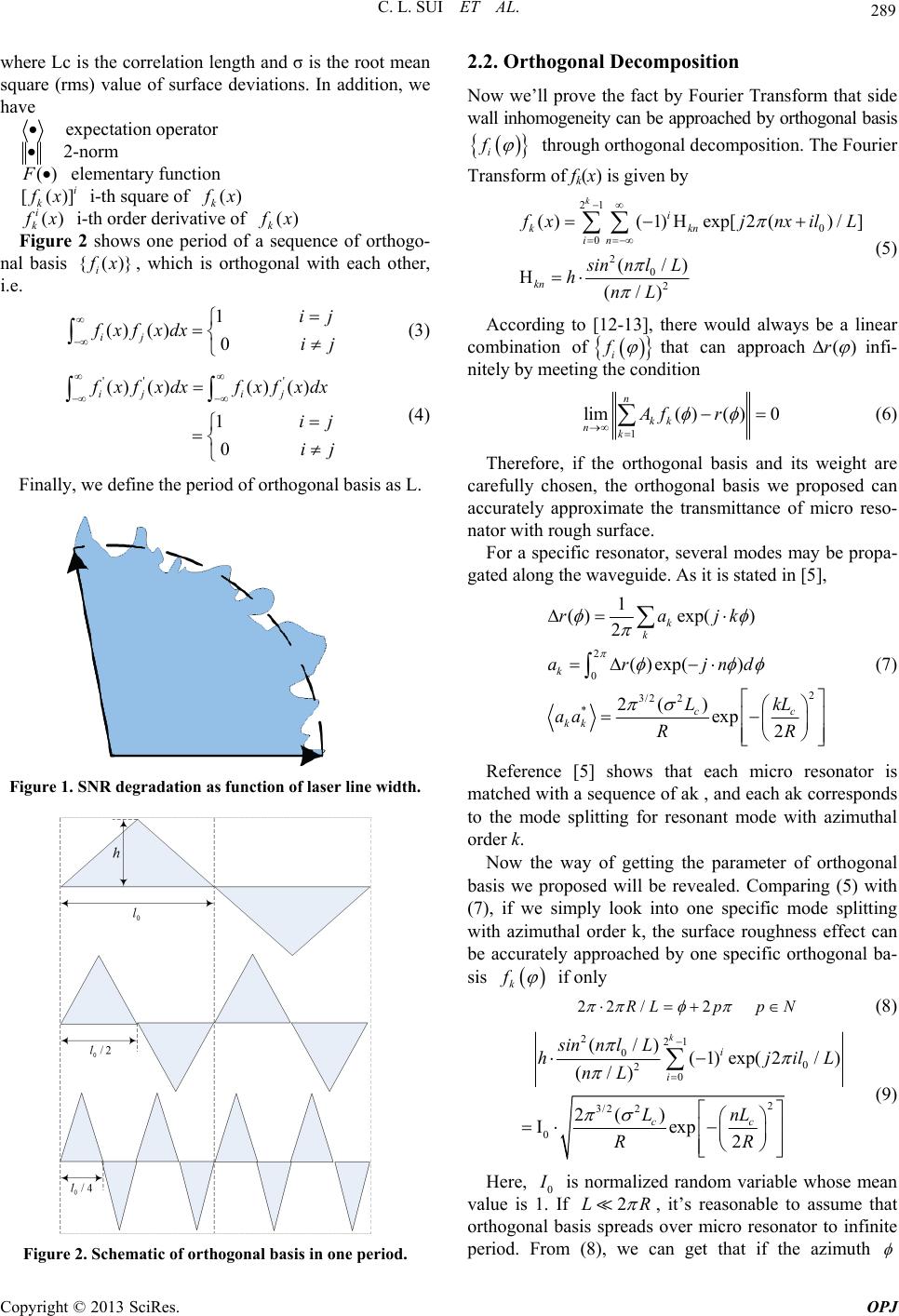
Surface roughness effect caused by ()r
and '( )r
can be represented as an elementary function of ()r
and '( )r
, so we can easily obtain [12]:



[()]
['()]
ii
ii
kk
fx
fx
[()]
['()]
kk
Ffx F
FfxF
(10)
Thus, if 0
2
0|()|
l
k
f
xdx
keeps static when the value of
0
l changes, the value of [()
i
k]
f
x will be the same,
which means the ()r
nduced roughness effect will not
change. Similarly by keeping 0
2|'()|
l
i
0k
f
xdx
static, we can
keep the effect of r'()
unchanged even though the
value of 0
l changes. In this way, we can analyze the
effect of ()r
and r'()
respectively.
3. Simulation and Result Analysis
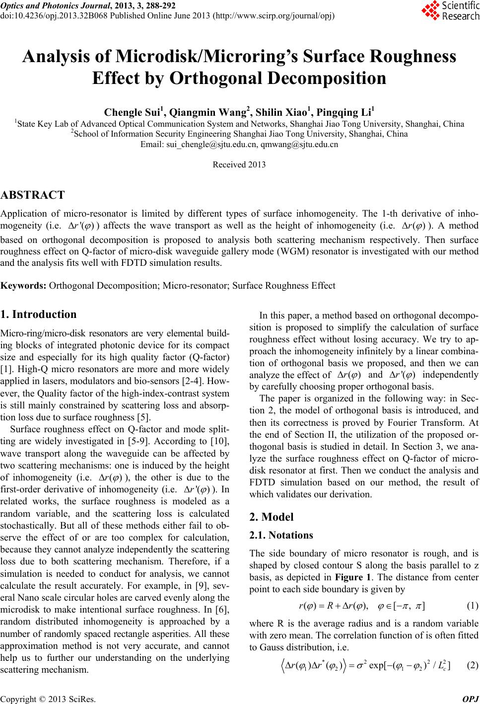
To confirm the theory above, we analysis the surface
roughness effect on Q-factor of micro-disk as an example.
Because we mainly concentrate on the power from the
in/out port, the standard operator norm defined in [14] is
carefully applied to estimate the transmittance of micro-
disk. The operator norm is defined as:
2
,0
(, )
sup (,)
xSx
Ex Ex
Exx

(11)
According to [6], the height of inhomogeneity ()r
induced scattering for 2D micro-disk resonator can be
written as
2
2
()
22
()
(1 )
hK
E
 (12)
and if the surface is rather smooth, which means is
fairly small, it is the height of inhomogeneity )(r
,
rather than its first derivative '( )r
, that is the-
nant factor that leads to scattering loss.
To compare the deviation above wit
domi
orthogonal
is 3μm.
h the
ba
-disk
Th
sis method we proposed in Section 2, we conduct FDTD
simulations with on Ge whisper gallery mode (WGM)
micro-disk resonator. The simulation tool is FDTD solu-
tion release 8.0. Micro-resonators based on Ge are more
and more popular for the merit of especially high
Q-factor and graft ability on Silicon based device [11].
It’s of great value to have a thoroughly research on the
surface roughness effect of Ge micro-disk.
In our simulation, the diameter of micro
e waveguide coupled along the disk is made of SiO2
with 0.5μm width at 200nm distance from the disk. N =
1.42 is used as waveguide’s reflective index and a value
of n = 4.2 for Ge micro disk. Surface roughness is ma-
nipulated by orthogonal basis {()}
i
f
x and details of
orthogonal basis are carefully calculated following the
method described in Section 2. When we investigate the
propagation of fundament TE/TM mode, the mode num-
ber n in (9) is set to 1. Mean variance of roughness 2
is 1nm and correlation length c
L is 50 nm. Accord
to (8-9), if /4
ing
, we can obtain

2
0
2
/ (18
sin [0.01895(18)]0.0379(18)]
18 /52.8
0.4107
R
pl pl
p0
16 )L p
1 exp[hj
(13)
from (1e larger p is

3) that thIt’s easy to observe
m
, the
ore accurate we can calculate because we need to fix
the value of L to make 2/RL
to be an integer. In our
simulation, p is set to be 4, and the relationship between
0
,hl indicated in (17) can be further simplified.
s it is stated above, by keeping 0
2|()|
l
k
A0
f
xd
x static,
acss due to cording to (10), the scattering r'( )
lo
changes with 0
l increasing from 150nm to 400nm
the effect of ()r while
will be the same. Similarly, if the
value of 0
2|
l
0|'()
k
f
xdx
s static when 0
l s varied, the
scattering ()r
loss due to
will chan e accordingly g
and the effect of r'( )
kee static.
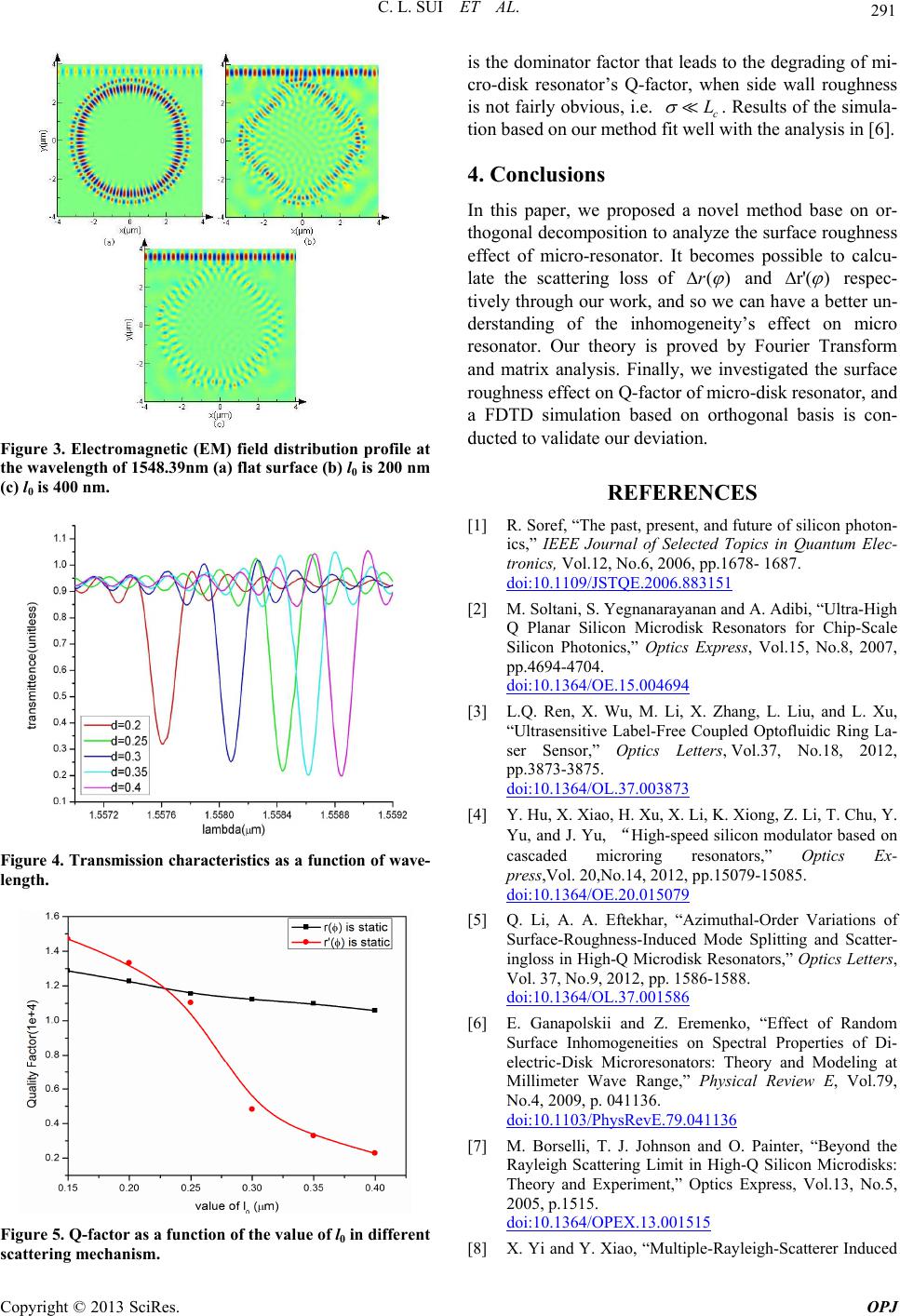
Figure 3 showlectromagnetic
p
e
s
s the (EM) field distri-
bution when the effect of ()r
varies with the in-
crease of 0
l. Obviously, Q-f micro-disk resona-
tor decreasramatically as the height of inhomogeneity
increases. On the contrary, if the value of 0
2|()|
l
k
actor of
e d
0
f
xdx
is a constant, the Q-factor almost keeps u nchanged with
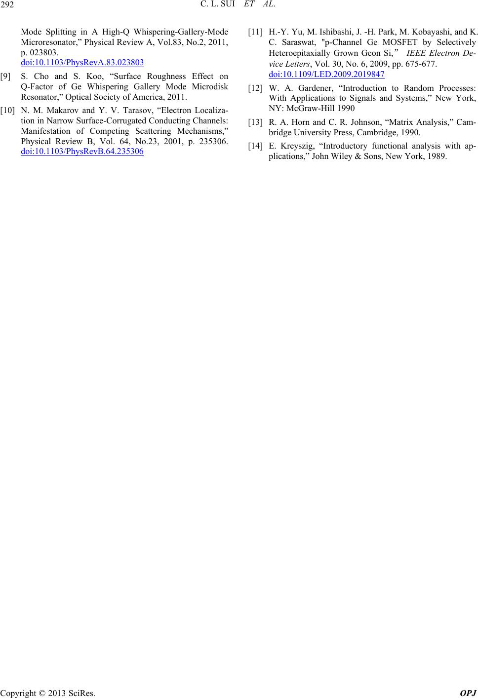
the alternative of 0
l, as depicted in Figure 4. Figure 5
reveals different sensitivity of micro-resonator’s Q-factor
on the two scattering mechanism. The effect of ()r
Copyright © 2013 SciRes. OPJ
C. L. SUI ET AL. 291
Figure 3. Electromagnetic (EM) field distribution profile at
the wavelength of 1548.39nm (a) flat surface (b) l0 is 200 nm
(c) l0 is 400 nm.
Figure 4. Transmission characteristics as a function o f wave-
length.
is the dominator factor that leads to the degrading of mi-
cro-disk resonator’s Q-factor, when side wall roughness
is not fairly obvious, i.e. c
L
. Results of the simula-
tion based on our method fit well with the analysis in [6].
4. Conclusions
In this paper, we proposed a novel method base on or-
thogonal decomposition to analyze the surface roughness
effect of micro-resonator. It becomes possible to calcu-
late the scattering loss of ()r
and r'( )
respec-
tively through our work, and so we can have a better un-
derstanding of the inhomogeneity’s effect on micro
resonator. Our theory is proved by Fourier Transform
and matrix analysis. Finally, we investigated the surface
roughness effect on Q-factor of micro-disk resonator, and
a FDTD simulation based on orthogonal basis is con-
ducted to validate our deviation.
REFERENCES
[1] R. Soref, “The of silicon photon-
ics,” IEEE Jo in Quantum Elec-
past, present, and future
urnal of Selected Topics
tronics, Vol.12, No.6, 2006, pp.1678- 1687.
doi:10.1109/JSTQE.2006.883151
[2] M. Soltani, S. Yegnanarayanan and A. Adibi,
Q Planar Silicon Microdisk Reson
“Ultra-High
ators for Chip-Scale
Silicon Photonics,” Optics Express, Vol.15, No.8, 2007,
pp.4694-4704.
doi:10.1364/OE.15.004694
[3] L.Q. Ren, X. Wu, M. Li, X.
“Ultrasensitive Label-Free C
Zhang, L. Liu, and L. Xu,
oupled Optofluidic Ring La-
ser Sensor,” Optics Letters, Vol.37, No.18, 2012,
pp.3873-3875.
doi:10.1364/OL.37.003873
[4] Y. Hu, X. Xiao, H. Xu, X. Li,
Yu, and J. Yu,High-spee
K. Xiong, Z. Li, T. Chu, Y.
d silicon modulator based on
cascaded microring resonators,” Optics Ex-
press,Vol. 20,No.14, 2012, pp.15079-15085.
doi:10.1364/OE.20.015079
[5] Q. Li, A. A. Eftekhar, “Azimuthal-Order V
Surface-Roughness-Induced
ariations of
Mode Splitting and Scatter-
ingloss in High-Q Microdisk Resonators,” Optics Letters,
Vol. 37, No.9, 2012, pp. 1586-1588.
doi:10.1364/OL.37.001586
[6] E. Ganapolskii and Z. Eremenko,
Surface Inhomogeneities on
“Effect of Random
Spectral Properties of Di-
electric-Disk Microresonators: Theory and Modeling at
Millimeter Wave Range,” Physical Review E, Vol.79,
No.4, 2009, p. 041136.
doi:10.1103/PhysRevE.79.041136
[7] M. Borselli, T. J. Johnson and O. Painter
Rayleigh Scattering Limit in High-Q Silicon Mic
, “Beyond the
rodisks:
Theory and Experiment,” Optics Express, Vol.13, No.5,
2005, p.1515.
doi:10.1364/OPEX.13.001515
[8] X. Yi and Y. X
Figure 5. Q-factor as a function of the value of l0 in differ
scattering mechanism.
ent iao, “Multiple-Rayleigh-Scatterer Induced
Copyright © 2013 SciRes. OPJ
C. L. SUI ET AL.
Copyright © 2013 SciRes. OPJ
292
Whispering-Gallery-ModeMode Splitting in A High-Q
Microresonator,” Physical Review A, Vol.83, No.2, 2011,
p. 023803.
doi:10.1103/PhysRevA.83.023803
[9] S. Cho an
Q-Factor of Ge Whispering Gall
d S. Koo, “Surface Roughness Effect on
ery Mode Microdisk
Channels:
Resonator,” Optical Society of America, 2011.
[10] N. M. Makarov and Y. V. Tarasov, “Electron Localiza-
tion in Narrow Surface-Corrugated Conducting
Manifestation of Competing Scattering Mechanisms,”
Physical Review B, Vol. 64, No.23, 2001, p. 235306.
doi:10.1103/PhysRevB.64.235306
[11] H.-Y. Yu, M. Ishibashi, J. -H. Park, M. Kobayashi, and K.
C. Saraswat, "p-Channel Ge MOSFET by Selectively
Heteroepitaxially Grown Geon Si, IEEE Electron De-
vice Letters, Vol. 30, No. 6, 2009, pp. 675-677.
doi:10.1109/LED.2009.2019847
[12] W. A. Gardener, “Introduction to Random Processes:
With Applications to Signals and Systems,” New York,
NY: McGraw-Hill 1990
[13] R. A. Horn and C. R. Johnson, “Matrix Analysis,” Cam-
bridge University Press, Cambridge, 1990.
[14] E. Kreyszig, “Introductory functional analysis with ap-
plications,” John Wiley & Sons, New York, 1989.