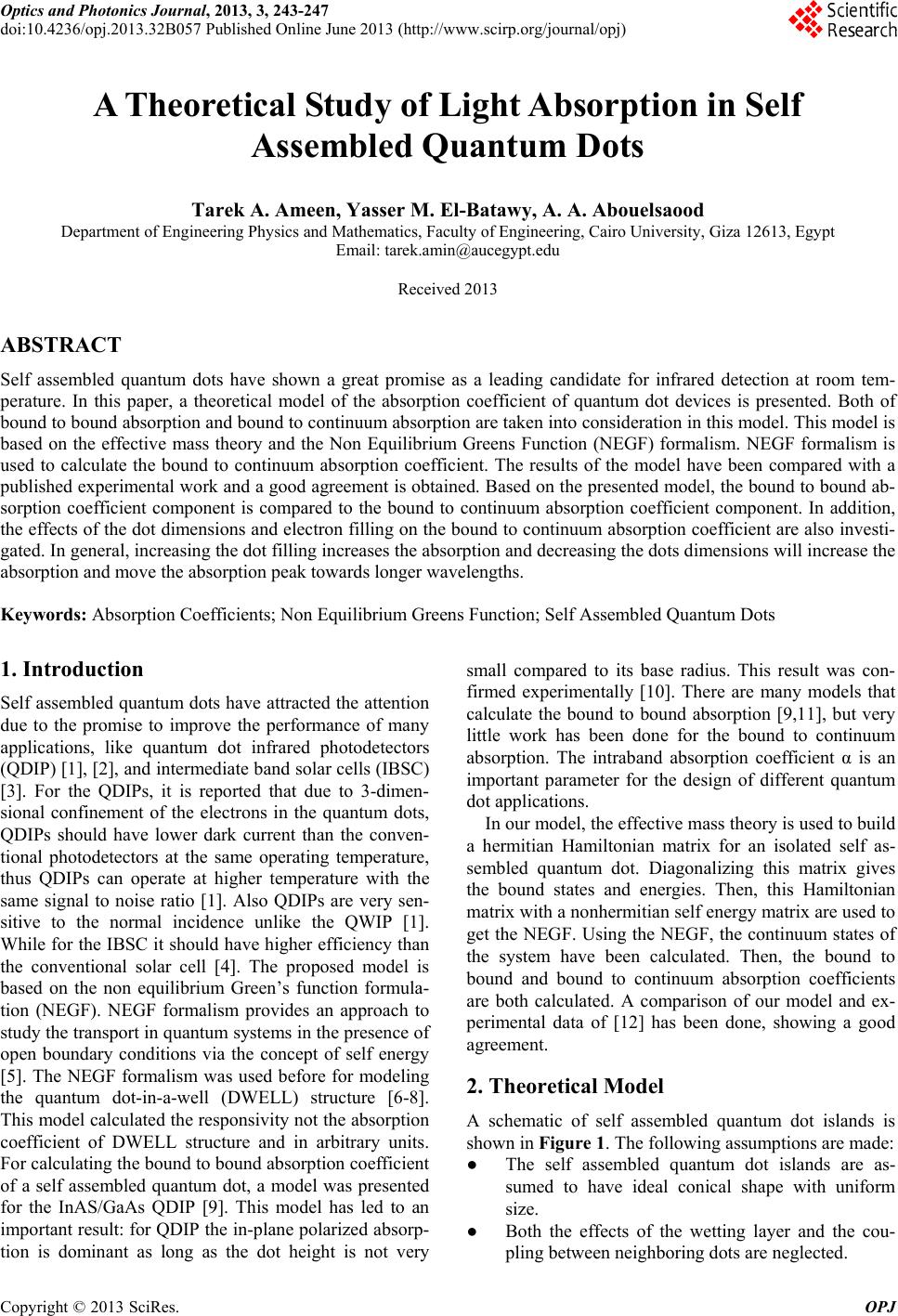
 Optics and Photonics Journal, 2013, 3, 243-247 doi:10.4236/opj.2013.32B057 Published Online June 2013 (http://www.scirp.org/journal/opj) A Theoretical Study of Light Absorption in Self Assembled Quantum Dots Tarek A. Ameen, Yasser M. El-Batawy, A. A. Abouelsaood Department of Engineering Physics and Mathematics, Faculty of Engineering, Cairo University, Giza 12613, Egypt Email: tarek.amin@aucegypt.edu Received 2013 ABSTRACT Self assembled quantum dots have shown a great promise as a leading candidate for infrared detection at room tem- perature. In this paper, a theoretical model of the absorption coefficient of quantum dot devices is presented. Both of bound to bound absorption and bound to continuum absorption are taken into consideration in this model. This model is based on the effective mass theory and the Non Equilibrium Greens Function (NEGF) formalism. NEGF formalism is used to calculate the bound to continuum absorption coefficient. The results of the model have been compared with a published experimental work and a good agreement is obtained. Based on the presented model, the bound to bound ab- sorption coefficient component is compared to the bound to continuum absorption coefficient component. In addition, the effects of the dot dimensions and electron filling on the bound to continuum absorption coefficient are also investi- gated. In general, increasing the dot filling increases the absorption and decreasing the dots dimensions will increase the absorption and move the absorption peak towards longer wavelengths. Keywords: Absorption Coefficients; Non Equilibrium Greens Function; Self Assembled Quantum Dots 1. Introduction Self assembled quantum dots have attracted the attention due to the promise to improve the performance of many applications, like quantum dot infrared photodetectors (QDIP) [1], [2], and intermediate band solar cells (IBSC) [3]. For the QDIPs, it is reported that due to 3-dimen- sional confinement of the electrons in the quantum dots, QDIPs should have lower dark current than the conven- tional photodetectors at the same operating temperature, thus QDIPs can operate at higher temperature with the same signal to noise ratio [1]. Also QDIPs are very sen- sitive to the normal incidence unlike the QWIP [1]. While for the IBSC it should have higher efficiency than the conventional solar cell [4]. The proposed model is based on the non equilibrium Green’s function formula- tion (NEGF). NEGF formalism provides an approach to study the transport in quantum systems in the presence of open boundary conditions via the concept of self energy [5]. The NEGF formalism was used before for modeling the quantum dot-in-a-well (DWELL) structure [6-8]. This model calculated the responsivity not the absorption coefficient of DWELL structure and in arbitrary units. For calculating the bound to bound absorption coefficient of a self assembled quantum dot, a model was presented for the InAS/GaAs QDIP [9]. This model has led to an important result: for QDIP the in-plane polarized absorp- tion is dominant as long as the dot height is not very small compared to its base radius. This result was con- firmed experimentally [10]. There are many models that calculate the bound to bound absorption [9,11], but very little work has been done for the bound to continuum absorption. The intraband absorption coefficient α is an important parameter for the design of different quantum dot applications. In our model, the effective mass theory is used to build a hermitian Hamiltonian matrix for an isolated self as- sembled quantum dot. Diagonalizing this matrix gives the bound states and energies. Then, this Hamiltonian matrix with a nonhermitian self energy matrix are used to get the NEGF. Using the NEGF, the continuum states of the system have been calculated. Then, the bound to bound and bound to continuum absorption coefficients are both calculated. A comparison of our model and ex- perimental data of [12] has been done, showing a good agreement. 2. Theoretical Model A schematic of self assembled quantum dot islands is shown in Figure 1. The following assumptions are made: ● The self assembled quantum dot islands are as- sumed to have ideal conical shape with uniform size. ● Both the effects of the wetting layer and the cou- pling between neighboring dots are neglected. Copyright © 2013 SciRes. OPJ 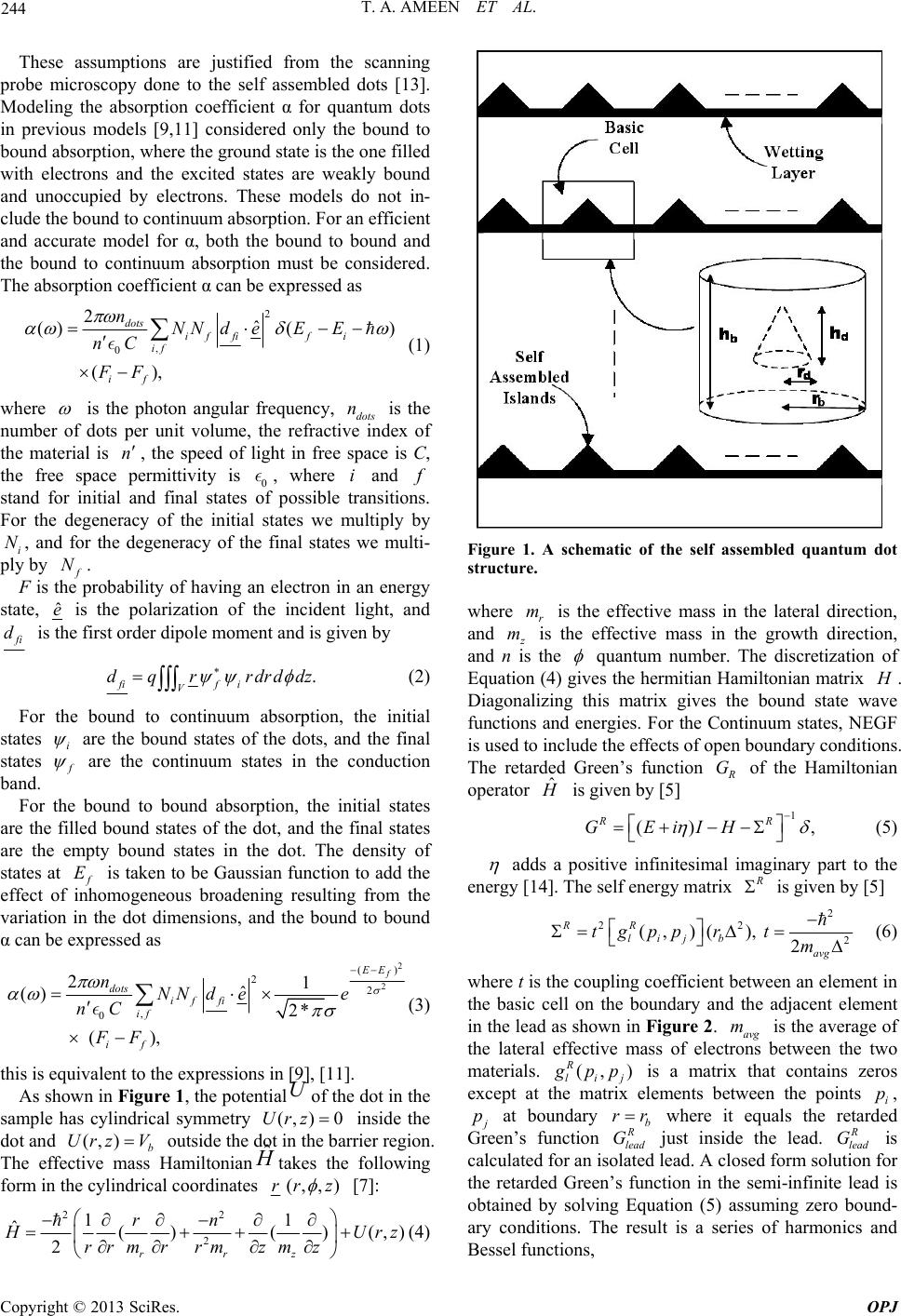 T. A. AMEEN ET AL. 244 These assumptions are justified from the scanning probe microscopy done to the self assembled dots [13]. Modeling the absorption coefficient α for quantum dots in previous models [9,11] considered only the bound to bound absorption, where the ground state is the one filled with electrons and the excited states are weakly bound and unoccupied by electrons. These models do not in- clude the bound to continuum absorption. For an efficient and accurate model for α, both the bound to bound and the bound to continuum absorption must be considered. The absorption coefficient α can be expressed as 2 , 0 2ˆ ()( ) (), dots if fifi if if nNN deEE nC FF (1) where is the photon angular frequency, dots is the number of dots per unit volume, the refractive index of the material is , the speed of light in free space is C, the free space permittivity is 0, where and n i n stand for initial and final states of possible transitions. For the degeneracy of the initial states we multiply by i, and for the degeneracy of the final states we multi- ply by N N. F is the probability of having an electron in an energy state, ˆ e is the polarization of the incident light, and i d is the first order dipole moment and is given by . fif i V dqr rdrddz (2) For the bound to continuum absorption, the initial states i are the bound states of the dots, and the final states are the continuum states in the conduction band. For the bound to bound absorption, the initial states are the filled bound states of the dot, and the final states are the empty bound states in the dot. The density of states at E is taken to be Gaussian function to add the effect of inhomogeneous broadening resulting from the variation in the dot dimensions, and the bound to bound α can be expressed as 2 2 () 2 2 , 0 21 ˆ () 2* (), f EE dots if fi if if nNN dee nC FF (3) this is equivalent to the expressions in [9], [11]. As shown in Figure 1, the potentialUof the dot in the sample has cylindrical symmetry inside the dot and outside the dot in the barrier region. The effective mass Hamiltoniantakes the following form in the cylindrical coordinates (, )Urz 0 ˆ H (, )b Urz V (,rr , )z [7]: 22 2 11 ˆ ()()(, 2rz r rn Figure 1. A schematic of the self assembled quantum dot structure. where r m is the effective mass in the lateral direction, and m is the effective mass in the growth direction, nd e an is th quantum number. The discretization of Equatio4) gives the hermitian Hamiltonian matrix n ( . Diaglizing this matrix gives the bound state wave functions and energies. For the Continuum states, NEGF is used to include the effects of open boundary conditio. The retarded Green’s function ona ns G of the Hamiltonian operator ˆ is given by [5] 1 () , RR GEiIH (5) add positive infinites asimal imaginary part to the energy [14]. The self energy matrix is given by [5] 2 22 2 (,)(), 2 RR lij b avg tgpp rt m (6) where t is the coupling coefficient between an elem the basic cell on the boundary and the adjacent el in the lead as shown in Figure 2. is the average of ent in ement ) Urz rrm rzmz rm (4) avg the lateral effective mass of electrons between the two materials. (, ) R lij m pp is a matrix that contains zeros except at the matrix elements be the points i p, tween p at boundary b rr where it equals the retarded Green’s funct just inside the lead. R lead G is calculated for an isolated lead. A closed form solution for retarded Green’ction in the semi-infinite lead is obtained by solvinguation (5) assuming zerond- ary conditions. The result is a series of harmonics and Bessel functions, ion R lead G thes fun Eq bou Copyright © 2013 SciRes. OPJ 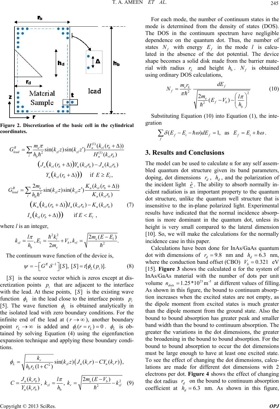 T. A. AMEEN ET AL. 245 Figure 2. Discretization of the basic cell in the cylindrical coordinates. (1) (( )) sin( )sin() Renrlb lead l mHkr Gkzkz 2( 1) () ()() () ()if , (( ) ()) zl zl bnrlb nrlbnrlb nrlb nrlb l hH kr JkrYkr Jkr YkrE E 2 2( sin( )sin() if () ()()( , ) () (( ) ()) Renr leadzl zl lnrlb b n rlbnrlbnrlb nr llb mKk Gkzkz Kkr h KkrIkr Kkr IEEkr ()) lb r (7) where l is an integer, 22 2 2( ) ,., lel b rl e kmEE l kE Vk m The continuum wave function of the device is, (8) at dis- n points that are adjacent to t e lead. points, is the ex fu 2 zl l b h 1 [], [][()]. RLi GSStp []S is the source vector which is zeros except cretizatio with th nctio i p At these he interface isting wave []S n in the lead close to the interface points i p [5]. The wave function is obtained analytically in the isolated lead with zero bouny conditions. For the infinite eof the lead at (r), another bounda point L r is added ad ()0 lL rr dar nd ry n . is ob- tained by solving Equation (4) using the eigenfunction expansion technique and applyese boundary condi- tions. ing th 2sin()( )( ), r Lzlnrnr kkzJkrCYkr (1 ) bL hr C 2 2 ()2( ) , , () nrbe b lr nrb b JkrmEV l Ckk Ykrh zl k 9) For each mode, the number of continuum states in the mode is determined from the density of states (D Th ( OS). e DOS in the continuum spectrum have negligible dependence on the quantum dot. Thus, the number of states N with energy E in the mode l is calcu- lated in the absence of the dot potential. The device shape becomes a solid disk made from the barrier mate- rial with radius r and height b h. N is obtained using ordinary DOS calculations, 2 2 f eL f dE mr Nm (10) 2 2() efb b l EV h Substituting Equation (10) into Equation (1), the inte- gration ()1, fi f f EE dE as . fi EE 3. Results and Conclusion The model can be used to calculate α for any self assem- its band parameters, s bled quantum dot structure given doping, dot dimensions d r, d h, and the polarization of the incident light ˆ e. The ability to absorb normally in- cident radiation is an important property to the quantum dot structure, unlike the quantum well structure that is insensitive to the in-plane polarized light. Experimental results have indicated that the normal incidence absorp- tion is more dominant in the quantum dot, unless its height is very small compared to the lateral dimension [10]. So, we will make the calculations for the normally incidence case in this paper. Calculations have been done for InAs/GaAs quantum dot with dimensions of 9.8 d r nm and 6.3 d h nm, where the conduction band offset (CBO) 0.321 b V eV [15]. Figure 3 shows the calculated α for the system of InAs/GaAs material with the number of dot unit volume 2-31 1.25 m*10 dots n at different values of filling. As shown in this figure, the bound to continuum absorp- tion increases when the excited states are not empty, as the dipole moment from excited states is much greater than the dipole moment from the ground state. Also the bound to bound absorption has greater peak and smaller band width than the bound to continuum absorption. The greater the variations in the dot dimensions, the greater the broadening in the bound to bound absorption. For the bound to bound absorption to occur the dot dimensions must be large enough to have at least one excited state. To see the effect of changing the dot dimensions, calcu- lations are made for different dot dimensions with 2 electrons per dot. Figure 4 shows the effect of changing the dot radius d r on the bound to continuum absorption coefficient at 6.3 d h s per nm. As shown in this figure, Copyright © 2013 SciRes. OPJ 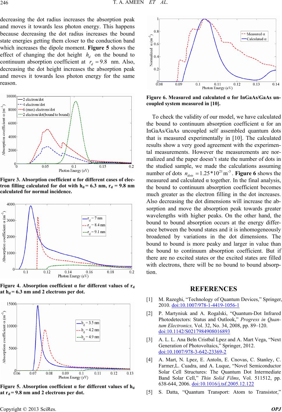 T. A. AMEEN ET AL. 246 decreasing the dot radius increases the absorption peak and moves it tards less photon energy. This happens because decrea dot radius increases the bound state energies getting them closer to the conduction band which increases the dipole moment. Figure 5 shows the effect of changing the dot height d h on the bound to continuum absorption coefficient at 9.8 d r nm. Also, decreasing the dot height increases the absorption peak and moves it towards less photon energy for the same reason. ow sing the Figure 3. Absorption coefficient α fores of elec- tron filling calculated for dot with hd = 9.8 nm calculated for normal incidence. diffe d = 6. rent cas 3 nm, r Figure 4. Absorption coefficient α fornt values of rd at hd = 6.3 nm and 2 electrons per dot. differ e Figure 5. Absorption coefficient α fornt values of hd at rd = 9.8 nm and 2 electrons per dot. differ e Figure 6. Measured and calculated α for InGaAs/GaAs un- coupled system measured in [10]. To check the validity of our model, we have calculated the bound to continuum absorption coefficient α for an InGaAs/GaAs uncoupled self assembled quantum dots that is measured experimentally in [10]. The calculated results show a very good agreement with the experimen- tal measurements. However the measurements are nor- malized and the paper doesn’t state the number of dots in the studied sample, we made the calculations assuming number of dotsFigure 6 shows the measured and the final analysis s will increase the ab- o hwill be no bou 2-31 1.25 m*10 dots n. calculated α together. In, the bound to continuum absorption coefficient becomes much greater as the electron filling in the dot increases. lso decreasing the dot dimensionA srption and move the absorption peak towards greater wavelengths with higher peaks. On the other hand, the bound to bound absorption occurs at the energy differ- ence between the bound states and it is inhomogeneously broadened by variations in the dot dimensions. The bound to bound is more peaky and larger in value than the bound to continuum absorption coefficient. But if there are no excited states or the excited states are filled with electrons, tere nd to bound absorp- tion. REFERENCES [1] M. Razeghi, “Technology of Quantum Devices,” Springer, 2010. doi:10.1007/978-1-4419-1056-1 [2] P. Martyniuk and A. Rogalski, “Quantum-Dot Infrared Photodetectors: Status and Outlook,” Progress in Quan- tum Electronics, Vol. 32, No. 34, 2008, pp. 89–120. doi:10.1142/S0217984908016893 [3] A. L. L. Ana Beln Cristbal Lpez and A. Mart Vega, “Next Generation of Photovoltaics,” Springer, 2012. doi:10.1007/978-3-642-23369-2 [4] A. Mart, N. Lpez, E. Antoln, E. Cnovas, C. Stanley, C. Farmer,L. Cuadra, and A. Luque, “Novel Semiconductor Solar Cell Structures: The Quantum Dot Intermediate Band Solar Cell,” , Vol. 511512, pp. 638-644, 20062.122 Thin Solid Films . doi:10.1016/j.tsf.2005.1 [5] S. Datta, “Quantum Transport: Atom to Transistor,” Copyright © 2013 SciRes. OPJ  T. A. AMEEN ET AL. Copyright © 2013 SciRes. OPJ 247 Cambridge University Press, 2005. doi:10.1017/CBO9781139164313 [6] M. A. Naser, M. J. Deen and D. A. Thompson, “Spectral Function of InAs/InGaAs Quantum Dots in A Well De- tector Using Green’s Function,” Journal of Applied Ph ics, Vol. 100, No. 9, 2006, p. 09310 ys- 2. doi:10.1063/1.2372572 [7] M. A. Naser, M. J. Deen and D. A. Thompson Function and Responsivity of Resonant Tunn , “Spectra eling and l Superlattice Quantum Dot Infrared Photodetectors Using Green’s Function,” Journal of Applied Physics, Vol. 102, No. 8, 2007, p. 083108. doi:10.1063/1.2799075 [8] M. A. Naser, M. J. Deen and D. A. Thompson, “Theo- retical Modeling of Dark Current in Quantum Dot Infra- red Photodetectors Using Nonequilibrium Green’s Func- tions,” Journal of Applied Physics, Vol. 104, No. 1, 2008, p. 014511. doi:10.1063/1.2952014 [9] B. Kochman, A. Stiff-Roberts, S. Chakrabarti, J. Phillips, S. Krishna, J. Singh and P. Bhattacharya, “Absorption, Carrier Lifetime, and Gain in InAs-GaAs Quantum-Dot Infrared Photodetectors,” IEEE Journal of Quantum Elec- tronics, Vol. 39, 2003, pp. 459-467. doi:10.1109/JQE.2002.808169 [10] A. M. Adawi, E. A. Zibik, L. R. Wilson, A. Lemaˆıtre, J. W. Cockburn, M. S. Skolnick, M. Hopkinson, G. Hill, S. L. Liew and A. G. Cullis, “Strong In-Plane Polarized In- Traband Absorption in Vertically Aligned Ingaas/gaas Quantum Dots,” Applied Physics Letters, Vol. 82, No. 20, 2003, pp. 3415–3417. doi:10.1063/1.1575931 [11] K. Lantz and A. Stiff-Roberts, “Calcu Absorption Coefficients in Org lation of Intraband anic/Inorganic Nanocom- posites: Effects of Colloidal Quantum Dot Surface Ligand and Dot Size,” IEEE Journal of Quantum Electronics, Vol. 47, 2011, pp. 1420-1427. doi:10.1109/JQE.2011.2169235 [12] B. Aslan, H. C. Liu, M. Korkusinski, S.-J. Cheng and P. Hawrylak, “Response Spectra from Mid- to Far-Infrared, Polarization Behaviors, and Effects of Electron Numbers in Quantum-Dot Photodetectors,” Applied Physics Letters, Vol. 82, No. 4, 2003, pp. 630-632. doi:10.1063/1.1540728 [13] H. Lee, H. Park and T. Kim Self-Assembled CdTe Quantum , “Formation Mode of Dots Directly Grown on Gaas Substrates,” Journal of Crystal Growth, Vol. 291, No. 2, 2006, pp. 442–447. doi:10.1016/j.jcrysgro.2006.03.018 [14] S. Datta, “Electronic Transport in Mesoscopic Systems,” Cambridge University Press, 1996. doi:10.1063/1.2807624 [15] I. Vurgaftman, J. R. Meyer and L. R. Ram-Mohan, “Band Parameters for iii–v Compound Semiconductors and Their Alloys,” Journal of Applied Physics, Vol. 89, No. 11, 2001, pp. 5815–5875. doi:10.1063/1.1368156
|