Optics and Photonics Journal, 2013, 3, 212-216
doi:10.4236/opj.2013.32B050 Published Online June 2013 (http://www.scirp.org/journal/opj)
Channel Simulation of Non-imaging Optical MIMO
Communication
Jiao Feng, Liwei Ding, Yongjin Wang
Institute of Communication Technology, Nanjing University of Posts and Telecommunications, Jiangsu, China
Email: wangyj@njupt.edu.cn
Received 2013
ABSTRACT
This paper reports a channel simulation of an indoor optical wireless multiple-input-multiple-output (MIMO) system
with non-imaging receivers. The system consists of a 2×2 array of white light-emitting diodes (LEDs) and 2×2 array
of PDs. An overview of the model specifications, channel impulse response and channel capacity are demonstrated in
this paper. The distribution of the first reflection is analyzed. The effect of SNR and the location of receivers on
non-imaging optical MIMO communications are investigated. In addition, by moving the receivers, the optimal location
of the communication is found.
Keywords: MIMO; LEDs; Non-imaging; Channel Impulse Response; Channel Capacity
1. Introduction
Energy-saving is gradually becoming the key focus all
over the world. LED devices have been widely applied to
home and industry because of this trend. In addition to
the function of illumination, the white LEDs can also be
used for communication [1]. The main challenge of
LEDs communications is the limited modulation band-
width of sources, just several MHZ [2,3]. Many solutions
are proposed in the past several years such as high effi-
cient modulation schemes, RGB multi chip LED mod-
ules and so on. Recently, researchers pay more attention
to the multiple-input-multiple-output (MIMO) technol-
ogy which could provide parallel data transmission for
the sake of achieving high data rates[4-8]. Many works
are also done to explore the channel capacity. [9] inves-
tigates the MIMO channel capacity in correlated chan-
nels and [10] shows the channel capacity of the imaging
receivers system. In this paper, an entirely possible
non-imaging optical MIMO communications model is
established to explore the design specifications, channel
impulse response and distribution of the channel capac-
ity.The rest of this paper is organized as follows, section
2 describes the specifications of the system we setup.
Section 3 gives the channel impulse response. Section 4
shows the capacity of the model. Section 5 concludes the
work before and analyses the future of the visible light
communication.
2. System Setup
The MIMO system in this paper is implemented through
intensity modulation and direct detection (IM/DD). The
system consists of four transmitter units (LEDs). The
arrangement of the LEDs in the room is shown in Figure
1. The room size is 5 m * 5 m * 2.5 m. The LEDs are
arranged in four corners of room. Table 1 shows the pa-
rameters of the system.
Figure 1. The distribution of the LEDs in the room.
Table 1. Parameters of MIMO model.
Parameters values
Room size (W × L × H) 5 m × 5 m × 2.5 m
power of single LED 5 w
FOV at a receiver(half-angle) 60°
Detector physical are a of a PD 0.15 * 0.15
Center luminous intensity 50 cd
Number of LEDs 25 (5 * 5)
LED interval 0.02 m
Semi-angle at half power 70°
Copyright © 2013 SciRes. OPJ
J. FENG ET AL. 213
2.1. Illuminance of LED Lighting
The illuminance expresses the brightness of an illumi-
nated surface [1]. A horizontal illuminance at a
point (x, y) is given by horE
2
(0)cos ()
cos( )
n
hor I
ER
(1)
where I(0) is the center luminous intensity of an LED,
is the angle of irradiance,
is the angle of incidence,
and R is the distance between an LED and a detector’s
surface. It is assumed that an LED has a Lambertian ra-
diation pattern according to [1]. Thus, the radiant inten-
sity depends on the angle of irradiance
. n is the order
of Lambertian emission and is expressed as the function
of semi -a ng le at half po wer given b elow.
1
2
ln 2
ln(cos )
n
 (2)
Standard illuminance of lights for common office
room is defined by the International Organization for
Standardization (ISO). Illuminance of 300 to 1500 lx is
required according to this standard. Figure 2 shows that
sufficient illuminance can be obtained all over the room.
As the minimum illuminance is 344.3 lx and the maxi-
mum is 456.0 lx. Therefore, the result verifies that LED
lighting devices can meet the lighting demands for in-
door environment.
3. Channel Model
In an empty room, the light emitted from the LEDs will
be reflected several times between the walls before ar-
riving at the receiver (PD). So the calculation of the
overall response which consists of direct and reflection
response is more complicated. [5] presents a recursive
method for calculating the impulse response containing
multiple reflections. Room surfaces acting as Lambertian
reflectors reflect an incident signal in all directions [5].
2
1
Figure 2. The distribution of the received illuminance of the
floor. Min.344.3 lx, Max.456.0 lx, Ave.424.0 lx.
In an optical link, the channel DC gain is given as
2
1cos ()cos()
(0) 2
0
nR
n
A
FOV
hRothers
 
(3)
where
R
is the physical area of the detector in a PD. R
is the distance between a transmitter and a receiver,
is the angle of irradiance,
is the angle of incidence, n
is the mode number of Lambertian radiation. The re-
ceived optical power
R
P is derived by the transmitted
optical power , as follows
SP
(0)
R
SPh P
(4)
In the Figure 3, we show the distribution of received
power on the floor. The average power received is 21.5
dbm. From the formula (4), we can learn
R
P has the
same distribution trend as the channel matrix (H).
We simplified the channel model and only considered
the first reflection of the light emitting from the LEDs.
The more times of reflections occur, the lower received
power we get. Proportion of response for each reflection
compared to the total response is described in [3]. The
first reflection response is given as follows [3]
2
1
1cos()cos()
'(0) 2
(1) 2
0
n
Ni
i
nhA
hR
others


(5)
where
is the angle of irradiance,
is the angle of
incidence in the first reflection, N is the total number of
elements. i
is the reflectivity at the i the element.
is the response of the reflection area to the floor.
'(0)h
A
is the element’s area.
A
is given by [5]
/tA c (6)
where c is the light speed.
Figure 3. The distribution of r ece ive d powe r. Min. 20.4 dbm,
Max.22.0 dbm, Ave.21.5 dbm.
Copyright © 2013 SciRes. OPJ
J. FENG ET AL.
214
Figure 4 shows the distribution of impulse response
with first reflection on the floor. the first reflection
makes more contribution to the four boundaries on ac-
count of the limitation of FOV. The average response
3.9372e-006 is an order of magnitude lower than that of
the LOS impulse response(1.1e-003). The each corner
has the maximum impulse response which is 6.1279e-
005. It means that the reflection has little influence on the
optical MIMO communication performance in this
model.
The distribution of the to tal impulse response and LOS
impulse response are showed separately in Figure 5 and
Figure 6. There are four peaks just under the four LEDs
arrays. It can be found that the LOS impulse response
and the response including first reflection is same with
the value and distribution of LOS impulse response. The
maximum is 0.0013 and the average is 0.0011.
4. Channel Capacity
Channel capacity expresses the maximum data rate that
can be obtained by a given channel, The Shannon capac-
ity of the MIMO system is followed by [9]
2log det()//CIH Hbitss Hz
m
 (7)
where m is the number of transmission/receivers,
is
the average signal-to-noise ratio (SNR), I is mm
iden-
tity matrix, H is the normalized channel matrix, and “+”
means transpose conjugate.
Table 2: Parameters for the first reflection.
Parameters values
WESTEASTSOUTHNORTH
 0.8
Mode of Lambertian radiation (walls) 1
t 0.2ns
Figure 4. The distribution of impulse response with first
reflection Min.8.5715e-008, Max.6.1279e-005, Ave.3.9372e-
006.
Figure 5. The distribution of total impulse response contain-
ing direct and first reflection. Min. 9.2952e-004, Max.0.0013,
Ave.0.0011.
Figure 6. The distribution of LOS impulse response. Min.
8.7831e-004, Max.0.0013, Ave.0.0011.
According to the equation 7, it can be found that the
channel capacity of the MIMO system depends on the
channel matrix H (total impulse response) when average
SNR
is constant. The channel matrix H is deter-
mined by the configuration of the transceiver elements.
Then the relationship between SNR, channel matrix H
and capacity C are analyzed .
The four PDs lie in (0.75,0.75,0), (4.25,0.75,0), (4.25,
4.25,0), (0.75,4.25,0) separately in the room showed in
Figure 7. Figure 8 is the relationship between the aver-
age SNR
and the MIMO channel capacity, where the
receivers are the four PDs. The simulation curve shows
that the MIMO channel capacity beco mes larger with the
increase of
, So the high
of the LED can result to
the large capacity of the optical MIMO communication.
Figure 9 is the distribution of th e capacity of one cor-
ner. Th e av erag e SN R is 50 db. The capacity ranges from
2.6 bit/s/HZ to 0.8 bit/s/HZ. It is assumed in the simula-
Copyright © 2013 SciRes. OPJ
J. FENG ET AL. 215
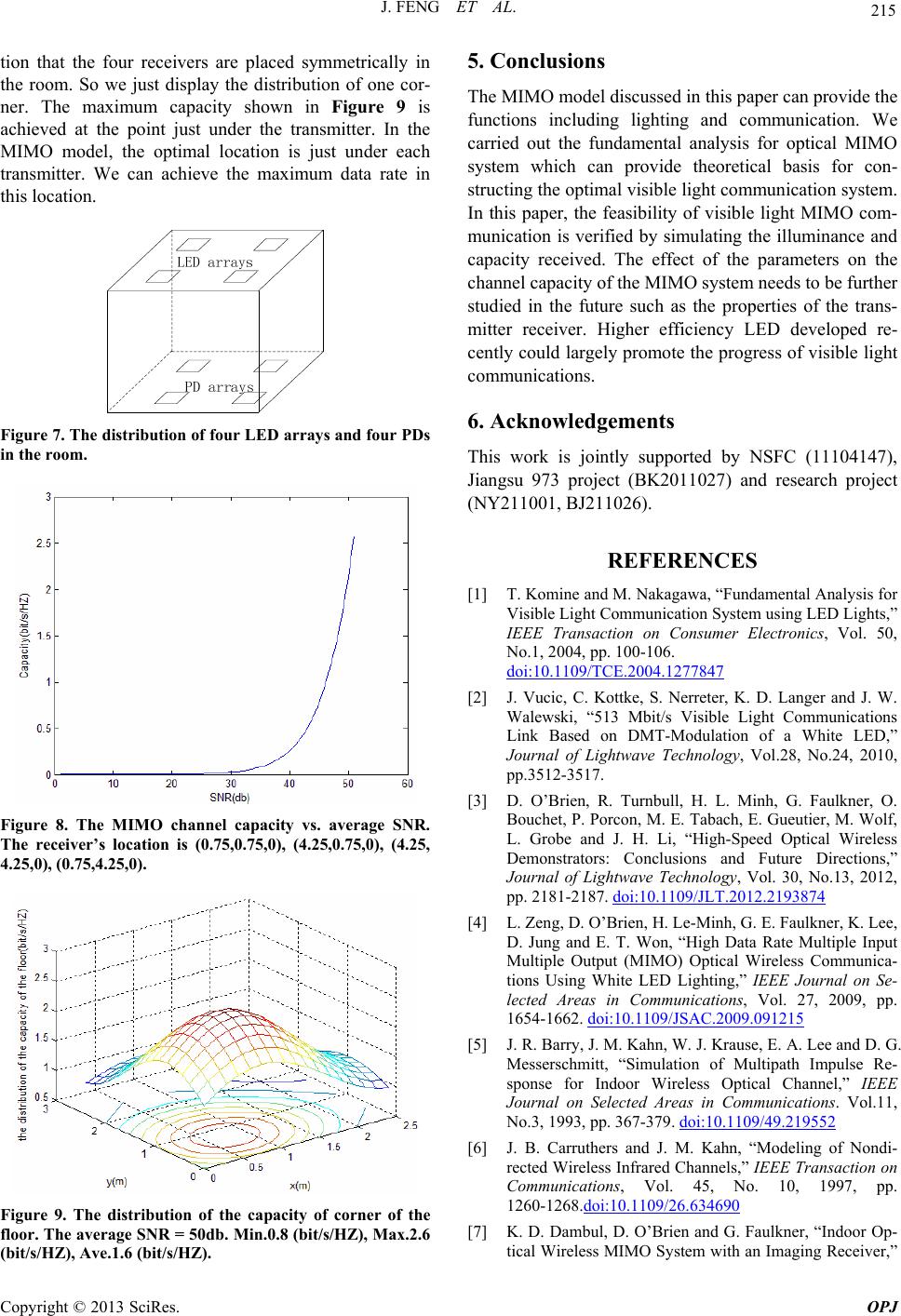
tion that the four receivers are placed symmetrically in
the room. So we just display the distribution of one cor-
ner. The maximum capacity shown in Figure 9 is
achieved at the point just under the transmitter. In the
MIMO model, the optimal location is just under each
transmitter. We can achieve the maximum data rate in
this location.
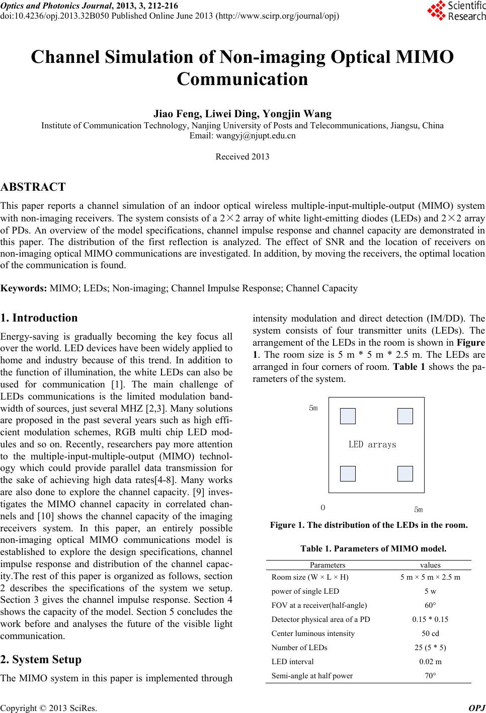
Figure 7. The distribution of four LED array s and four PDs
in the room.
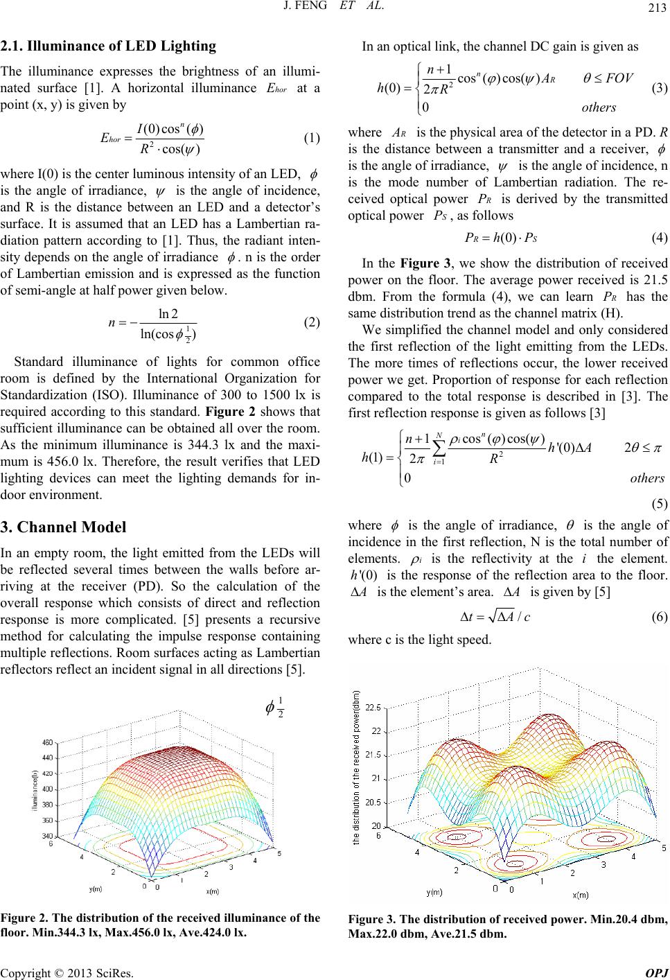
Figure 8. The MIMO channel capacity vs. average SNR.
The receiver’s location is (0.75,0.75,0), (4.25,0.75,0), (4.25,
4.25,0), (0.75,4.25,0).
Figure 9. The distribution of the capacity of corner of the
floor. The average SNR = 50db. Min.0.8 (bit/s/HZ), Max.2.6
(bit/s/HZ), Ave.1.6 (bit/s/HZ).
5. Conclusions
The MIMO model discussed in this paper can provide the
functions including lighting and communication. We
carried out the fundamental analysis for optical MIMO
system which can provide theoretical basis for con-
structing the optimal visible light communication system.
In this paper, the feasibility of visible light MIMO com-
munication is verified by simulating the illuminance and
capacity received. The effect of the parameters on the
channel capacity of the MIMO system needs to be further
studied in the future such as the properties of the trans-
mitter receiver. Higher efficiency LED developed re-
cently could largely promote the progress of visible light
communications.
6. Acknowledgements
This work is jointly supported by NSFC (11104147),
Jiangsu 973 project (BK2011027) and research project
(NY211001, BJ211026) .
REFERENCES
[1] T. Komine and M. Nakagawa, “Fundamental Analysis for
Visible Light Communication System using LED Lights,”
IEEE Transaction on Consumer Electronics, Vol. 50,
No.1, 2004, pp. 100-106.
doi:10.1109/TCE.2004.1277847
[2] J. Vucic, C. Kottke, S. Nerreter, K. D. Langer and J. W.
Walewski, “513 Mbit/s Visible Light Communications
Link Based on DMT-Modulation of a White LED,”
Journal of Lightwave Technology, Vol.28, No.24, 2010,
pp.3512-3517.
[3] D. O’Brien, R. Turnbull, H. L. Minh, G. Faulkner, O.
Bouchet, P. Porcon, M. E. Tabach, E. Gue utier, M. Wolf,
L. Grobe and J. H. Li, “High-Speed Optical Wireless
Demonstrators: Conclusions and Future Directions,”
Journal of Lightwave Technology, Vol. 30, No.13, 2012,
pp. 2181-2187. doi:10.1109/JLT.2012.2193874
[4] L. Zeng, D. O’Brien, H. Le-Minh, G. E. Faulkner, K. Lee,
D. Jung and E. T. Won, “High Data Rate Multiple Input
Multiple Output (MIMO) Optical Wireless Communica-
tions Using White LED Lighting,” IEEE Journal on Se-
lected Areas in Communications, Vol. 27, 2009, pp.
1654-1662. doi:10.1109/JSAC.2009.091215
[5] J. R. Barry, J. M. Ka hn, W. J. Krau se, E. A. Lee and D. G.
Messerschmitt, “Simulation of Multipath Impulse Re-
sponse for Indoor Wireless Optical Channel,” IEEE
Journal on Selected Areas in Communications. Vol.11,
No.3, 1993, pp. 367-379. doi:10.1109/49.219552
[6] J. B. Carruthers and J. M. Kahn, “Modeling of Nondi-
rected Wireless Infrared Channels,” IEEE Transaction on
Communications, Vol. 45, No. 10, 1997, pp.
1260-1268.doi:10.1109/26.634690
[7] K. D. Dambul, D. O’Brien and G. Faulkner, “Indoor Op-
tical Wireless MIMO System with an Imaging Receiver,”
Copyright © 2013 SciRes. OPJ
J. FENG ET AL.
Copyright © 2013 SciRes. OPJ
216
IEEE Photonics Technology Letters, Vol. 23, No. 2, 2011,
pp. 97-99. doi:10.1109/LPT.2010.2091627
[8] Y. A. Alqudah and M. Kavehrad, “MIMO Characteriza-
tion of Indoor Wireless Optocal Link Using a Dif-
fuse-Transmission Configuration,” IEEE Transaction on
Communications, Vol. 51, No. 9, 2003, pp. 1554-1560.
doi:10.1109/TCOMM.2003.816945
[9] S. L. Loyka, “Channel Capacity of MIMO Architecture
Using the Exponential Correlation Matrix,” IEEE Com-
munications Letters, Vol. 5, No. 9, 2001, pp. 369-371.
doi:10.1109/4234.951380
[10] X. Zhang, K. Y. C, H. Zhang and Z. Xu, “Capacity of
MIMO Visible Light Communication Channels,” IEEE,
WB3.4 (Contributed Oral), 2012, pp. 159-160.