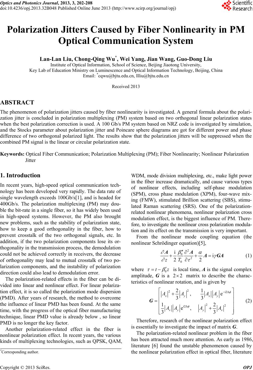
 Optics and Photonics Journal, 2013, 3, 202-208 doi:10.4236/opj.2013.32B048 Published Online June 2013 (http://www.scirp.org/journal/opj) Polarization Jitters Caused by Fiber Nonlinearity in PM Optical Communication System Lan-Lan Liu, Chong-Qing Wu*, Wei Yang, Jian Wang, Guo-Dong Liu Institute of Optical Information, School of Science, Beijing Jiaotong University, Key Lab of Education Ministry on Luminescence and Optical Information Technology, Beijing, China Email: *cqwu@bjtu.edu.cn, llliu@bjtu.edu.cn Received 2013 ABSTRACT The phenomenon of polarization jitters caused by fiber nonlinearity is investigated. A general formula about the polari- zation jitter is concluded in polarization multiplexing (PM) system based on two orthogonal linear polarization states when the best polarization correction is used. A 100 Gb/s PM system based on NRZ code is investigated by simulation, and the Stocks parameter about polarization jitter and Poincare sphere diagrams are got for different power and phase difference of two orthogonal polarized light. The results show that the polarization jitters will be suppressed when the combined PM signal is the linear or circular polarization state. Keywords: Optical Fiber Communication; Polarization Multiplexing (PM); Fiber Nonlinearity; Nonlinear Polarization Jitter 1. Introduction In recent years, high-speed optical communication tech- nology has been developed very rapidly. The data rate of single wavelength exceeds 100Gb/s[1], and is headed for 400Gb/s. The polarization multiplexing (PM) may dou- ble the bit-rate in a single fiber, so it has widely been used in high-speed systems. However, the PM also brought new problems, such as the stability of polarization state, how to keep a good orthogonality in the fiber, how to prevent crosstalk of the two orthogonal signals, etc. In addition, if the two polarization components lose its or- thogonality in the transmission process, the demodulation could not be achieved correctly in receivers, the decrease of orthogonality may lead to mutual crosstalk of two po- larization components, and the instability of polarization direction could also lead to demodulation error. Copyright © 2013 SciRes. OPJ The polarization-related effects in the fiber can be di- vided into linear and nonlinear effect. For linear polariza- tion effect, it is so called the polarization mode dispersion (PMD). After years of research, the method to overcome the influence of linear PMD has been found. At the same time, with the progress of the optical fiber manufacturing technique, linear PMD value is already below , so linear PMD is no longer the key factor . Another polarization-related effect in the fiber is nonlinear polarization effect. In recent years, the various kinds of multiplexing technologies, such as QPSK, QAM, WDM, mode division multiplexing, etc., make light power in the fiber increase dramatically, and cause various types of nonlinear effects, including self-phase modulation (SPM), cross phase modulation (XPM), four-wave mix- ing (FMW), stimulated Brillion scattering (SBS), stimu- lated Raman scattering (SRS). One of the polarization- related nonlinear phenomena, nonlinear polarization cross modulation effect, is the biggest influence of PM. There- fore, to investigate the nonlinear cross polarization modula- tion and its effect on the transmission is very important. From the nonlinear mode coupling equation (the nonlinear Schrödinger equation)[5], 2 02 0 ii 22zT AA AGA z (1) where 0 t is local ti me, A is the sign al complex amplitude, G is a 22 matrix to describe the charac- teristics of nonlinear rotation, and is given by 2 2i2 22 i2 21 , e 33 12 e, 33 xy xy xyy x AA AA AAA A G (2) Therefore, research of the nonlinear polarization effect is essentially to investigate the impact of matrix G. The polarization-related nonlinear problem in the fiber has been attracted much more attention. As early as 1986, literature [6] found the unstable phenomenon caused by the nonlinear polarization effect in optical fiber, literature *Corresponding author. 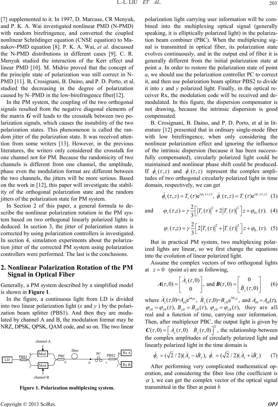 L.-L. LIU ET AL. 203 [7] supplemented to it. In 1997, D. Marcuse, CR Menyuk, and P. K. A. Wai investigated nonlinear PMD (N-PMD) with random birefringence, and converted the coupled nonlinear Schrödinger equation (CNSE equation) to Ma- nakov-PMD equation [8]. P. K. A. Wai, et al. discussed the N-PMD distributions in different cases [9]. C. R. Menyuk studied the interaction of the Kerr effect and linear PMD [10]. M. Midrio proved that the concept of the principle state of polarization was still correct in N- PMD [11]. B, Crosignani, B. Daino, and P. D. Porto, et al. studied the decreasing in the degree of polarization caused by N–PMD in the low-birefringence fiber[12]. In the PM system, the coupling of the two orthogonal signals resulted from the negative diagonal elements of the matrix G will leads to the crosstalk between two po- larization signals, which causes the instability of the two polarization states. This phenomenon is called the ran- dom jitter of the polarization state. It was received atten- tion from some writers [13]. However, in the previous literatures, the writers only considered the crosstalk for one channel not fo r PM. Because the randomicity of two channels is different from one channel, the amplitude, phase even the modulation format are different between the two channels, the jitters will be more serious. Based on the work in [12], this paper will inve stigate the stabil- ity of the orthogonal polarization state and the random jitters of the polarization state for PM system. In Section 2 of this paper, a general formula to de- scribe the nonlinear polarization rotation in the PM sys- tem based on two orthogonal linearly polarized lights is deduced. In section 3, the jitter of polarization states is corrected by using polarization controllers is investigated. In section 4, simulation experiments about the polariza- tion jitter of the corrected PM system using polarization controllers were performed. The last is the conclusions. Copyright © 2013 SciRes. OPJ 2. Nonlinear Polarization Rotation of the PM Signal in Optical Fiber Generally, a PM system described by a simplified model is shown in Figure 1. In the figure, a continuous light from LD is divided into two linear polarization lig ht (x and y ) by the polari- zation beam splitter (PBS1). And then they are modu- lated by channel A and B, the modulation format may be NRZ, DPSK, QPSK, QAM code, and so on. The two linear Rx A Rx B LD Mod Mod channel A channel B PBS1 PBC fiber PC PBS2 a c b Figure 1. Polarization multiplexing system. polarization light carrying user information will be com- bined into the multiplexing optical signal (generally speaking, it is elliptically po larized light) in the polariza- tion beam combiner (PBC). When the multiplexing sig- nal is transmitted in optical fiber, its polarization state evolves continuously, and in the output end of fiber it is generally different from the initial polarization state at point a. In order to restore the polarization state of point a, we should use the polarization controller PC to correct it, and then use polarization beam splitter PBS2 to divide it into x and y polarized light. Finally, in the optical re- ceiver Rx, the modulation code will be received and de- modulated. In this figure, the dispersion compensator is not drawing, because the intrinsic dispersion is good compensated. B. Crosignani, B. Daino, and P. D. Porto, et al in lit- erature [12] presented that in ordinary single-mode fiber with low birefringence, when only considering the nonlinear polarization effect and ignoring the influence of the intrinsic dispersion (because it has been success- fully compensated), circularly polarized light could be maintained and nonlinear phase shift could be produced. If (,)z and (,)z represent the complex ampli- tudes of two ortho gonal circularly polarized light in time domain, respectively, we can get i (,)i (,) (,)()e, (,)()e z zT zT (3) and 22 0 2 (,)()2 ()(). 3 zT Tz (4) 22 0 2 (,)2 ()()(). 3 zTTz (5) But in practical PM system, two multiplexing polar- ized lights are linear, so we first change the equations into the evolution of linear polarized light. Assume the complex vectors of two orthogonal lights at 0z (point a) are as following, 0 (,0) (,0), and (,0)(,0) 0 x y A B AB (6) where and 00 0 i 0 (,0)= e, x xx AA 0 i 0 (,0)= e , y yy BB (), xx AA 00 0000xxy yyy (), ()BB, (), they are all real and a function of time, carrying user information. Then, after multiplexer PBC, the output light is given by T (,0)(,0) (,0) xy AB C, the relationship between the complex amplitudes of circularly polarized light and linearly polarized light in the time domain is (2/2)(i), (2/2)(i) yxy BA B (7) After performing very complicated mathematical op- eration, and considering the fiber loss (the coefficient is ), we can get the complex vector of the optical signal transmitted in the fiber at point b  L.-L. LIU ET AL. 204 22 00 i( )2 (,) (,0) cos sin e (,) (,0) sin cos xy z zA A xx yy Cz A Cz B Copyright © 2013 SciRes. OPJ (8) where eff (1e)/ z z ( )(2/3) is the fiber nonlinear effective length, and eff 0 00 sin xy zAB . From formula (8), we can see that due to the nonlinear polarization effect, the polarization rotation will occur, but the orthogonality of two signals can still be maintained. The rotating angle () is related to the fiber nonlinear coefficient , nonlinear effective length , amplitudes of two multiplexing signals 0 eff z () x A and 0(), y B phase difference 0, and etc. Because 0x()A and 0() y B are all random variable, polarization will jitter. 3. Polarization Jitters after Polarization State Correction As stated above, in order to perform polarization demul- tiplexing correctly, we must correct the polarization state using a polarization controller (see Figure 1). Compared with the speed of change of the modulation signal, the adjusting speed of the polarization controller is very low, so only the low order correction can be realized. We only consider the mean value correction, it means that the polarization controller only corrects the mean value of the nonlinear polarization rotation angle. Assume the corrective angle produced by the polariza- tion controller is , which should be the mean value of the nonlinear rotation angle () , i.e. eff 000 0 2 ()() ()sin()d 3 T xy zAB T (9) where T is the action time. So, the compensation matrix of PC is given by PC cos sin sin cos U (10) It is not difficult to find out the polarization state of corrected light at point c is 22 00 i( )2PC (,) (,0) cos sin e (,) (,0) sin cos xy z zA B x y Cz A Cz B Ux y (11) To substitute formula (10) into (11), we can get 22 00 i( )2 (,) (,0) cos sin e (,) (,0) sin cos xy z zA B x y Cz A Cz B x y (12) Generally, ()() 0 , the jitter of polari- zation state will be observed. From Equation. (12) we can get the instantaneous Stocks parameters 00 (,) e[()()] zAB szP P 10 00 (,)e{cos2[()()] 2sin2()()cos} zAB AB szP P PP 0 (14) 200 00 e{sin2()[ ()()] 2cos2()()()cos} zAB AB sPP PP 0 (15) 300 e2 ()()sin zAB sPP 0 (16) In Equation (13)-(16), the 0() A P and 0() B P are the initial power of channel A and B, respectively. In order to draw the Poincare sphere, we should normized Stocks parameters, which are described as following 0(,)1sz (17) 100 00 00 (,)[cos2[()()] 2sin2( )( )cos] [() ()] AB AB AB szP P PP PP (18) 200 00 00 (,)[sin2()[()()] 2cos2( )()( )cos] [() ()] AB AB AB szP P PP PP 0 (19) 00 300 2()()sin (,) [()()] AB AB PP sz PP 0 (20) 4. Simulation Experiment of the Polarization Jitters for NRZ Code Although NRZ code has rarely been used in high speed optical communication system, as a kind of basic modu- lation format, its research is still meaningful. The bit-rate of PM system is 100 Gb/s. For these high speed systems, we generally use a narrow linewidth laser smaller than 100 kHz with excellent coherence performance, and the coherence time is larger than 10s . So for a 100 Gb/s signal with 10ps pulse width, the phase difference 0 between two multiplexing signals can be thought of a constant in 1000 bits. The simulation is divided into two cases, one is the power of the two multiplexing signals are equal, all are 10 mw, so that the circular polarization state may appear; the other one is to assume the power of interferencing signal is two times of the interferenced signal, namely channel A is 10 mw, channel B is 20mw, so the circular polarization state does not exist. When simulating, the initial signal-to-noise ratio (SNR) of NRZ code is assumed to be 30 dB, which is a good signal. The optical fiber length is 50 km, and the loss is 0.2 dB/km, the effective nonlinear length is 19.54 km. Figure 2 shows 100 bit waveform (left) and eye diagram (right) of input signal (channel A). 4.1. Polarization Multiplexing with Equal Power 0 (13) In the first case, the power of the two multiplexing sig- 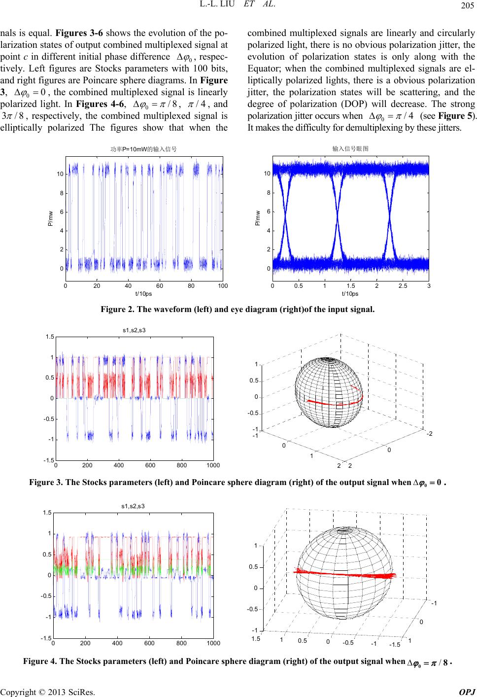 L.-L. LIU ET AL. Copyright © 2013 SciRes. OPJ 205 nals is equal. Figures 3-6 shows the evolu tion of the po- larization states of output combined multiplexed signal at point c in different initial phase difference 0 , respec- tively. Left figures are Stocks parameters with 100 bits, and right figures are Poincare sphere diagrams. In Figure 3, 00 , the combined multiplexed signal is linearly polarized light. In Figures 4-6, 0/8 , /4 , and 3/8 , respectively, the combined multiplexed signal is elliptically polarized The figures show that when the combined multiplexed signals are linearly and circularly polarized light, there is no obvious polarization jitter, the evolution of polarization states is only along with the Equator; when the combined multiplexed signals are el- liptically polarized lights, there is a obvious polarization jitter, the polarization states will be scattering, and the degree of polarization (DOP) will decrease. The strong polarization jitter occur s when 0/4 (see Figure 5). It makes the difficulty for demultiplexi ng by these jitters. 020 40 60 80100 0 2 4 6 8 10 t/10ps P/mw 功率P=10mW的输入信号 00.5 11.5 22.5 3 0 2 4 6 8 10 t/ 10ps P/mw 输入信号眼 图 Figure 2. The waveform (left) and eye diagram (right)of the input signal. 0200 400 600 8001000 -1.5 -1 -0.5 0 0.5 1 1.5 s1,s2,s 3 -2 0 2 -1 0 1 2 -1 -0.5 0 0.5 1 Figure 3. The Stocks parameters (left) and Poincare sphere diagram (right) of the output signal when00 . 0200 400600 8001000 -1.5 -1 -0.5 0 0.5 1 1.5 s1,s2,s3 -1.5 -1 -0.5 0 0.5 1 1.5 -1 0 1 -1 -0.5 0 0.5 1 Figure 4. The Stocks parameters (left) and Poincare sphere diagram (right) of the output signal when/08 . 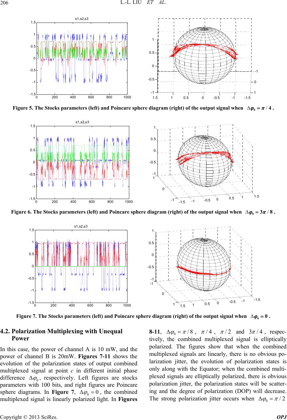 L.-L. LIU ET AL. 206 0200 400 600 800 1000 -1.5 -1 -0.5 0 0.5 1 1.5 s1,s2,s3 -1.5-1-0.500.511.5 -1 0 1 -1 -0.5 0 0.5 1 Figure 5. The Stocks parameters (left) and Poincare sphere diagram (right) of the output signal when . /04 0200 400 600 800 1000 -1.5 -1 -0.5 0 0.5 1 1.5 s1, s2,s3 -1.5 -1-0.500.5 11. 5 -1 0 1 -1 -0.5 0 0.5 1 Figure 6. The Stocks parameters (left) and Poincare sphere diagram (right) of the output signal when /038 . 0200 400 600 800 1000 -1.5 -1 -0.5 0 0.5 1 1.5 s1,s2,s 3 -1.5 -1 -0.5 0 0.5 1 1.5 -1 0 1 -1 -0.5 0 0.5 1 Figure 7. The Stocks parameters (left) and Poincare sphere diagram (right) of the output signal when 00 . 4.2. Polarization Multiplexing with Unequal Power In this case, the power of channel A is 10 mW, and the power of channel B is 20mW. Figures 7-11 shows the evolution of the polarization states of output combined multiplexed signal at point c in different initial phase difference 0 , respectively. Left figures are stocks parameters with 100 bits, and right figures are Poincare sphere diagrams. In Figure 7, 00 , the combined multiplexed signal is linearly polarized light. In Figures 8-11, 0/8 , /4 , /2 and 3/4 , respec- tively, the combined multiplexed signal is elliptically polarized. The figures show that when the combined multiplexed signals are linearly, there is no obvious po- larization jitter, the evolution of polarization states is only along with the Equator; when the combined multi- plexed signals are elliptically polarized, there is obvious polarization jitter, the polarization states will be scatter- ing and the degree of polarization (DOP) will decrease. The strong polarization jitter occurs when 0/2 Copyright © 2013 SciRes. OPJ 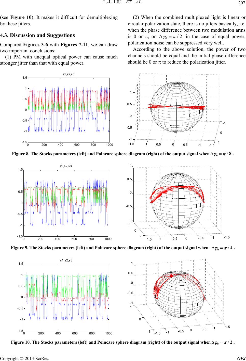 L.-L. LIU ET AL. 207 (see Figure 10). It makes it difficult for demultiplexing by these jitters. 4.3. Discussion and Suggestions Compared Figures 3-6 with Figures 7-11, we can draw two important conclusions: (1) PM with unequal optical power can cause much stronger jitter than that with equal power. (2) When the combined multiplexed light is linear or circular polarization state, there is no jitters basically, i.e. when the phase difference between two modulation arms is 0 or , or 0/2 in the case of equal power, polarization noise can be suppresse d very we ll. According to the above solution, the power of two channels should be equal and the initial phase difference shoul d b e 0 o r to reduce the polarization jitter. 0200 400 600 800100 -1.5 -1 -0.5 0 0.5 1 1.5 s1 ,s2,s3 -1.5-1 -0.5 0 0.5 1 1. 5 -1 0 1 -1 -0.5 0 0.5 1 Figure 8. The Stocks parameters (left) and Poincare sphere diagram (right) of the output signal when. /08 0200400600800 1000 -1.5 -1 -0.5 0 0.5 1 1.5 s1,s2,s3 -1.5 -1 -0.5 0 0.5 1 1.5 -1 0 1 -1 -0.5 0 0.5 1 Figure 9. The Stocks parameters (left) and Poincare sphere diagram (right) of the output signal when /04 . 0200400 600 8001000 -1.5 -1 -0.5 0 0.5 1 1.5 s1,s2,s3 -1.5 -1 -0.5 00.5 11.5 -1 0 1 -1 -0.5 0 0.5 1 Figure 10. The Stocks parameters (left) and Poincare sphere diagram (right) of the output signal when/02 . C opyright © 2013 SciRes. OPJ 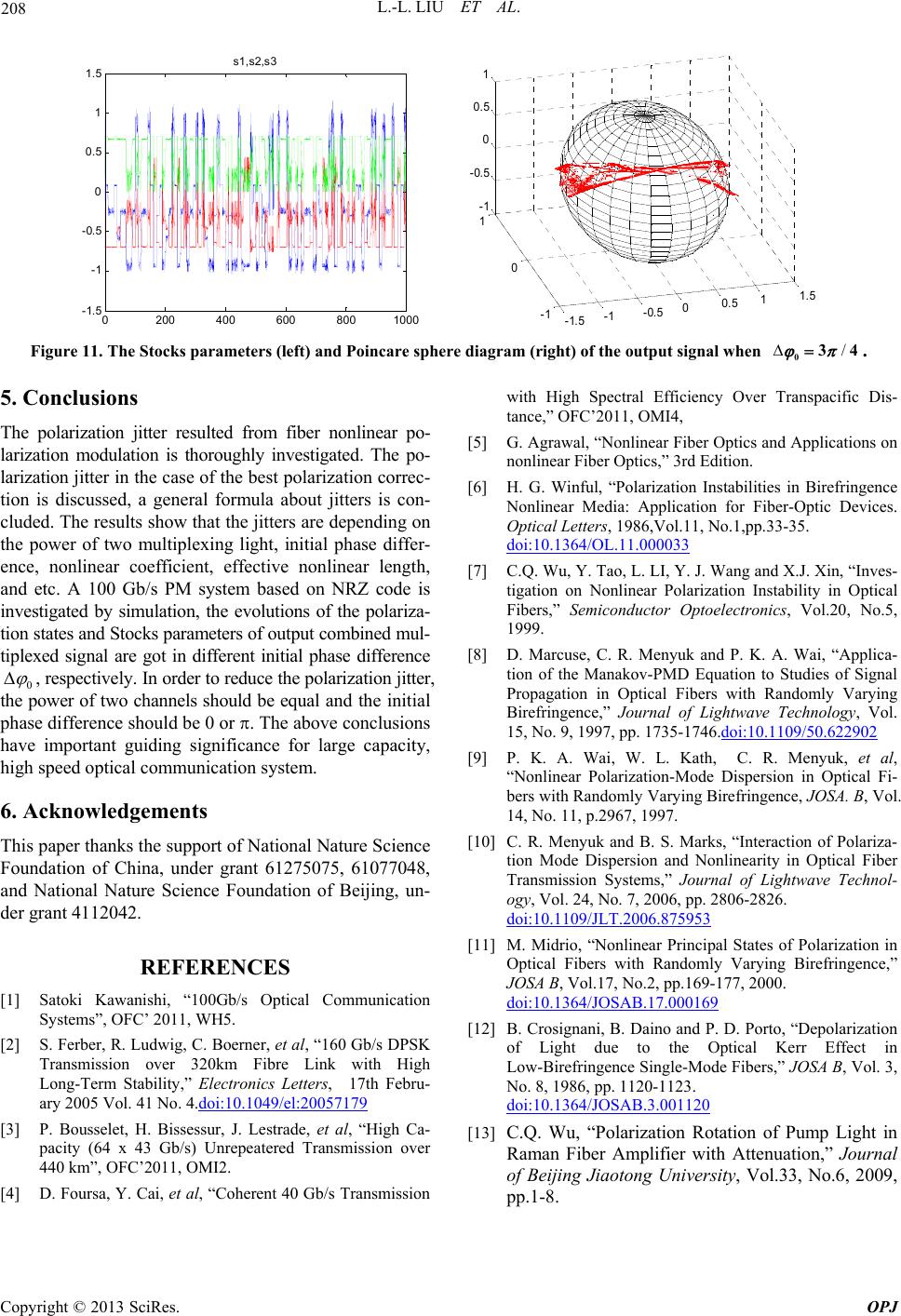 L.-L. LIU ET AL. 208 0200 400600800 1000 -1.5 -1 -0.5 0 0.5 1 1.5 s1, s2,s3 -1.5-1-0.500.5 11.5 -1 0 1 -1 -0.5 0 0.5 1 Figure 11. The Stocks parameters (left) and Poincare sphere diagram (right) of the output signal when . /034 5. Conclusions The polarization jitter resulted from fiber nonlinear po- larization modulation is thoroughly investigated. The po- larization jitter in the case of the best polarization correc- tion is discussed, a general formula about jitters is con- cluded. The results show that the jitters are depending on the power of two multiplexing light, initial phase differ- ence, nonlinear coefficient, effective nonlinear length, and etc. A 100 Gb/s PM system based on NRZ code is investigated by simulation, the evolutions of the polariza- tion states and Stocks parameters of output combined mul- tiplexed signal are got in different initial phase difference 0 , respectively. In order to reduce the polarization jitter, the power of two channels should be equal and the initial phase difference should be 0 or . The above conclusions have important guiding significance for large capacity, high speed optical communication system. 6. Acknowledgements This paper thanks the support of National Nature Science Foundation of China, under grant 61275075, 61077048, and National Nature Science Foundation of Beijing, un- der grant 4112042. REFERENCES [1] Satoki Kawanishi, “100Gb/s Optical Communication Systems”, OFC’ 2011, WH5. [2] S. Ferber, R. Ludwig, C. Boerner, et al, “160 Gb/s DPSK Transmission over 320km Fibre Link with High Long-Term Stability,” Electronics Letters, 17th Febru- ary 2005 Vol. 41 No. 4.doi:10.1049/el:20057179 [3] P. Bousselet, H. Bissessur, J. Lestrade, et al, “High Ca- pacity (64 x 43 Gb/s) Unrepeatered Transmission over 440 km”, OFC’2011, OMI2. [4] D. Foursa, Y. Cai, et al, “Coherent 40 Gb/s Transmission with High Spectral Efficiency Over Transpacific Dis- tance,” OFC’2011, OMI4, [5] G. Agrawal, “Nonlinear Fiber Optics and Applications on nonlinear Fiber Optics,” 3rd Edition. [6] H. G. Winful, “Polarization Instabilities in Birefringence Nonlinear Media: Application for Fiber-Optic Devices. Optical Letters, 1986,Vol.11, No.1,pp.33-35. doi:10.1364/OL.11.000033 [7] C.Q. Wu, Y. Tao, L. LI, Y. J. Wang and X.J. Xin, “Inves- tigation on Nonlinear Polarization Instability in Optical Fibers,” Semiconductor Optoelectronics, Vol.20, No.5, 1999. [8] D. Marcuse, C. R. Menyuk and P. K. A. Wai, “Applica- tion of the Manakov-PMD Equation to Studies of Signal Propagation in Optical Fibers with Randomly Varying Birefringence,” Journal of Lightwave Technology, Vol. 15, No. 9, 1997, pp. 1735-1746.doi:10.1109/50.622902 [9] P. K. A. Wai, W. L. Kath, C. R. Menyuk, et al, “Nonlinear Polarization-Mode Dispersion in Optical Fi- bers with Randomly Varying Birefringence, JOSA. B, Vol. 14, No. 11, p.2967, 1997. [10] C. R. Menyuk and B. S. Marks, “Interaction of Polariza- tion Mode Dispersion and Nonlinearity in Optical Fiber Transmission Systems,” Journal of Lightwave Technol- ogy, Vol. 24, No. 7, 2006, pp. 2806-2826. doi:10.1109/JLT.2006.875953 [11] M. Midrio, “Nonlinear Principal States of Polarization in Optical Fibers with Randomly Varying Birefringence,” JOSA B, Vol.17, No.2, pp.169-177, 2000. doi:10.1364/JOSAB.17.000169 [12] B. Crosignani, B. Daino and P. D. Porto, “Depolarization of Light due to the Optical Kerr Effect in Low-Birefringence Single-Mode Fibers,” JOSA B, Vol. 3, No. 8, 1986, pp. 1120-1123. doi:10.1364/JOSAB.3.001120 [13] C.Q. Wu, “Polarization Rotation of Pump Light in Raman Fiber Amplifier with Attenuation,” Journal of Beijing Jiaotong University, Vol.33, No.6, 2009, pp.1-8. Copyright © 2013 SciRes. OPJ
|