Z.-Y. WANG ET AL.
194
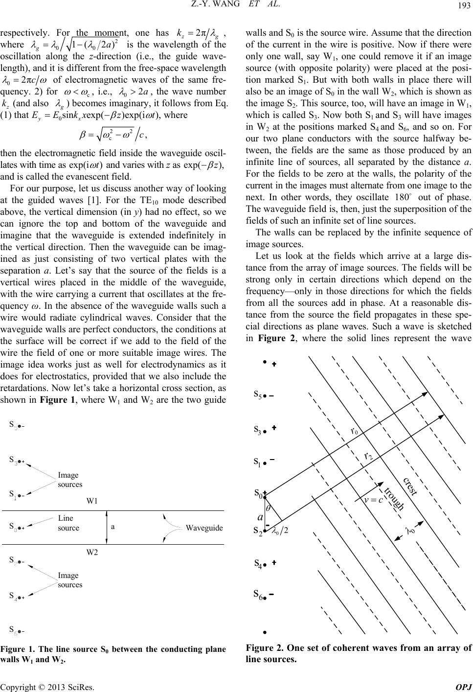
crests and dashed lines represent the troughs. The wave
direction will be the one for which the difference in the
retardation for two neighboring sources to the crest of a
wave corresponds to one-half a period of oscillation. In
other words, the difference between r2 and r0 in the fig-
ure is one-half of the free-space wavelength: 20
rr
02
. The angle θ in then given by 0
sin 2a
.
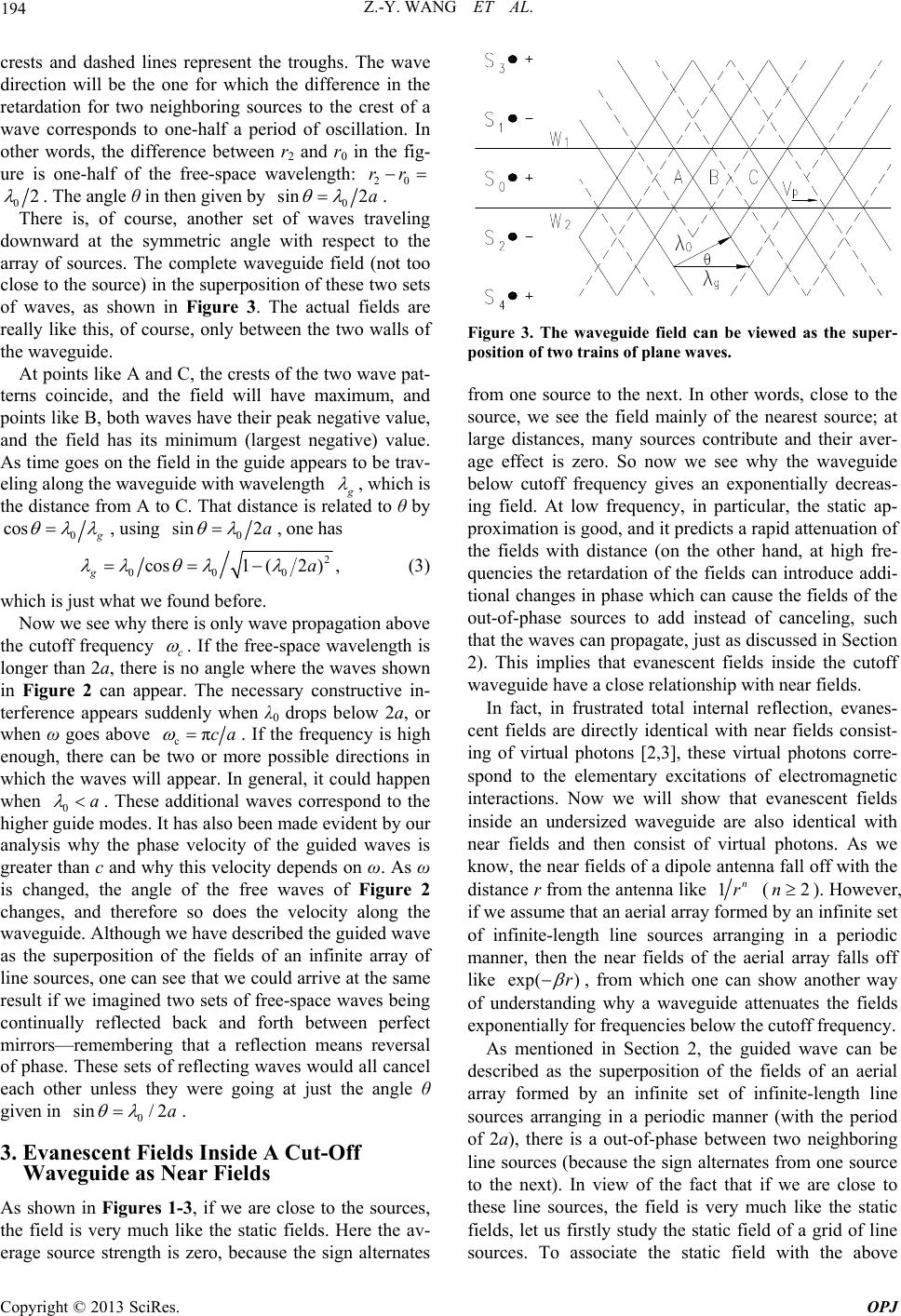
There is, of course, another set of waves traveling
downward at the symmetric angle with respect to the
array of sources. The complete waveguide field (not too
close to the source) in the superposition of these two sets
of waves, as shown in Figure 3. The actual fields are
really like this, of course, only between the two walls of
the waveguide.
At points like A and C, the crests of the two wave pat-
terns coincide, and the field will have maximum, and
points like B, both waves have their peak negative value,
and the field has its minimum (largest negative) value.
As time goes on the field in the guide appears to be trav-
eling along the waveguide with wavelength
, which is
the distance from A to C. That distance is related to θ by
0
cos
, using 0
sin 2a
, one has
2
000
cos1(2 ),
ga
(3)
which is just what we found before.
Now we see why there is only wave propagation above
the cutoff frequency c
. If the free-space wavelength is
longer than 2a, there is no angle where the waves shown
in Figure 2 can appear. The necessary constructive in-
terference appears suddenly when λ0 drops below 2a, or
when ω goes above cπca
. If the frequency is high
enough, there can be two or more possible directions in
which the waves will appear. In general, it could happen
when 0a
sin
. These additional waves correspond to the
higher guide modes. It has also been made evident by our
analysis why the phase velocity of the guided waves is
greater than c and why this velocity depends on ω. As ω
is changed, the angle of the free waves of Figure 2
changes, and therefore so does the velocity along the
waveguide. Although we have described the guided wave
as the superposition of the fields of an infinite array of
line sources, one can see that we could arrive at the same
result if we imagined two sets of free-space waves being
continually reflected back and forth between perfect
mirrors—remembering that a reflection means reversal
of phase. These sets of reflecting waves would all cancel
each other unless they were going at just the angle θ
given in 0/ 2a
.
3. Evanescent Fields Inside A Cut-Off
Waveguide as Near Fields
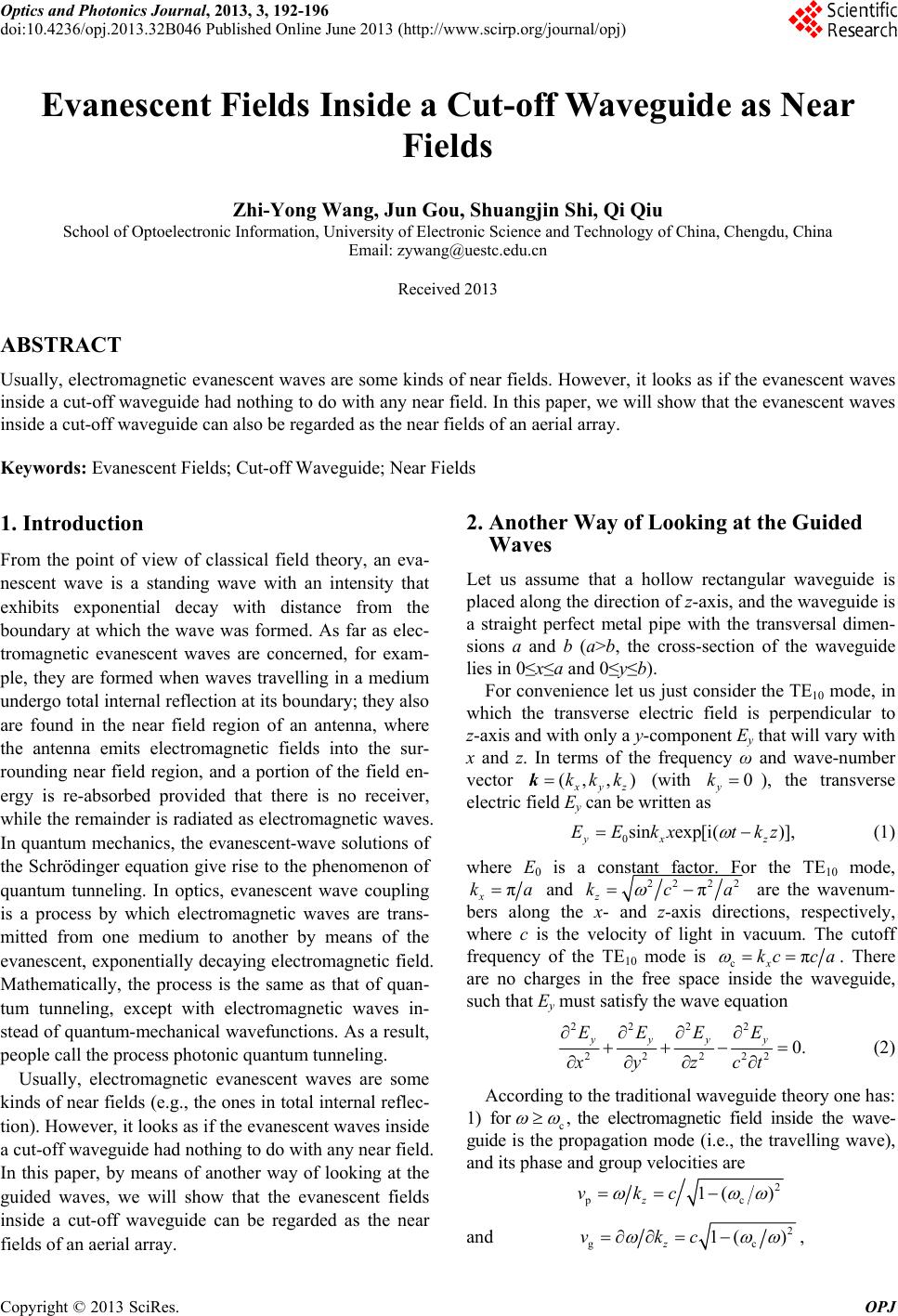
As shown in Figures 1-3, if we are close to the sources,
the field is very much like the static fields. Here the av-
erage source strength is zero, because the sign alternates
Figure 3. The waveguide field can be viewed as the super-
position of two trains of plane waves.
from one source to the next. In other words, close to the
source, we see the field mainly of the nearest source; at
large distances, many sources contribute and their aver-
age effect is zero. So now we see why the waveguide
below cutoff frequency gives an exponentially decreas-
ing field. At low frequency, in particular, the static ap-
proximation is good, and it predicts a rapid attenuation of
the fields with distance (on the other hand, at high fre-
quencies the retardation of the fields can introduce addi-
tional changes in phase which can cause the fields of the
out-of-phase sources to add instead of canceling, such
that the waves can propagate, just as discussed in Section
2). This implies that evanescent fields inside the cutoff
waveguide have a close relationship with near fields.
In fact, in frustrated total internal reflection, evanes-
cent fields are directly identical with near fields consist-
ing of virtual photons [2,3], these virtual photons corre-
spond to the elementary excitations of electromagnetic
interactions. Now we will show that evanescent fields
inside an undersized waveguide are also identical with
near fields and then consist of virtual photons. As we
know, the near fields of a dipole antenna fall off with the
distance r from the antenna like 1n
r (). However,
if we assume that an aerial array formed by an infinite set
of infinite-length line sources arranging in a periodic
manner, then the near fields of the aerial array falls off
like
2n
exp( )r
, from which one can show another way
of understanding why a waveguide attenuates the fields
exponentially for frequencies below the cutoff frequency.
As mentioned in Section 2, the guided wave can be
described as the superposition of the fields of an aerial
array formed by an infinite set of infinite-length line
sources arranging in a periodic manner (with the period
of 2a), there is a out-of-phase between two neighboring
line sources (because the sign alternates from one source
to the next). In view of the fact that if we are close to
these line sources, the field is very much like the static
fields, let us firstly study the static field of a grid of line
sources. To associate the static field with the above
Copyright © 2013 SciRes. OPJ