Paper Menu >>
Journal Menu >>
 Optics and Photonics Journal, 2013, 3, 153-157 doi:10.4236/opj.2013.32B037 Published Online June 2013 (http://www.scirp.org/journal/opj) Real-time Audio & Video Transmission System Based on Visible Light Communication Yingjie He, Liwei Ding, Yuxian Gong, Yongjin Wang* Institute of Communication Technology, Nanjing University of Posts and Telecommunications, Nanjing, China Email: *wangyj@njupt.edu.com Received 2013 ABSTRACT With the increasing popularity of solid sate lighting devices, Visible Light Communication (VLC) is globally recog- nized as an advanced and promising technology to realize short-range, high speed as well as large capacity wireless data transmission. In this paper, we propose a prototype of real-time audio and video broadcast system using inexpensive commercially available light emitting diode (LED) lamps. Experimental results show that real-time high quality audio and video with the maximum distance of 3 m can be achieved through proper layout of LED sources and improvement of concentration effects. Lighting model within room environment is designed and simulated which indicates close rela- tionship between layou t of light sources and distributio n of illuminance. Keywords: Visible Light Communications; LED; Real-Time Video and Audio Broadcast System; Light Source Arrangement; Illuminance Distribution 1. Introduction Visible Light Communication (VLC) was first proposed in 2004 by Toshihiki Komine and has progressed rapidly ever since with the development of solid state light sources, especially light emitting diodes (LEDs) [1]. The great popularity of VLC owes largely to the advantages of LED such as high brightness, low cost, small size, low power consumption, long lifetime and low heat radiation. VLC explores the unregulated visible light portion of the electromagnetic spectrum and acts as a supplement rather than substitute of established RF systems. With comple- mentary strengths of both technologies, excess capacity demands of RF channels can be off-loaded to VLC net- works, which enable users to seamlessly access to the Internet while keeping high Qos levels and avoiding net- work congestions and delays. The con cept of a fulldu plex multi-access system for LED-based wireless communi- cations is proposed by Nakagawa laboratories [1]. Sim- plex and duplex transceiver prototypes have been dem- onstrated in [2] which also prove the effectiveness of replacing existing illumination systems with LED light- ing devices. With 300 THz of bandwidth available for VLC, multi- gigabit-per-second data rates could be pro- vided over short distances, for example, using array of LEDs in a multiple-input multiple-output (MIMO) sys- tem [3,4]. Besides wireless connectivity in home envi- ronment, combining the function of illumination and transmission is also attractive in specific scenarios where healthy, secured and non-interfered communication is necessary, such as hospital, underground mine, under- water, airplane, etc. In this paper, we develop a VLC prototype with large increase in transmission distance and improvement in channel capacity. The optical link which performs as the substitute of connector wire can be widely applied in video conference, real-time video frequency monitoring, smart traffic system and various practical scenarios where illumination and data transmission is in joint de- mand to serve modern daily life. MATLAB program is used to simulate the illuminance distribution for two practical light source deploy ments. The rest of the paper is organized as follows: In sec- tion 2, a prototype of the VLC real-time video/audio transmission system is presented. The experimental result is shown and analyzed in section 3. Section 4 illustrates the correlation between light source layout and illumi- nance distribution based on MATLAB simulation within a model room. Finally, Section 5 concludes the article. 2. VLC System Description Figure 1 shows the block diagram of the real-time video and audio broadcast system, which consists of a VLC wireless LOS link with two optical channels. VLC is free space optical communication, and line of sight (LOS) is the common link between two points in optical wireless communication system, where the trans- *Corresponding author. Copyright © 2013 SciRes. OPJ 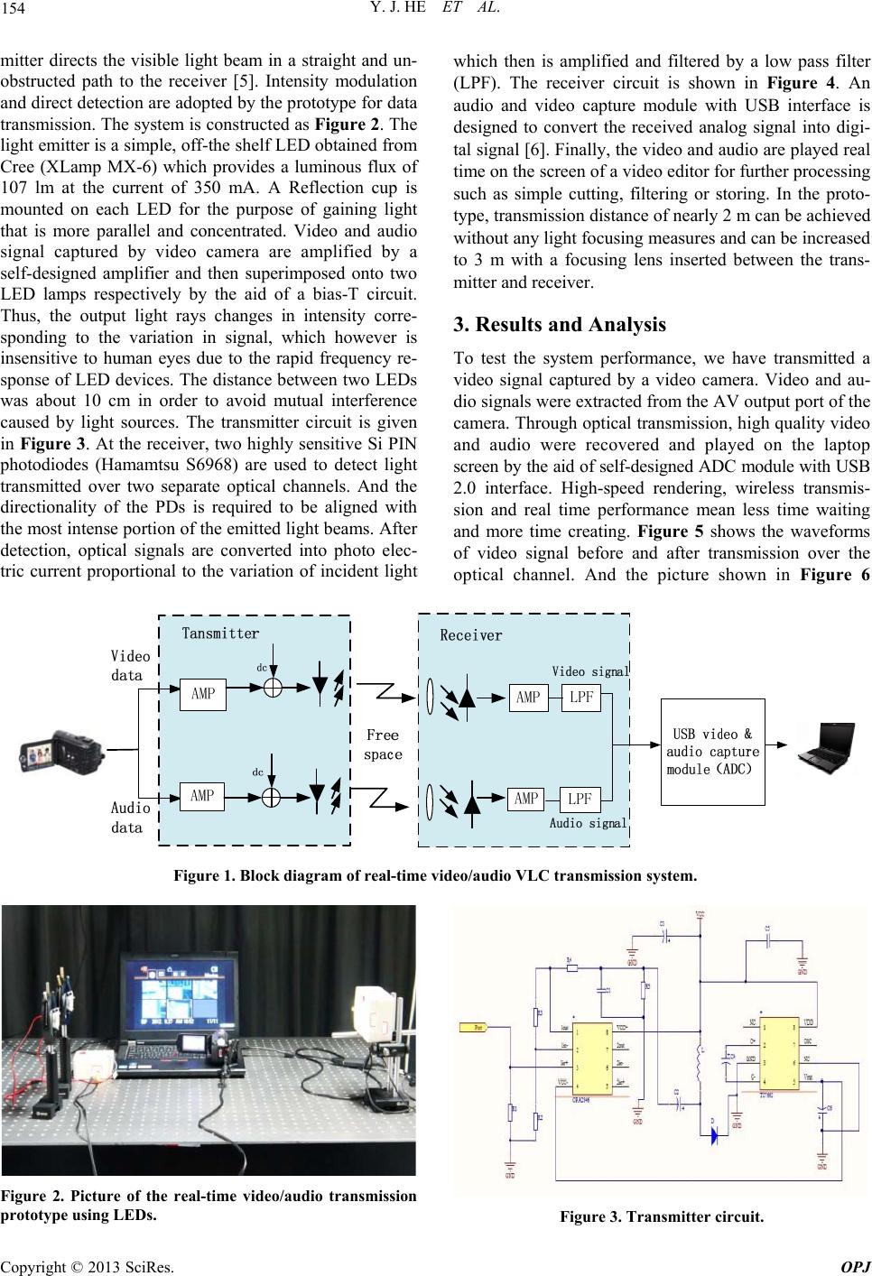 Y. J. HE ET AL. 154 mitter directs the visible light beam in a straight and un- obstructed path to the receiver [5]. Intensity modulation and direct detection are adopted by the prototype for data transmission. The system is constructed as Figure 2. The light emitter is a simple, off-the shelf LED obtained from Cree (XLamp MX-6) which provides a luminous flux of 107 lm at the current of 350 mA. A Reflection cup is mounted on each LED for the purpose of gaining light that is more parallel and concentrated. Video and audio signal captured by video camera are amplified by a self-designed amplifier and then superimposed onto two LED lamps respectively by the aid of a bias-T circuit. Thus, the output light rays changes in intensity corre- sponding to the variation in signal, which however is insensitive to human eyes due to the rapid frequency re- sponse of LED devices. The distance between two LEDs was about 10 cm in order to avoid mutual interference caused by light sources. The transmitter circuit is given in Figure 3. At the receiver, two highly sensitive Si PIN photodiodes (Hamamtsu S6968) are used to detect light transmitted over two separate optical channels. And the directionality of the PDs is required to be aligned with the most intense portion of the emitted light beams. After detection, optical signals are converted into photo elec- tric current proportional to the variation of incident light which then is amplified and filtered by a low pass filter (LPF). The receiver circuit is shown in Figure 4. An audio and video capture module with USB interface is designed to convert the received analog signal into digi- tal signal [6]. Finally, the video and audio are played real time on the screen of a video editor for further processing such as simple cutting, filtering or storing. In the proto- type, transmission distance of nearly 2 m can be achieved without an y ligh t fo cu s ing mea s u res an d c an be in cr ea s ed to 3 m with a focusing lens inserted between the trans- mitter and receiver. 3. Results and Analysis To test the system performance, we have transmitted a video signal captured by a video camera. Video and au- dio signals were extracted from the AV output port of the camera. Through optical transmission , high quality video and audio were recovered and played on the laptop screen by the aid of self-designed ADC module with USB 2.0 interface. High-speed rendering, wireless transmis- sion and real time performance mean less time waiting and more time creating. Figure 5 shows the waveforms of video signal before and after transmission over the optical channel. And the picture shown in Figure 6 Figure 1. Block diagram of real-time video/audio VLC transmission system. Figure 2. Picture of the real-time video/audio transmission prototype using LEDs. Figure 3. Transmitter circuit. Copyright © 2013 SciRes. OPJ 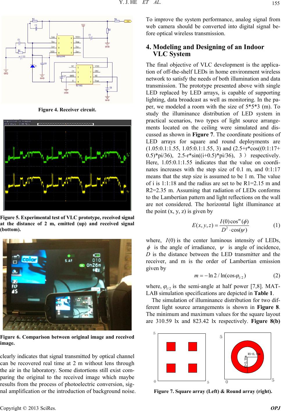 Y. J. HE ET AL. 155 Figure 4. Receiver circuit. Figure 5. Experimental test of VLC prototype, received signal at the distance of 2 m, emitted (up) and received signal (bottom). Figure 6. Comparison between original image and received image. clearly indicates that signal transmitted by optical channel can be recovered real time at 2 m without lens through the air in the laboratory. Some distortions still exist com- paring the original to the received image which maybe results from the process of photoelectric conversion, sig- nal amplification or the introduction of background noise. To improve the system performance, analog signal from web camera should be converted into digital signal be- fore optical wireless transmission. 4. Modeling and Designing of an Indoor VLC System The final objective of VLC development is the applica- tion of off-the-shelf LEDs in home environment wireless network to satisfy the need s of both illuminatio n and data transmission. The prototype presented above with single LED replaced by LED arrays, is capable of supporting lighting, data broadcast as well as monitoring. In the pa- per, we modeled a room with the size of 5*5*3 (m). To study the illuminance distribution of LED system in practical scenarios, two types of light source arrange- ments located on the ceiling were simulated and dis- cussed as shown in Figure 7. The coordinate positions of LED arrays for square and round deployments are (1.05:0.1:1.55, 1.05:0.1:1.55, 3) and (2.5+r*cos((0:1:17+ 0.5)*pi/36), 2.5-r*sin((i+0.5)*pi/36), 3)respectively. Here, 1.05:0.1:1.55 indicates that the value on coordi- nates increases with the step size of 0.1 m, and 0:1:17 means that the step size is assumed to be 1 m. The value of i is 1:1:18 and the radius are set to be R1=2.15 m and R2=2.35 m. Assuming that radiation of LEDs conforms to the Lambertian pattern and light reflection s on the wall are not considered. The horizontal light illuminance at the point (x, y, z) is given by 2 (0)cos( ) (,,) cos( ) m I Exyz D (1) where, (0) I is the center luminous intensity of LEDs, is the angle of irradiance, is angle of incidence, D is the distance between the LED transmitter and the receiver, and m is the order of Lambertian emission given by 1/2 ln 2 / ln(cos)m (2) where, 1/2 is the semi-angle at half power [7,8]. MAT- LAB simulation specifications are depicted in Table 1 . The simulation of illuminance distribution for two dif- ferent light source arrangements is shown in Figure 8. Th e mi n i mu m a n d ma x i mum v a l u es fo r th e s q u ar e la y ou t are 310.59 lx and 823.42 lx respectively. Figure 8(b) Figure 7. Square array (Left) & Round array (right). Copyright © 2013 SciRes. OPJ 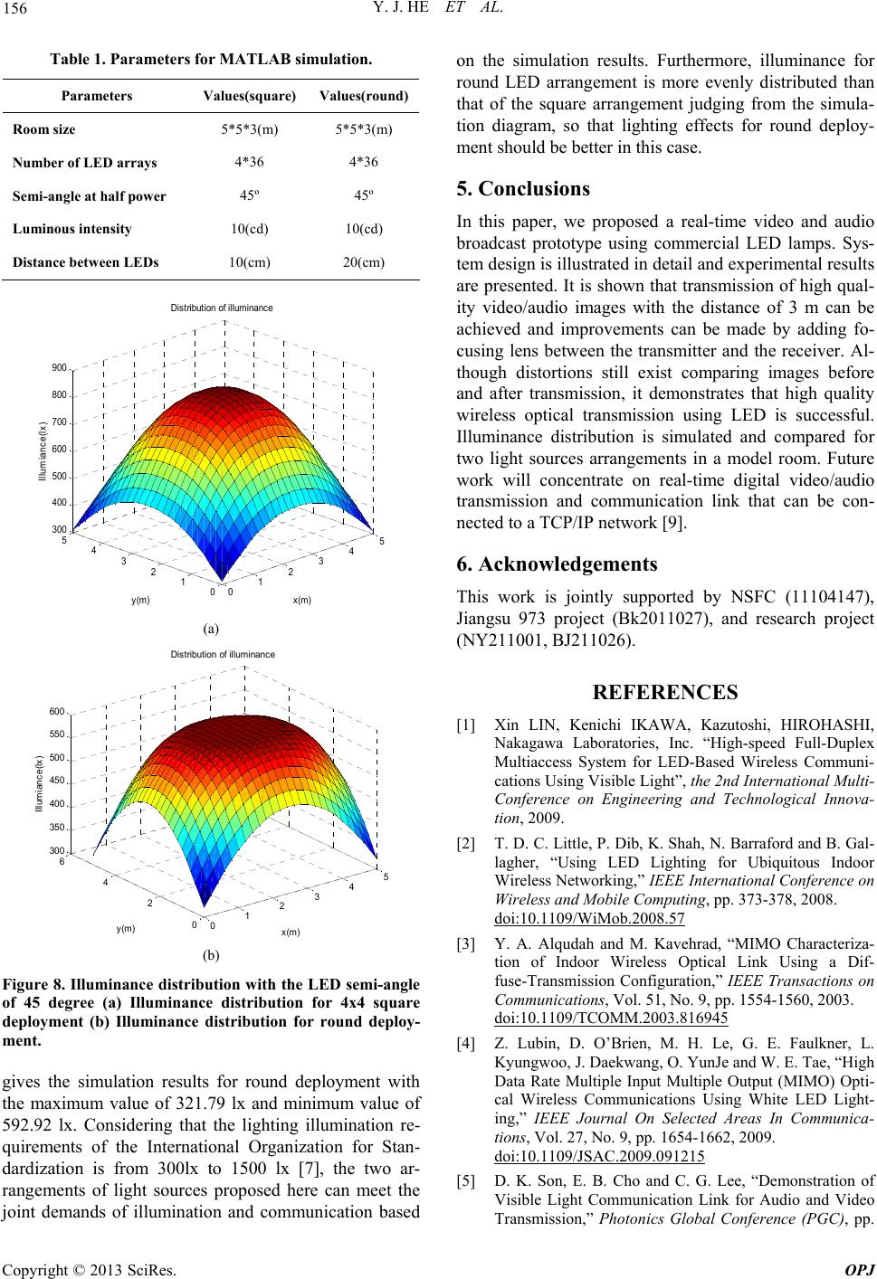 Y. J. HE ET AL. 156 Table 1. Parameters for MATLAB simulation. Parameters Values(square) Values(round) Room size 5*5*3(m) 5*5*3(m) Number of LED arrays 4*36 4*36 Semi-angle at half power 45º 45º Luminous intensity 10(cd) 10(cd) Distance between LEDs 10(cm) 20(cm) 012345 0 1 2 3 4 5 300 400 500 600 700 800 900 x(m) Distribution of illuminance y(m) Illumiance(lx) (a) 012345 0 2 4 6 300 350 400 450 500 550 600 x(m) Distri bu t i o n of il l um i nan c e y(m) Illumiance(lx) (b) Figure 8. Illuminance distribut ion with the LED semi-angle of 45 degree (a) Illuminance distribution for 4x4 square deployment (b) Illuminance distribution for round deploy- ment. gives the simulation results for round deployment with the maximum value of 321.79 lx and minimum value of 592.92 lx. Considering that the lighting illumination re- quirements of the International Organization for Stan- dardization is from 300lx to 1500 lx [7], the two ar- rangements of light sources proposed here can meet the joint demands of illumination and communication based on the simulation results. Furthermore, illuminance for round LED arrangement is more evenly distributed than that of the square arrangement judging from the simula- tion diagram, so that lighting effects for round deploy- ment should be better in this case. 5. Conclusions In this paper, we proposed a real-time video and audio broadcast prototype using commercial LED lamps. Sys- tem design is illustrated in detail and experimental results are presented. It is shown that transmission of high qual- ity video/audio images with the distance of 3 m can be achieved and improvements can be made by adding fo- cusing lens between the transmitter and the receiver. Al- though distortions still exist comparing images before and after transmission, it demonstrates that high quality wireless optical transmission using LED is successful. Illuminance distribution is simulated and compared for two light sources arrangements in a model room. Future work will concentrate on real-time digital video/audio transmission and communication link that can be con- nected to a TCP/IP network [9]. 6. Acknowledgements This work is jointly supported by NSFC (11104147), Jiangsu 973 project (Bk2011027), and research project (NY211001, BJ211026) . REFERENCES [1] Xin LIN, Kenichi IKAWA, Kazutoshi, HIROHASHI, Nakagawa Laboratories, Inc. “High-speed Full-Duplex Multiaccess System for LED-Based Wireless Communi- cations Using Visible Light”, the 2nd International Multi- Conference on Engineering and Technological Innova- tion, 2009. [2] T. D. C. Little, P. Dib, K. Shah, N. Barraford and B. Gal- lagher, “Using LED Lighting for Ubiquitous Indoor Wireless Networking,” IEEE International Conference on Wireless and Mobile Computing, pp. 373-378, 2008. doi:10.1109/WiMob.2008.57 [3] Y. A. Alqudah and M. Kavehrad, “MIMO Characteriza- tion of Indoor Wireless Optical Link Using a Dif- fuse-Transmission Configuration,” IEEE Transactions on Communications, Vol. 51, No. 9, pp. 1554-1560, 2003. doi:10.1109/TCOMM.2003.816945 [4] Z. Lubin, D. O’Brien, M. H. Le, G. E. Faulkner, L. Kyungwoo, J. Daekwang, O. YunJe and W. E. Tae, “High Data Rate Multiple Input Multiple Output (MIMO) Opti- cal Wireless Communications Using White LED Light- ing,” IEEE Journal On Selected Areas In Communica- tions, Vol. 27, No. 9, pp. 1654-1662, 2009. doi:10.1109/JSAC.2009.091215 [5] D. K. Son, E. B. Cho and C. G. Lee, “Demonstration of Visible Light Communication Link for Audio and Video Transmission,” Photonics Global Conference (PGC), pp. Copyright © 2013 SciRes. OPJ 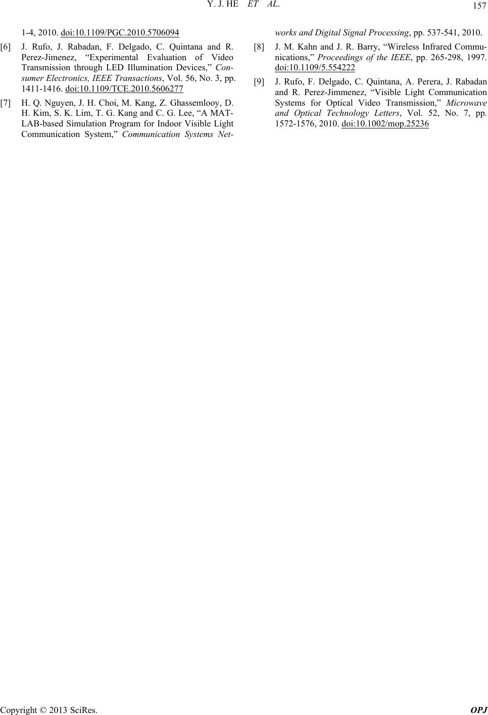 Y. J. HE ET AL. Copyright © 2013 SciRes. OPJ 157 1-4, 2010. doi:10.1109/PGC.2010.5706094 [6] J. Rufo, J. Rabadan, F. Delgado, C. Quintana and R. Perez-Jimenez, “Experimental Evaluation of Video Transmission through LED Illumination Devices,” Con- sumer Electronics, IEEE Transactions, Vol. 56, No. 3, pp. 1411-1416. doi:10.1109/TCE.2010.5606277 [7] H. Q. Nguyen, J. H. Choi, M. Kang, Z. Ghassemlooy, D. H. Kim, S. K. Lim, T. G. Kang and C. G. Lee, “A MAT- LAB-based Simulation Program for Indoor Visible Light Communication System,” Communication Systems Net- works and Digital Signal Processing, pp. 537-541, 2010. [8] J. M. Kahn and J. R. Barry, “Wireless Infrared Commu- nications,” Proceedings of the IEEE, pp. 265-298, 1997. doi:10.1109/5.554222 [9] J. Rufo, F. Delgado, C. Quintana, A. Perera, J. Rabadan and R. Perez-Jimmenez, “Visible Light Communication Systems for Optical Video Transmission,” Microwave and Optical Technology Letters, Vol. 52, No. 7, pp. 1572-1576, 2010. doi:10.1002/mop.25236 |