Paper Menu >>
Journal Menu >>
 Optics and Photonics Journal, 2013, 3, 6-10 doi:10.4236/opj.2013.32B002 Published Online June 2013 (http://www.scirp.org/journal/opj) New Technology of Laser Parallel Thermocracking of Brittle Materials Vladimir Stepanovich Kondratenko, Vladimir Yeugenyevich Borisovsky, Alexander Sergeevich Naumov, Anton Vladimirovich Sorokin Moscow State University of Instrument Engineering and Computer Science, Moscow, Russia Email: vsk1950@mail.ru Received 2013 ABSTRACT This paper is devoted to the development of new technology called laser parallel thermocracking that applicable for brittle nonmetallic materials such as glass, sapphire, silicon etc. The mathematical model of laser parallel thermocrack- ing process is introduced. Results of experimental researches are shown in order that define the interrelation between the basic parameters of laser parallel thermocracking process. Keywords: Component; Laser Parallel Thermocracking; Glass; Sapphire; Ingot; Laser Wafer Slicing; Temperature Stresses 1. Introduction This task is devoted to the solution of the actual problem in the manufacturing of instrument thin plates (wafers) of glass, sapphire, monocrystalline quartz, silicon and gal- lium arsenide in the manufacture of micro- and optoelec- tronics. Existing conventional technology of thin wafers based on the mechanical cutting by diamond abrasives tools. It includes the following operations: wire sawing of ingots, grinding, lapping and polishing. Conventional technolo- gies have the following disadvantages: High consumption of raw material, coupled with a large cutting width comparable with the thickness of the wafers. The low productivity of the diamond abrasive cut- ting process with subsequent grinding and polish- ing of wafers. Greater depth of the damaged layer (Rz) requires the long time grinding and polishing of the wafer surfaces. These defects cannot be eliminated by improving of existing technologies, some of which are reached its lim- its. The elimination of disadvantage is only possible by the development of the fundamentally new material slic- ing process. In the last decade, the method of laser controlled thermocracking (LCT) has got the rapid development and application in various fields of science and technology that is applicable for a wide class of brittle nonmetallic materials such as all types of glasses, sapphire, quarts, different ceramics, silicon, gallium arsenide etc. LCT method was firstly developed in Russia [1]. There is also the method of laser thermocracking, in which the crack propagates in the volume of the material parallel to its surface, the so-called laser parallel thermocracking (LPT), which has the first reference in the literature [2,3]. The task of this work is to develop a new high-tech industrial process, based on the proposed LPT method, which could be applied for the slicing of the thick work- piece onto thin wafers of various brittle nonmetallic ma- terials, used in micro- and optoelectronics. 2. Mathematical Model of the Laser Parallel Thermocracking Process The LPT method means the following. The radiation of the brittle material surface by a laser with a wavelength where the one is nontransparent, some of the energy is reflected and the rest is absorbed and excreted in the form of thermal energy in a thin surface layer. Compres- sion stresses arise in the heat-affected zone of surface layers and one are compensated by tensile stresses at the certain depth in the material volume. Tensile stresses can lead to the cracking in the material parallel its surface under certain conditions. The mathematical model is based on the heat conduc- tion equations by Fourier transforms in the case of mate- rial heating. The heating is performed by a surface source infinitely extended in the direction of the Y axis. This simplification describes the heating of a strongly absorb- ing material by the central part of the extended laser spot Copyright © 2013 SciRes. OPJ 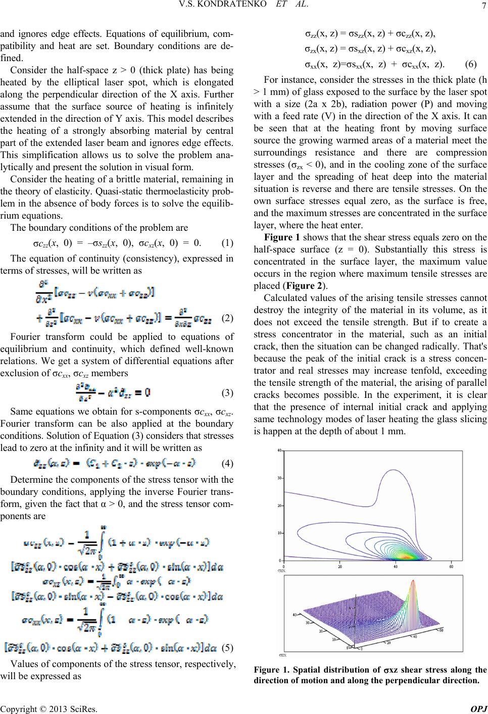 V.S. KONDRATENKO ET AL. 7 and ignores edge effects. Equations of equilibrium, com- patibility and heat are set. Boundary conditions are de- fined. Consider the half-space z > 0 (thick plate) has being heated by the elliptical laser spot, which is elongated along the perpendicular direction of the X axis. Further assume that the surface source of heating is infinitely extended in the direction of Υ axis. This model describes the heating of a strongly absorbing material by central part of the extended laser beam and ignores edge effects. This simplification allows us to solve the problem ana- lytically and present the solution in visual form. Consider the heating of a brittle material, remaining in the theory of elasticity. Quasi-static thermoelasticity prob- lem in the absence of body forces is to solve the equilib- rium equations. The boundary conditions of the problem are σczz(x, 0) = –σszz(x, 0), σcxz(x, 0) = 0. (1) The equation of continuity (consistency), expressed in terms of stresses, will be written as (2) Fourier transform could be applied to equations of equilibrium and continuity, which defined well-known relations. We get a system of differential equations after exclusion of σcxx, σcxz members (3) Same equations we obtain for s-components σcxx, σcxz. Fourier transform can be also applied at the boundary conditions. Solution of Equation (3) considers that stresses lead to zero at the infinity and it will be written as (4) Determine the components of the stress tensor with the boundary conditions, applying the inverse Fourier trans- form, given the fact that α > 0, and the stress tensor com- ponents are (5) Values of components of the stress tensor, respectively, will be expressed as σzz(x, z) = σszz(x, z) + σczz(x, z), σzx(x, z) = σsxz(x, z) + σcxz(x, z), σxx(x, z)=σsxx(x, z) + σcxx(x, z). (6) For instance, consider the stresses in the thick plate (h > 1 mm) of glass exposed to the surface by the laser spot with a size (2a x 2b), radiation power (Ρ) and moving with a feed rate (V) in the direction of the X axis. It can be seen that at the heating front by moving surface source the growing warmed areas of a material meet the surroundings resistance and there are compression stresses (σzx < 0), and in the cooling zone of the surface layer and the spreading of heat deep into the material situation is reverse and there are tensile stresses. On the own surface stresses equal zero, as the surface is free, and the maximum stresses are concentrated in the surface layer, where the heat enter. Figure 1 shows that the shear stress equals zero on the half-space surface (z = 0). Substantially this stress is concentrated in the surface layer, the maximum value occurs in the region where maximum tensile stresses are placed (Figure 2). Calculated values of the arising tensile stresses cannot destroy the integrity of the material in its volume, as it does not exceed the tensile strength. But if to create a stress concentrator in the material, such as an initial crack, then the situation can be changed radically. That's because the peak of the initial crack is a stress concen- trator and real stresses may increase tenfold, exceeding the tensile strength of the material, the arising of parallel cracks becomes possible. In the experiment, it is clear that the presence of internal initial crack and applying same technology modes of laser heating the glass slicing is happen at the depth of about 1 mm. Figure 1. Spatial distribution of xz shear stress along the direction of motion and along the perpendicular direction. Copyright © 2013 SciRes. OPJ 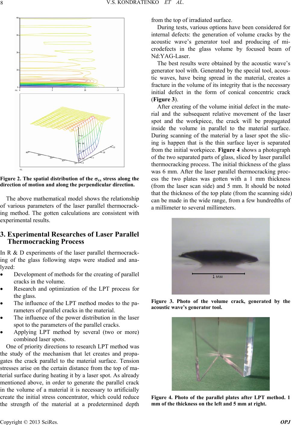 V.S. KONDRATENKO ET AL. 8 Figure 2. The spatial distribution of the xx stress along the direction of motion and along the perpendicular direction. The above mathematical model shows the relationship of various parameters of the laser parallel thermocrack- ing method. The gotten calculations are consistent with experimental results. 3. Experimental Researches of Laser Parallel Thermocracking Process In R & D experiments of the laser parallel thermocrack- ing of the glass following steps were studied and ana- lyzed: Development of methods for the creating of parallel cracks in the volume. Research and optimization of the LPT process for the glass. The influence of the LPT method modes to the pa- rameters of parallel cracks in the material. The influence of the power distribution in the laser spot to the parameters of the parallel cracks. Applying LPT method by several (two or more) combined laser spots. One of priority directions to research LPT method was the study of the mechanism that let creates and propa- gates the crack parallel to the material surface. Tension stresses arise on the certain distance from the top of ma- terial surface during heating it by a laser spot. As already mentioned above, in order to generate the parallel crack in the volume of a material it is necessary to artificially create the initial stress concentrator, which could reduce the strength of the material at a predetermined depth from the top of irradiated surface. During tests, various options have been considered for internal defects: the generation of volume cracks by the acoustic wave’s generator tool and producing of mi- crodefects in the glass volume by focused beam of Nd:YAG-Laser. The best results were obtained by the acoustic wave’s generator tool with. Generated by the special tool, acous- tic waves, have being spread in the material, creates a fracture in the volume of its integrity that is the necessary initial defect in the form of conical concentric crack (Figure 3). After creating of the volume initial defect in the mate- rial and the subsequent relative movement of the laser spot and the workpiece, the crack will be propagated inside the volume in parallel to the material surface. During scanning of the material by a laser spot the slic- ing is happen that is the thin surface layer is separated from the initial workpiece. Figure 4 shows a photograph of the two separated parts of glass, sliced by laser parallel thermocracking process. The initial thickness of the glass was 6 mm. After the laser parallel thermocracking proc- ess the two plates was gotten with a 1 mm thickness (from the laser scan side) and 5 mm. It should be noted that the thickness of the top plate (from the scanning side) can be made in the wide range, from a few hundredths of a millimeter to several millimeters. Figure 3. Photo of the volume crack, generated by the acoustic wave’s generator tool. Figure 4. Photo of the parallel plates after LPT method. 1 mm of the thickness on the left and 5 mm at right. Copyright © 2013 SciRes. OPJ 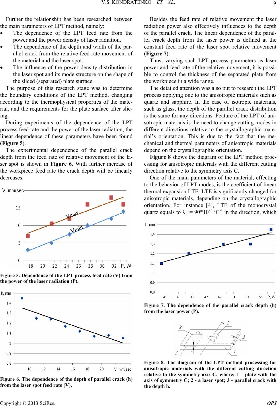 V.S. KONDRATENKO ET AL. 9 Further the relationship has been researched between the main parameters of LPT method, namely: The dependence of the LPT feed rate from the power and the power density of laser radiation. The dependence of the depth and width of the par- allel crack from the relative feed rate movement of the material and the laser spot. The influence of the power density distribution in the laser spot and its mode structure on the shape of the sliced (separated) plate surface. The purpose of this research stage was to determine the boundary conditions of the LPT method, changing according to the thermophysical properties of the mate- rial, and the requirements for the plate surface after slic- ing. During experiments of the dependence of the LPT process feed rate and the power of the laser radiation, the linear dependence of these parameters have been found (Figure 5). The experimental dependence of the parallel crack depth from the feed rate of relative movement of the la- ser spot is shown in Figure 6. With further increase of the workpiece feed rate the crack depth will be linearly decreases. Figure 5. Dependence of the LPT process feed rate (V) from the power of the laser radiation (P). Figure 6. The dependence of the depth of parallel crack (h) from the laser spot feed rate (V). Besides the feed rate of relative movement the laser radiation power also effectively influences to the depth of the parallel crack. The linear dependence of the paral- lel crack depth from the laser power is defined at the constant feed rate of the laser spot relative movement (Figure 7). Thus, varying such LPT process parameters as laser power and feed rate of the relative movement, it is possi- ble to control the thickness of the separated plate from the workpiece in a wide range. The detailed attention was also put to research the LPT process applying one to the anisotropic materials such as quartz and sapphire. In the case of isotropic materials, such as glass, the depth of the parallel crack distribution is the same for any directions. Feature of the LPT of ani- sotropic materials is the need to change cutting modes in different directions relative to the crystallographic mate- rial’s orientation. This is due to the fact that the me- chanical and thermal parameters of anisotropic materials depend on the crystallographic orientation. Figure 8 shows the diagram of the LPT method proc- essing for anisotropic materials with the different cutting direction relative to the symmetry axis C. One of the main parameters of the material, effecting to the behavior of LPT modes, is the coefficient of linear thermal expansion LTE. LTE is significantly changed for anisotropic materials, depending on the crystallographic orientation. For instance [4], LTE of the monocrystal quartz equals to λ║ = 90*10-7 °C-1 in the direction, which Figure 7. The dependence of the parallel crack depth (h) from the laser power (P). Figure 8. The diagram of the LPT method processing for anisotropic materials with the different cutting direction relative to the symmetry axis C, where: 1 - plate with the axis of symmetry C; 2 - a laser spot; 3 - parallel crack with the depth h. Copyright © 2013 SciRes. OPJ 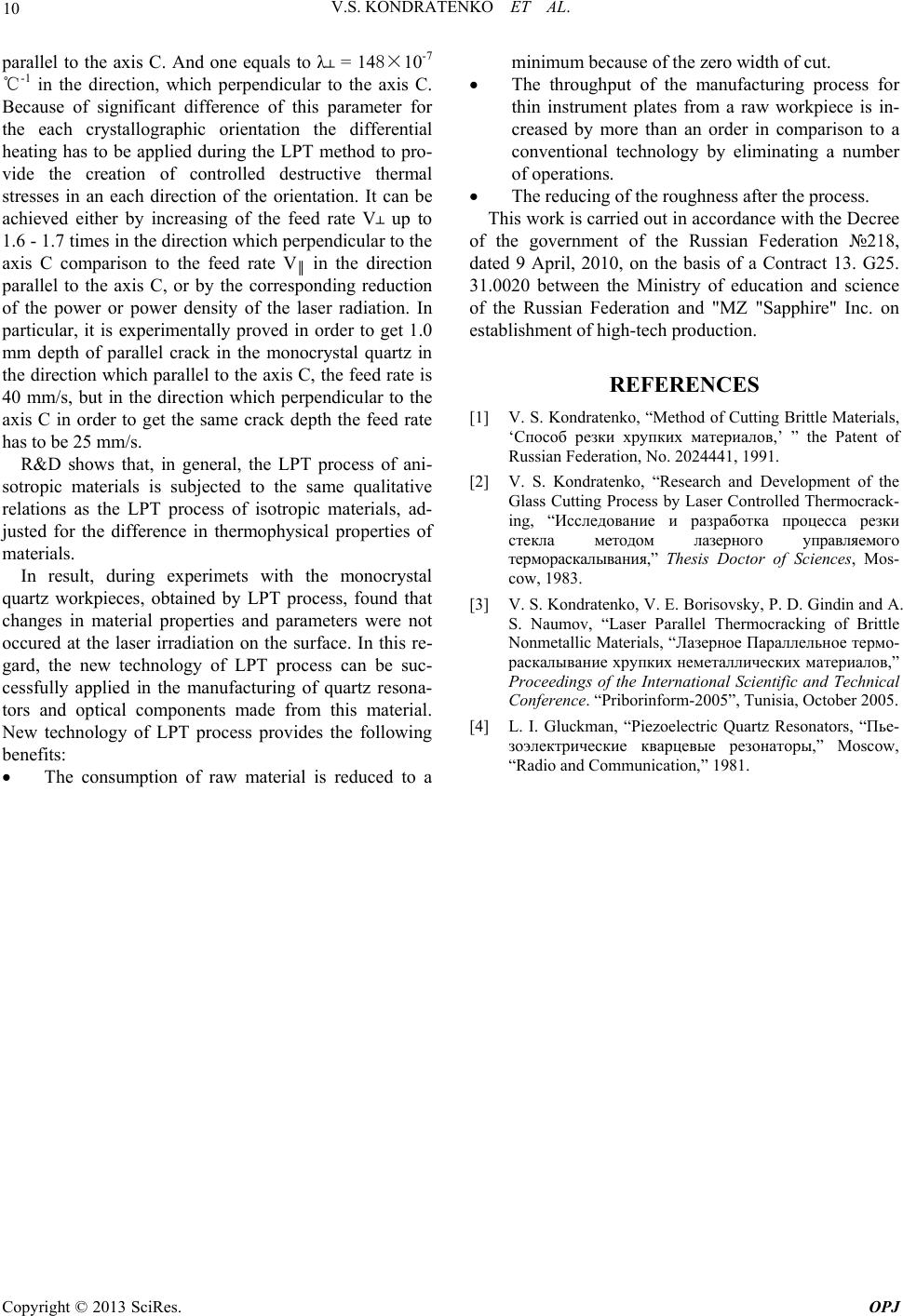 V.S. KONDRATENKO ET AL. Copyright © 2013 SciRes. OPJ 10 parallel to the axis C. And one equals to λ┴ = 148×10-7 ℃-1 in the direction, which perpendicular to the axis C. Because of significant difference of this parameter for the each crystallographic orientation the differential heating has to be applied during the LPT method to pro- vide the creation of controlled destructive thermal stresses in an each direction of the orientation. It can be achieved either by increasing of the feed rate V┴ up to 1.6 - 1.7 times in the direction which perpendicular to the axis C comparison to the feed rate V║ in the direction parallel to the axis C, or by the corresponding reduction of the power or power density of the laser radiation. In particular, it is experimentally proved in order to get 1.0 mm depth of parallel crack in the monocrystal quartz in the direction which parallel to the axis C, the feed rate is 40 mm/s, but in the direction which perpendicular to the axis C in order to get the same crack depth the feed rate has to be 25 mm/s. R&D shows that, in general, the LPT process of ani- sotropic materials is subjected to the same qualitative relations as the LPT process of isotropic materials, ad- justed for the difference in thermophysical properties of materials. In result, during experimets with the monocrystal quartz workpieces, obtained by LPT process, found that changes in material properties and parameters were not occured at the laser irradiation on the surface. In this re- gard, the new technology of LPT process can be suc- cessfully applied in the manufacturing of quartz resona- tors and optical components made from this material. New technology of LPT process provides the following benefits: The consumption of raw material is reduced to a minimum because of the zero width of cut. The throughput of the manufacturing process for thin instrument plates from a raw workpiece is in- creased by more than an order in comparison to a conventional technology by eliminating a number of operations. The reducing of the roughness after the process. This work is carried out in accordance with the Decree of the government of the Russian Federation №218, dated 9 April, 2010, on the basis of a Contract 13. G25. 31.0020 between the Ministry of education and science of the Russian Federation and "MZ "Sapphire" Inc. on establishment of high-tech production. REFERENCES [1] V. S. Kondratenko, “Method of Cutting Brittle Materials, ‘Способ резки хрупких материалов,’ ” the Patent of Russian Federation, No. 2024441, 1991. [2] V. S. Kondratenko, “Research and Development of the Glass Cutting Process by Laser Controlled Thermocrack- ing, “Исследование и разработка процесса резки стекла методом лазерного управляемого термораскалывания,” Thesis Doctor of Sciences, Mos- cow, 1983. [3] V. S. Kondratenko, V. E. Borisovsky, P. D. Gindin and A. S. Naumov, “Laser Parallel Thermocracking of Brittle Nonmetallic Materials, “Лазерное Параллельное термо- раскалывание хрупких неметаллических материалов,” Proceedings of the International Scientific and Technical Conference. “Priborinform-2005”, Tunisia, October 2005. [4] L. I. Gluckman, “Piezoelectric Quartz Resonators, “Пье- зоэлектрические кварцевые резонаторы,” Moscow, “Radio and Communication,” 1981. |