 International Journal of Geosciences, 2013, 4, 863-870 http://dx.doi.org/10.4236/ijg.2013.45080 Published Online July 2013 (http://www.scirp.org/journal/ijg) Swelling Measurements of a Low Rank Coal in Supercritical CO2 Ferian Anggara1,2, Kyuro Sasaki1, Yuichi Sugai1 1Department of Earth Resources Engineering, Kyushu University, Fukuoka, Japan 2Department of Geological Engineering, Gadjah Mada University, Yogyakarta, Indonesia Email: ferian@ugm.ac.id, krsasaki@mine.kyushu-u.ac.id, sugai@mine.kyushu-u.ac.id Received March 28, 2013; revised April 30, 2013; accepted May 27, 2013 Copyright © 2013 Ferian Anggara et al. This is an open access article distributed under the Creative Commons Attribution License, which permits unrestricted use, distribution, and reproduction in any medium, provided the original work is properly cited. ABSTRACT Coal swelling in the presence of water as well as CO2 is a well-known phenomenon, and these may affect the perme- ability of coal. Quantifying swelling effects is becoming an important issue to verify the suitability of particular coal seams for CO2-enhanced coal bed methane recovery projects. In this report, coal swelling experiments using a visuali- zation method in the CO2 supercritical conditions were conducted on crushed coal samples. The measurement apparatus was designed specifically for the present swelling experiment using a visualization method. Crushed coal samples were used instead of block coal samples to shorten equilibrium time and to solve the problem of limited availability of core coal samples. Dry and wet coal samples were used in the experiments because there is relatively limited information about how the swelling of coal by CO2 is affected by water saturation. Moreover, some coal seams are saturated with water in initial reservoir conditions. The maximum volumetric swelling was around 3% at 10 MPa for dry samples and almost half that at the same pressure for wet samples. The wet samples showed lower volumetric swelling than dry ones because the wet coal samples were already swollen by water. Experimental results obtained for swelling were compara- ble with other reports. Our visualization method using crushed samples has advantages in terms of sample preparation and experimental execution compared with the other methods used to measure coal swelling using block samples. Keywords: Coal Swelling Experiments; Visualization Method; CO2-Enhanced Coal Bed Methane Recovery; Low Rank Coal 1. Introduction CO2 capture and storage (CCS) is a method expected to reduce emission of CO2 into the atmosphere. In fact, geological sequestration is most likely to be the only op- tion that will allow CO2 storage in large enough quanti- ties over long geological periods of time. One of the geological sequestration options is injection of CO2 into coal seams. This option is considered to be a safe and effective method for permanently storing CO2 with the added value of enhanced coal bed methane recovery (CO2-ECBMR). It has been suggested that the CO2 sorp- tion capacity of coal seams is typically between 2 to 10 times higher than that for CH4 depending on coal rank [1-3]. CO2 injection into a coal seam increases the rate of CH4 production considerably [4]. However, CO2 is also known as a swelling agent for coal. Coal swelling in the presence of water or CO2 is a well-known phenomenon, and may affect the permeability of coal. Because the permeability of a coal is perhaps the most important fac- tor controlling the economic viability of CO2-ECBMR, thus quantifying the effect of swelling on permeability has become an important issue. A number of studies investigating CO2-induced swell- ing have been published. The maximum volumetric swelling has been reported as 1% - 5% depending on coal rank [5-7]. Reduction of CO2 injectivity has been observed in some CO2-ECBMR field trials. One of these projects was carried at Yubari, Hokkaido, Japan. The Yubari pilot project for CO2-ECBMR identified the problem of low injectivity of CO2 caused by a reduction in permeability induced by coal swelling [3]. The decay ratios of daily CO2 injection rate measured in the Yubari pilot test are shown in Figure 1. A field experiment of CO2-ECBMR carried out in the upper Silesian basin of Poland is another example of a pilot project that observed decreasing injectivity caused by swelling. Evaluation of wellhead pressure and tem- perature data during the pressure buildup and fall-off of C opyright © 2013 SciRes. IJG 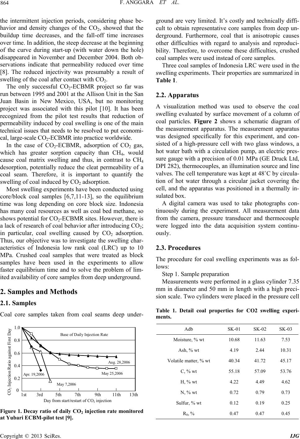 F. ANGGARA ET AL. 864 the intermittent injection periods, considering phase be- havior and density changes of the CO2, showed that the buildup time decreases, and the fall-off time increases over time. In addition, the steep decrease at the beginning of the curve during start-up (with water down the hole) disappeared in November and December 2004. Both ob- servations indicate that permeability reduced over time [8]. The reduced injectivity was presumably a result of swelling of the coal after contact with CO2. The only successful CO2-ECBMR project so far was run between 1995 and 2001 at the Allison Unit in the San Juan Basin in New Mexico, USA, but no monitoring project was associated with this pilot [10]. It has been recognized from the pilot test results that reduction of permeability induced by coal swelling is one of the main technical issues that needs to be resolved to put economi- cal, large-scale CO2-ECBMR into practice worldwide. In the case of CO2-ECBMR, adsorption of CO2 gas, which has greater sorption capacity than CH4, would cause coal matrix swelling and thus, in contrast to CH4 desorption, potentially reduce the cleat permeability of a coal seam. Therefore, it is important to quantify the swelling of coal induced by CO2 adsorption. Most swelling experiments have been conducted using core/block coal samples [6,7,11-13], so the equilibrium time was long depending on core block size. Indonesia has many coal resources as well as coal bed methane, so shows potential for CO2-ECBMR sites. However, there is a lack of research of coal behavior after introducing CO2; in particular, coal swelling caused by CO2 adsorption. Thus, our objective was to investigate the swelling char- acteristics of Indonesia low rank coal (LRC) up to 10 MPa. Crushed coal samples that were treated as block samples have been used in the experiments to allow faster equilibrium time and to solve the problem of lim- ited availability of core samples from deep underground. 2. Samples and Methods 2.1. Samples Coal core samples taken from coal seams deep under- 0 0.2 0.4 0.6 0.8 1.0 1s 3r 5th 7th 9th Apr. 19,2006 May 7,2006 Ma CO 2 Injection Ratio against First Day Day from start/restart of CO 2 injec Base of Daily Injection Ra 11th13th y 25,2006 tion Aug. 28,2006 te Figure 1. Decay ratio of daily CO2 injection rate monitored at Yubari ECBM-pilot test [9]. ground are very limited. It’s costly and technically diffi- cult to obtain representative core samples from deep un- derground. Furthermore, coal that is anisotropic causes other difficulties with regard to analysis and reproduci- bility. Therefore, to overcome these difficulties, crushed coal samples were used instead of core samples. Three coal samples of Indonesia LRC were used in the swelling experiments. Their properties are summarized in Table 1. 2.2. Apparatus A visualization method was used to observe the coal swelling evaluated by surface movement of a column of coal particles. Figure 2 shows a schematic diagram of the measurement apparatus. The measurement apparatus was designed specifically for this experiment, and con- sisted of a high-pressure cell with two glass windows, a hot water bath with a circulation pump, an electric pres- sure gauge with a precision of 0.01 MPa (GE Druck Ltd, DPI 282), thermocouples, an illumination source and line valves. The cell temperature was kept at 48˚C by circula- tion of hot water through a circular jacket covering the cell, and the apparatus was positioned in a thermally in- sulated box. A digital camera was used to take photographs con- tinuously during the experiment. All measurement data from the camera, pressure transducer and thermocouple were logged into the data acquisition system continu- ously. 2.3. Procedures The procedure for coal swelling experiments was as fol- lows: Step 1. Sample preparation Measurements were performed in a glass cylinder 7.35 mm in diameter and 50 mm in length with a high preci- sion scale. Two cylinders were placed in the pressure cell Table 1. Detail coal properties for CO2 swelling experi- ments. Adb SK-01 SK-02 SK-03 Moisture, % wt 10.68 11.63 7.53 Ash, % wt 4.19 2.44 10.31 Volatile matter, % wt 40.34 41.72 45.17 C, % wt 55.18 57.09 53.76 H, % wt 4.22 4.49 4.62 N, % wt 0.72 0.79 0.73 Sulfur, % wt 0.12 0.19 0.25 R0, % 0.47 0.47 0.45 Copyright © 2013 SciRes. IJG 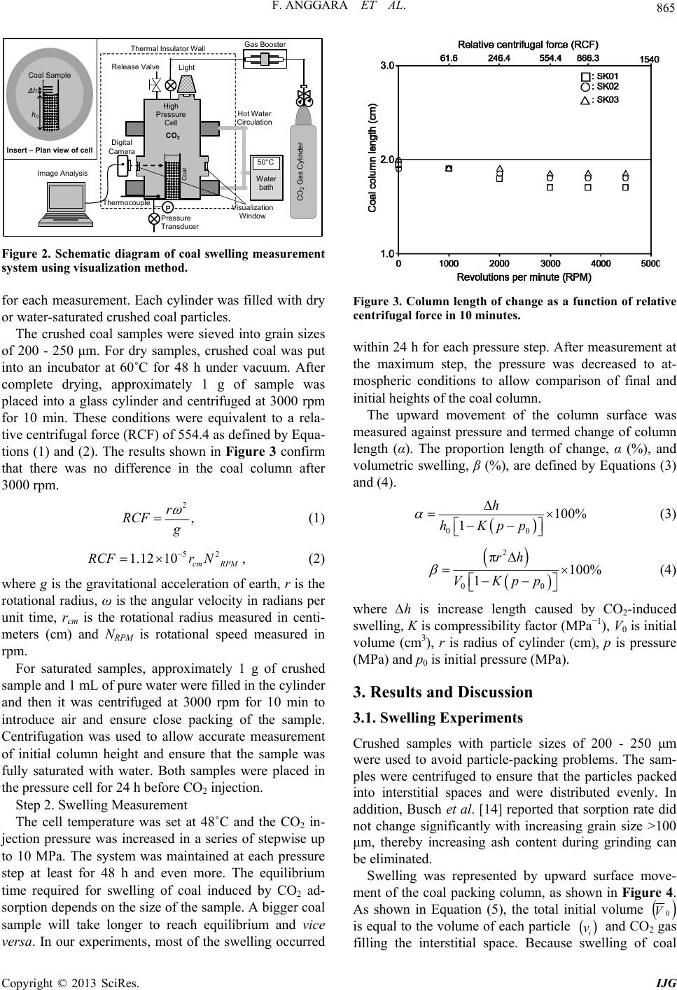 F. ANGGARA ET AL. 865 CO2 Gas Cylinder 50°C Water bath Digital Camera P CO2 Visu Wi alization ndow Li ht Pressure Transducer Thermal Insulato r Wall High Pressure Cell Image Analysis Insert Plan view of cell Coal Gas Booste Hot Circ Releas e Val v e Thermocouple Water ulation Coal Sample h0 ∆h Figure 2. Schematic diagram of coal swelling measurement system using visualization method. for each measurement. Each cylinder was filled with dry or water-saturated crushed coal particles. The crushed coal samples were sieved into grain sizes of 200 - 250 μm. For dry samples, crushed coal was put into an incubator at 60˚C for 48 h under vacuum. After complete drying, approximately 1 g of sample was placed into a glass cylinder and centrifuged at 3000 rpm for 10 min. These conditions were equivalent to a rela- tive centrifugal force (RCF) of 554.4 as defined by Equa- tions (1) and (2). The results shown in Figure 3 confirm that there was no difference in the coal column after 3000 rpm. 2 , r RCF 52 10 cm RPM r N (1) 1.12RCF , (2) where g is the gravitational acceleration of earth, r is the rotational radius, ω is the angular velocity in radians per unit time, rcm is the rotational radius measured in centi- meters (cm) and NRPM is rotational speed measured in rpm. For saturated samples, approximately 1 g of crushed sample and 1 mL of pure water were filled in the cylinder and then it was centrifuged at 3000 rpm for 10 min to introduce air and ensure close packing of the sample. Centrifugation was used to allow accurate measurement of initial column height and ensure that the sample was fully saturated with water. Both samples were placed in the pressure cell for 24 h before CO2 injection. Step 2. Swelling Measurement The cell temperature was set at 48˚C and the CO2 in- jection pressure was increased in a series of stepwise up to 10 MPa. The system was maintained at each pressure step at least for 48 h and even more. The equilibrium time required for swelling of coal induced by CO2 ad- sorption depends on the size of the sample. A bigger coal sample will take longer to reach equilibrium and vice versa. In our experiments, most of the swelling occurred Figure 3. Column length of change as a function of relative centrifugal force in 10 minutes. within 24 h for each pressure step. After measurement at the maximum step, the pressure was decreased to at- mospheric conditions to allow comparison of final and initial heights of the coal column. The upward movement of the column surface was measured against pressure and termed change of column length (α). The proportion length of change, α (%), and volumetric swelling, β (%), are defined by Equations (3) and (4). 00 100% 1 h hKpp (3) 2 00 π100% 1 rh VKpp (4) where ∆h is increase length caused by CO2-induced swelling, K is compressibility factor (MPa−1), V0 is initial volume (cm3), r is radius of cylinder (cm), p is pressure (MPa) and p0 is initial pressure (MPa). 3. Results and Discussion 3.1. Swelling Experiments Crushed samples with particle sizes of 200 - 250 μm were used to avoid particle-packing problems. The sam- ples were centrifuged to ensure that the particles packed into interstitial spaces and were distributed evenly. In addition, Busch et al. [14] reported that sorption rate did not change significantly with increasing grain size >100 μm, thereby increasing ash content during grinding can be eliminated. Swelling was represented by upward surface move- ment of the coal packing column, as shown in Figure 4. As shown in Equation (5), the total initial volume 0 is equal to the volume of each particle i and CO2 gas filling the interstitial space. Because swelling of coal V v Copyright © 2013 SciRes. IJG 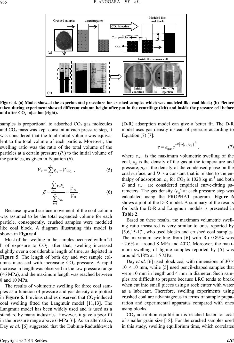 F. ANGGARA ET AL. Copyright © 2013 SciRes. IJG 866 Crushed sam les Centrifugalize CO 2 Injection Inside the pressure cel Initial condition Afte r CO 2 injection Coal particles CO 2 Modele d li coal block ke a b (a) (b) Figure 4. (a) Model showed the experimental procedure for crushed samples which was modeled like coal block; (b) Picture taken during experiment showed different column height after put in the centrifuge (left) and inside the pressure cell before and after CO2 injection (right). samples is proportional to adsorbed CO2 gas molecules and CO2 mass was kept constant at each pressure step, it was considered that the total initial volume was equiva- lent to the total volume of each particle. Moreover, the swelling ratio was the ratio of the total volume of the particles at a certain pressure (Pn) to the initial volume of the particles, as given in Equation (6). 2 0 1 n CO i i VvV 0, (5) 1 0 0 1 n n in i n i i vP V V v . (6) Because upward surface movement of the coal column was assumed to be the total expanded volume for each particle, consequently, crushed samples were modeled like coal block. A diagram illustrating this model is shown in Figure 4. Most of the swelling in the samples occurred within 24 h of exposure to CO2; after that, swelling increased slightly over a considerable length of time, as depicted in Figure 5. The length of both dry and wet sample col- umns increased with increasing CO2 pressure. A rapid increase in length was observed in the low pressure range (≤6 MPa), and the maximum length was reached between 8 and 10 MPa. The results of volumetric swelling for three coal sam- ples as a function of pressure and gas density are plotted in Figure 6. Previous studies observed that CO2-induced coal swelling fitted the Langmuir model [11,13]. The Langmuir model has been widely used and is used as a standard by many industries. However, it gave a poor fit in the pressure range above 6 MPa [6]. As an alternative, Day et al. [6] suggested that the Dubinin-Radushkevich (D-R) adsorption model can give a better fit. The D-R model uses gas density instead of pressure according to Equation (7) [7]: 2 ln max eag D , (7) where εmax is the maximum volumetric swelling of the coal, ρg is the density of the gas at the temperature and pressure, ρa is the density of the condensed phase on the coal surface, and D is a constant that is related to the en- thalpy of adsorption. ρa for CO2 is 1028 kg m-3 and both D and εmax are considered empirical curve-fitting pa- rameters. The gas density (ρg) at each pressure step was calculated using the PROPHAT program. Figure 6 shows a plot of the D-R model. A summary of the results for both the D-R and Langmuir models is presented in Table 2. Based on these results, the maximum volumetric swell- ing ratio measured is very similar to ones reported by [5,6,15-17], who used blocks and crushed coal samples. The maximum swelling from [6] with Ro 0.89% was ~2.6% at around 8 MPa and 40˚C. Moreover, the maxi- mum swelling of lignite samples reported by [5] was around 4.18% at 1.5 MPa. Day et al. [6] used block coal with dimensions of 30 × 10 × 10 mm, while [5] used pencil-shaped samples that were 10 mm in length and 4 mm in diameter. Such sam- ples are difficult to prepare because LRC tends to break when cut into small pieces using a rock cutter with water as a lubricant. Therefore, swelling experiments using crushed coal are advantageous in terms of sample prepa- ration and experimental apparatus compared with ones using blocks. CO2 adsorption equilibrium is reached faster for coal of smaller grain size [18]. For the crushed samples used in this study, swelling equilibrium time, which correlates 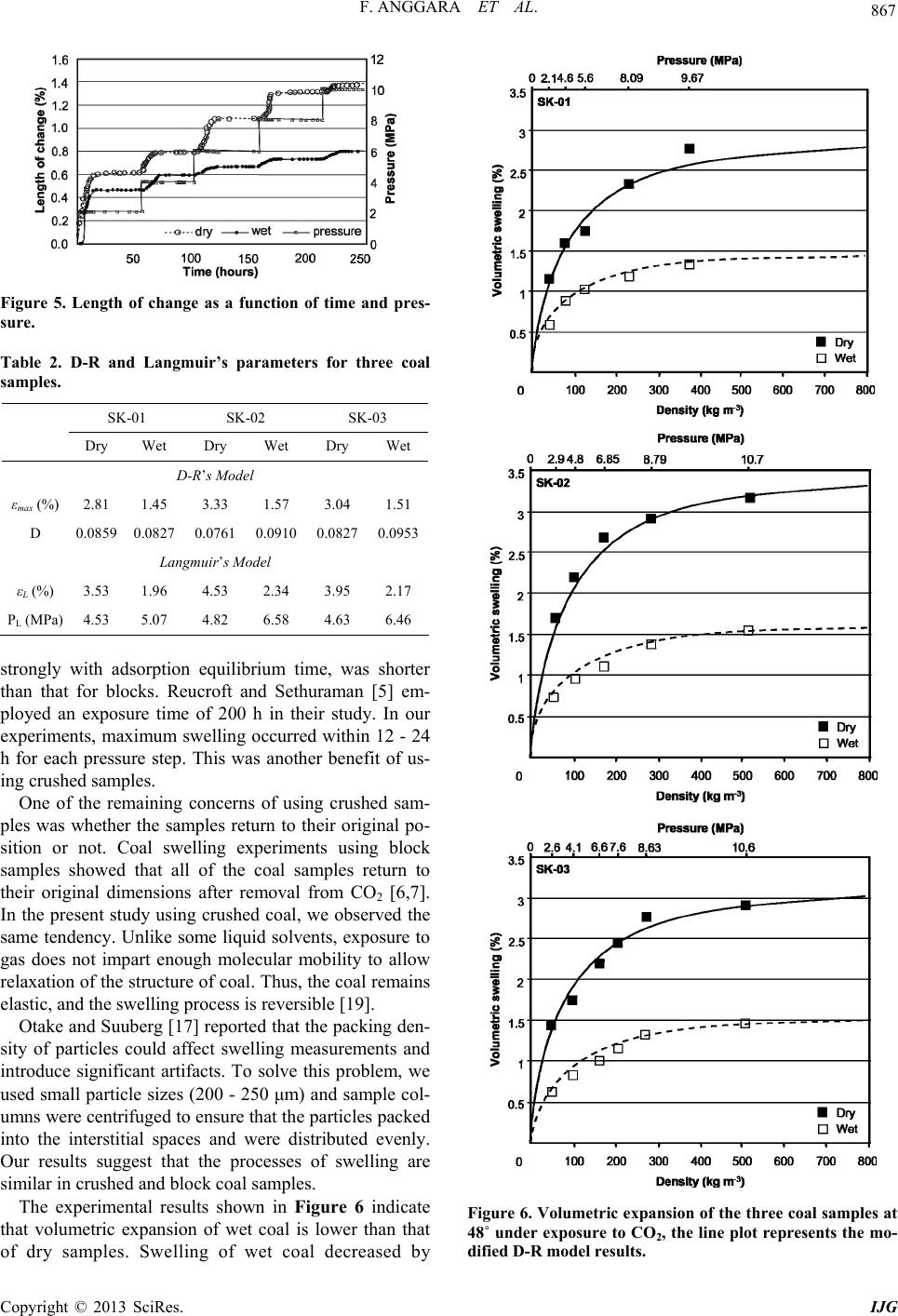 F. ANGGARA ET AL. 867 Figure 5. Length of change as a function of time and pres- sure. Table 2. D-R and Langmuir’s parameters for three coal samples. SK-01 SK-02 SK-03 Dry Wet Dry Wet Dry Wet D-R’s Model εmax (%) 2.81 1.45 3.33 1.57 3.04 1.51 D 0.0859 0.0827 0.0761 0.0910 0.0827 0.0953 Langmuir’s Model εL (%) 3.53 1.96 4.53 2.34 3.95 2.17 PL (MPa) 4.53 5.07 4.82 6.58 4.63 6.46 strongly with adsorption equilibrium time, was shorter than that for blocks. Reucroft and Sethuraman [5] em- ployed an exposure time of 200 h in their study. In our experiments, maximum swelling occurred within 12 - 24 h for each pressure step. This was another benefit of us- ing crushed samples. One of the remaining concerns of using crushed sam- ples was whether the samples return to their original po- sition or not. Coal swelling experiments using block samples showed that all of the coal samples return to their original dimensions after removal from CO2 [6,7]. In the present study using crushed coal, we observed the same tendency. Unlike some liquid solvents, exposure to gas does not impart enough molecular mobility to allow relaxation of the structure of coal. Thus, the coal remains elastic, and the swelling process is reversible [19]. Otake and Suuberg [17] reported that the packing den- sity of particles could affect swelling measurements and introduce significant artifacts. To solve this problem, we used small particle sizes (200 - 250 μm) and sample col- umns were centrifuged to ensure that the particles packed into the interstitial spaces and were distributed evenly. Our results suggest that the processes of swelling are similar in crushed and block coal samples. The experimental results shown in Figure 6 indicate that volumetric expansion of wet coal is lower than that of dry samples. Swelling of wet coal decreased by Figure 6. Volumetric expansion of the three coal samples at 48˚ under exposure to CO2, the line plot represents the mo- dified D-R model results. Copyright © 2013 SciRes. IJG 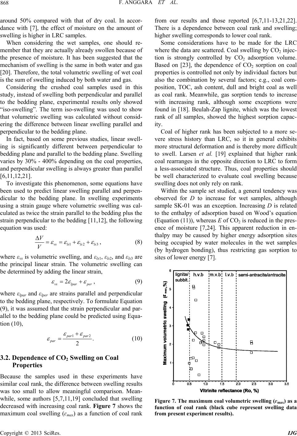 F. ANGGARA ET AL. 868 around 50% compared with that of dry coal. In accor- dance with [7], the effect of moisture on the amount of swelling is higher in LRC samples. When considering the wet samples, one should re- member that they are actually already swollen because of the presence of moisture. It has been suggested that the mechanism of swelling is the same in both water and gas [20]. Therefore, the total volumetric swelling of wet coal is the sum of swelling induced by both water and gas. Considering the crushed coal samples used in this study, instead of swelling both perpendicular and parallel to the bedding plane, experimental results only showed “iso-swelling”. The term iso-swelling was used to show that volumetric swelling was calculated without consid- ering the difference between linear swelling parallel and perpendicular to the bedding plane. In fact, based on some previous studies, linear swell- ing is significantly different between perpendicular to bedding plane and parallel to the bedding plane. Swelling varies by 30% - 400% depending on the coal properties, and perpendicular swelling is always greater than parallel [6,11,12,21]. To investigate this phenomenon, some equations have been used to predict linear swelling parallel and perpen- dicular to the bedding plane. In swelling experiments using a strain gauge where volumetric swelling was cal- culated as twice the strain parallel to the bedding plus the strain perpendicular to the bedding [11,12], the following equation was used: 123ls lslsvs V V 2lpar per , (8) where εvs is volumetric swelling, and εls1, εls2, and εls3 are the principal linear strain. The volumetric swelling can be determined by adding the linear strain, vs , (9) where εlpar and εlper are strains parallel and perpendicular to the bedding plane, respectively. To formulate Equation (9), it was assumed that the strain perpendicular and par- allel to the bedding plane could be predicted using Equa- tion (10), 12 . 2 par par par (10) 3.2. Dependence of CO2 Swelling on Coal Properties Because the samples used in these experiments have similar coal rank, the difference between swelling results was too small to allow meaningful comparison. Mean- while, some authors [5,7,11,19] concluded that swelling decreased with increasing coal rank. Figure 7 shows the maximum coal swelling (ɛmax) as a function of coal rank from our results and those reported [6,7,11-13,21,22]. There is a dependence between coal rank and swelling; higher swelling corresponds to lower coal rank. Some considerations have to be made for the LRC where the data are scattered. Coal swelling by CO2 injec- tion is strongly controlled by CO2 adsorption volume. Based on [23], the dependence of CO2 sorption on coal properties is controlled not only by individual factors but also the combination by several factors; e.g., coal com- position, TOC, ash content, dull and bright coal as well as coal rank. Meanwhile, gas sorption tends to increase with increasing rank, although some exceptions were found in [18]. Beulah-Zap lignite, which was the lowest rank of all samples, showed the highest sorption capac- ity. Coal of higher rank has been subjected to a more se- vere stress history than LRC, so it in general exhibits more structural deformation and is thereby more difficult to swell. Larsen et al. [19] explained that higher rank coal rearranges in the opposite direction to LRC to form a less-associated structure. Thus, coal properties should be well characterized to evaluate coal swelling because swelling does not only rely on rank. Within the sample set studied, a general tendency was observed for D to increase for wet samples, although sample SK-01 was an exception. Increasing D is related to the enthalpy of adsorption based on Wood’s equation (Equation (11)), whereas E of CO2 is reduced in the pres- ence of moisture [7,24]. This apparent reduction in en- thalpy may be caused by higher energy adsorption sites being occupied by water molecules in the wet samples (by hydrogen bonding), thus restricting gas sorption to sites of lower energy [7]. Figure 7. The maximum coal volumetric swelling (ɛmax) as a function of coal rank (black cube represent swelling data from present experiment results). Copyright © 2013 SciRes. IJG 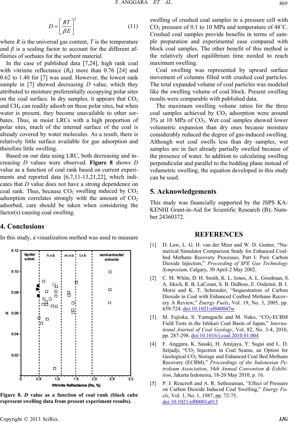 F. ANGGARA ET AL. 869 2 RT DE (11) where R is the universal gas content, T is the temperature and β is a scaling factor to account for the different af- finities of sorbates for the sorbent material. In the case of published data [7,24], high rank coal with vitrinite reflectance (R0) more than 0.76 [24] and 0.62 to 1.40 for [7] was used. However, the lowest rank sample in [7] showed decreasing D value, which they attributed to moisture preferentially occupying polar sites on the coal surface. In dry samples, it appears that CO2 and CH4 can readily adsorb on these polar sites, but when water is present, they become unavailable to other sor- bates. Thus, in moist LRCs with a high proportion of polar sites, much of the internal surface of the coal is already covered by water molecules. As a result, there is relatively little surface available for gas adsorption and therefore little swelling. Based on our data using LRC, both decreasing and in- creasing D values were observed. Figure 8 shows D value as a function of coal rank based on current experi- ments and reported data [6,7,11-13,21,22], which indi- cates that D value does not have a strong dependence on coal rank. Thus, because CO2 swelling induced by CO2 adsorption correlates strongly with the amount of CO2 adsorbed, care should be taken when considering the factor(s) causing coal swelling. 4. Conclusions In this study, a visualization method was used to measure Figure 8. D value as a function of coal rank (black cube represent swelling data from present experiment results). swelling of crushed coal samples in a pressure cell with CO2 pressure of 0.1 to 10 MPa and temperature of 48˚C. Crushed coal samples provide benefits in terms of sam- ple preparation and experimental ease compared with block coal samples. The other benefit of this method is the relatively short equilibrium time needed to reach maximum swelling. Coal swelling was represented by upward surface movement of columns filled with crushed coal particles. The total expanded volume of coal particles was modeled like the swelling volume of coal block. Present swelling results were comparable with published data. The maximum swelling volume ratios for the three coal samples achieved by CO2 adsorption were around 3% at 10 MPa of CO2. Wet coal samples showed lower volumetric expansion than dry ones because moisture considerably reduced the degree of gas-induced swelling. Although wet coal swells less than dry samples, wet samples are in fact already partially swelled because of the presence of water. In addition to calculating swelling perpendicular and parallel to the bedding plane instead of volumetric swelling, the equation developed in this study can be used. 5. Acknowledgements This study was financially supported by the JSPS KA- KENHI Grant-in-Aid for Scientific Research (B); Num- ber 24360372. REFERENCES [1] D. Law, L. G. H. van der Meer and W. D. Gunter, “Nu- merical Simulator Comparison Study for Enhanced Coal- bed Methane Recovery Processes, Part I: Pure Carbon Dioxide Injection,”Proceeding of SPE Gas Technology Symposium, Calgary, 30 April-2 May 2002. [2] C. M. White, D. H. Smith, K. L. Jones, A. L. Goodman, S. A. Jikich, R. B. LaCount, S. B. DuBose, E. Ozdemir, B. I. Morsi and K. T. Schroeder, “Sequestration of Carbon Dioxide in Coal with Enhanced Coalbed Methane Recov- ery A Review,” Energy Fuels, Vol. 19, No. 3, 2005, pp. 659-724. doi:10.1021/ef040047w [3] M. Fujioka, S. Yamaguchi and M. Nako, “CO2-ECBM Field Tests in the Ishikari Coal Basin of Japan,” Interna- tional Journal of Coal Geology, Vol. 82, No. 3-4, 2010, pp. 287-298. doi:10.1016/j.coal.2010.01.004 [4] F. Anggara, K. Sasaki, H. Amijaya, Y. Sugai and L. D. Setjadji, “CO2 Injection in Coal Seams, an Option for Geological CO2 Storage and Enhanced Coal Bed Methane Recovery (ECBM),” Proceedings of the Indonesian Pe- troleum Association, 34th Annual Convention & Exhibi- tion, Jakarta Indonesia, 18-20 May 2010, p. 16. [5] P. J. Reucroft and A. R. Sethuraman, “Effect of Pressure on Carbon Dioxide Induced Coal Swelling,” Energy Fu- els, Vol. 1, No. 1, 1987, pp. 72-75. doi:10.1021/ef00001a013 Copyright © 2013 SciRes. IJG 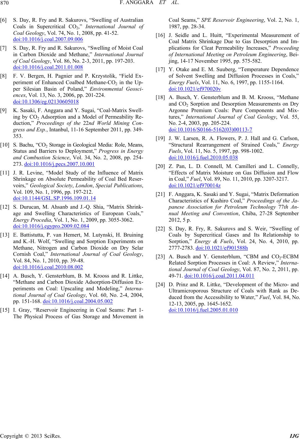 F. ANGGARA ET AL. Copyright © 2013 SciRes. IJG 870 [6] S. Day, R. Fry and R. Sakurovs, “Swelling of Australian Coals in Supercritical CO2,” International Journal of Coal Geology, Vol. 74, No. 1, 2008, pp. 41-52. doi:10.1016/j.coal.2007.09.006 [7] S. Day, R. Fry and R. Sakurovs, “Swelling of Moist Coal in Carbon Dioxide and Methane,” International Journal of Coal Geology, Vol. 86, No. 2-3, 2011, pp. 197-203. doi:10.1016/j.coal.2011.01.008 [8] F. V. Bergen, H. Pagnier and P. Krzystolik, “Field Ex- periment of Enhanced Coalbed Methane-CO2 in the Up- per Silesian Basin of Poland,” Environmental Geosci- ences, Vol. 13, No. 3, 2006, pp. 201-224. doi:10.1306/eg.02130605018 [9] K. Sasaki, F. Anggara and Y. Sugai, “Coal-Matrix Swell- ing by CO2 Adsorption and a Model of Permeability Re- duction,” Proceedings of the 22nd World Mining Con- gress and Exp., Intanbul, 11-16 September 2011, pp. 349- 353. [10] S. Bachu, “CO2 Storage in Geological Media: Role, Means, Status and Barriers to Deployment,” Progress in Energy and Combustion Science, Vol. 34, No. 2, 2008, pp. 254- 273. doi:10.1016/j.pecs.2007.10.001 [11] J. R. Levine, “Model Study of the Influence of Matrix Shrinkage on Absolute Permeability of Coal Bed Reser- voirs,” Geological Society, London, Special Publications, Vol. 109, No. 1, 1996, pp. 197-212. doi:10.1144/GSL.SP.1996.109.01.14 [12] S. Durucan, M. Ahsanb and J.-Q. Shia, “Matrix Shrink- age and Swelling Characteristics of European Coals,” Energy Procedia, Vol. 1, No. 1, 2009, pp. 3055-3062. doi:10.1016/j.egypro.2009.02.084 [13] E. Battistutta, P. van Hemert, M. Lutynski, H. Bruining and K.-H. Wolf, “Swelling and Sorption Experiments on Methane, Nitrogen and Carbon Dioxide on Dry Selar Cornish Coal,” International Journal of Coal Geology, Vol. 84, No. 1, 2010, pp. 39-48. doi:10.1016/j.coal.2010.08.002 [14] A. Busch, Y. Gensterblum, B. M. Krooss and R. Littke, “Methane and Carbon Dioxide Adsorption-Diffusion Ex- periments on Coal: Upscaling and Modeling,” Interna- tional Journal of Coal Geology, Vol. 60, No. 2-4, 2004, pp. 151-168. doi:10.1016/j.coal.2004.05.002 [15] I. Gray, “Reservoir Engineering in Coal Seams: Part 1- The Physical Process of Gas Storage and Movement in Coal Seams,” SPE Reservoir Engineering, Vol. 2, No. 1, 1987, pp. 28-34. [16] J. Seidle and L. Huitt, “Experimental Measurement of Coal Matrix Shrinkage Due to Gas Desorption and Im- plications for Cleat Permeability Increases,” Proceeding of International Meeting on Petroleum Engineering, Bei- jing, 14-17 November 1995, pp. 575-582. [17] Y. Otake and E. M. Suuberg, “Temperature Dependence of Solvent Swelling and Diffusion Processes in Coals,” Energy Fuels, Vol. 11, No. 6, 1997, pp. 1155-1164. doi:10.1021/ef970020v [18] A. Busch, Y. Gensterblum and B. M. Krooss, “Methane and CO2 Sorption and Desorption Measurements on Dry Argonne Premium Coals: Pure Components and Mix- tures,” International Journal of Coal Geology, Vol. 55, No. 2-4, 2003, pp. 205-224. doi:10.1016/S0166-5162(03)00113-7 [19] J. W. Larsen, R. A. Flowers, P. J. Hall and G. Carlson, “Structural Rearrangement of Strained Coals,” Energy Fuels, Vol. 11, No. 5, 1997, pp. 998-1002. doi:10.1016/j.fuel.2010.05.038 [20] Z. Pan, L. D. Connell, M. Camilleri and L. Connelly, “Effects of Matrix Moisture on Gas Diffusion and Flow in Coal,” Fuel, Vol. 89, No. 11, 2010, pp. 3207-3217. doi:10.1021/ef970014z [21] F. Anggara, K. Sasaki and Y. Sugai, “Matrix Deformation Characteristics of Kushiro Coal,” Proceedings of the Ja- panese Association for Petroleum Technology 77th An- nual Meeting and Convention, Chiba, 27-28 September 2012, 5 p. [22] S. Day, R. Fry, R. Sakurovs and S. Weir, “Swelling of Coals by Supercritical Gases and Its Relationship to Sorption,” Energy & Fuels, Vol. 24, No. 4, 2010, pp. 2777-2783. doi:10.1021/ef901588h [23] A. Busch and Y. Gensterblum, “CBM and CO2-ECBM Related Sorption Processes in Coal: A Review,” Interna- tional Journal of Coal Geology, Vol. 87, No. 2, 2011, pp. 49-71. doi:10.1016/j.coal.2011.04.011 [24] D. Prinz and R. Littke, “Development of the Micro- and Ultramicroporous Structure of Coals with Rank as De- duced from the Accessibility to Water,” Fuel, Vol. 84, No. 12-13, 2005, pp. 1645-1652. doi:10.1016/j.fuel.2005.01.010
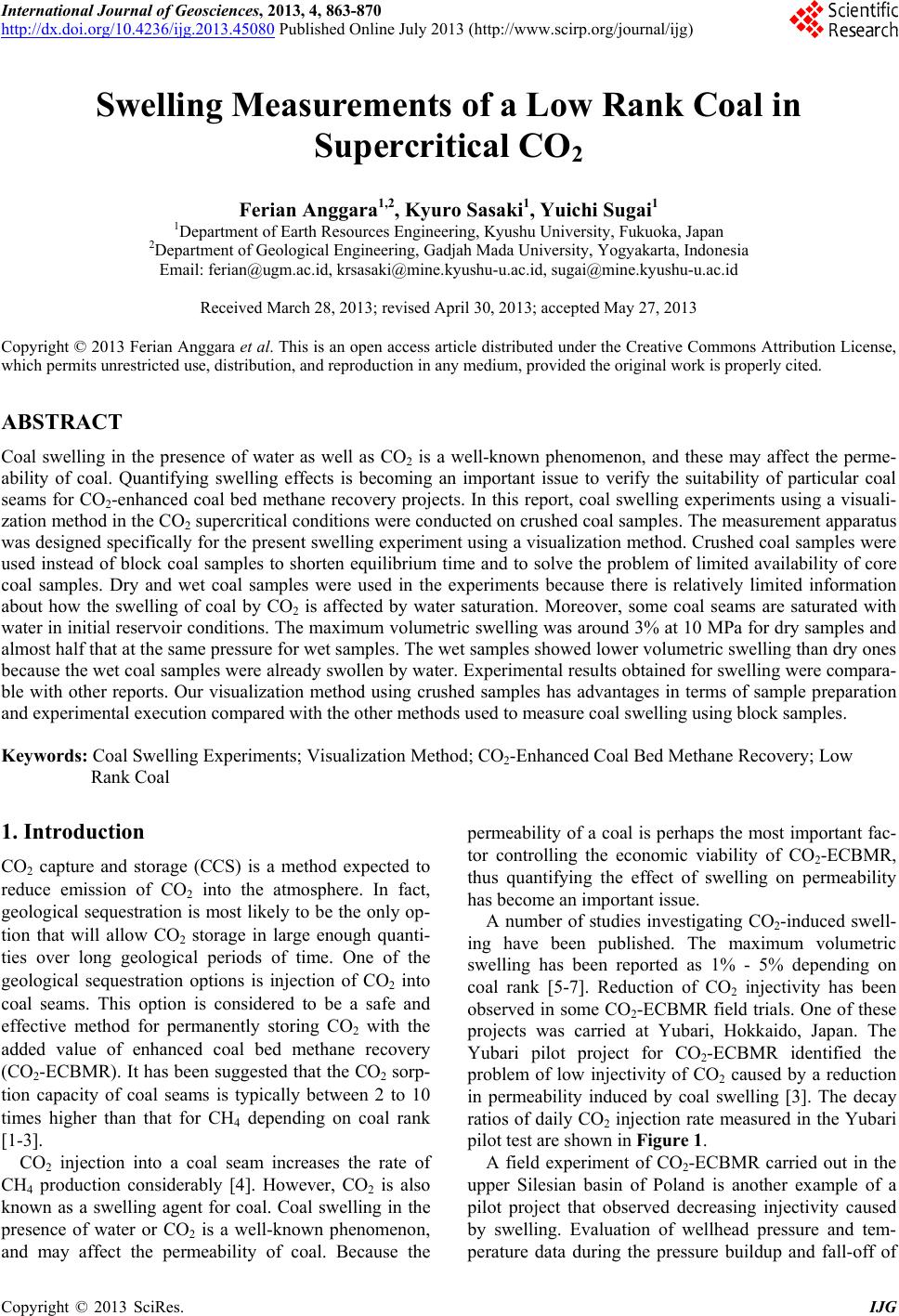
|