Paper Menu >>
Journal Menu >>
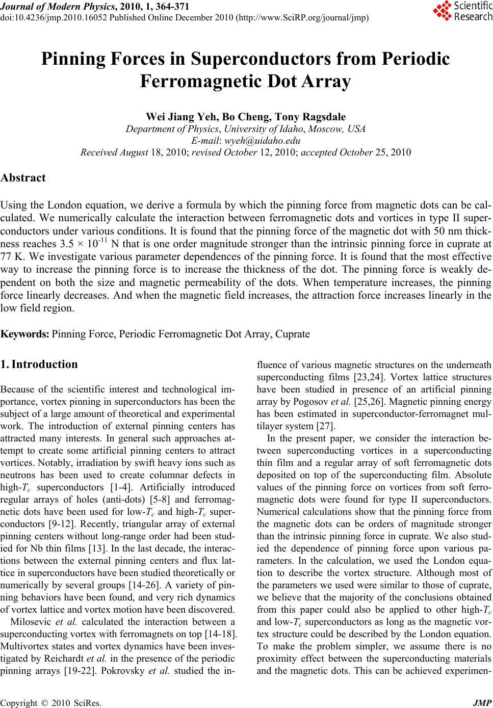 Journal of Modern Physics, 2010, 1, 364-371 doi:10.4236/jmp.2010.16052 Published Online December 2010 (http://www.SciRP.org/journal/jmp) Copyright © 2010 SciRes. JMP Pinning Forces in Superconductors from Periodic Ferromagnetic Dot Array Wei Jiang Yeh, Bo Cheng, Tony Ragsdale Department of Physics, University of Idaho, Moscow, USA E-mail: wyeh@uidaho.edu Received August 18, 2010; revised October 12, 2010; accepted October 25, 2010 Abstract Using the London equation, we derive a formula by which the pinning force from magnetic dots can be cal- culated. We numerically calculate the interaction between ferromagnetic dots and vortices in type II super- conductors under various conditions. It is found that the pinning force of the magnetic dot with 50 nm thick- ness reaches 3.5 × 10⁻¹¹ N that is one order magnitude stronger than the intrinsic pinning force in cuprate at 77 K. We investigate various parameter dependences of the pinning force. It is found that the most effective way to increase the pinning force is to increase the thickness of the dot. The pinning force is weakly de- pendent on both the size and magnetic permeability of the dots. When temperature increases, the pinning force linearly decreases. And when the magnetic field increases, the attraction force increases linearly in the low field region. Keywords: Pinning Force, Periodic Ferromagnetic Dot Array, Cuprate 1. Introduction Because of the scientific interest and technological im- portance, vortex pinning in superconductors has been the subject of a large amount of theoretical and experimental work. The introduction of external pinning centers has attracted many interests. In general such approaches at- tempt to create some artificial pinning centers to attract vortices. Notably, irradiation by swift heavy ions such as neutrons has been used to create columnar defects in high-Tc superconductors [1-4]. Artificially introduced regular arrays of holes (anti-dots) [5-8] and ferromag- netic dots have been used for low-Tc and high-Tc super- conductors [9-12]. Recently, triangular array of external pinning centers without long-range order had been stud- ied for Nb thin films [13]. In the last decade, the interac- tions between the external pinning centers and flux lat- tice in superconductors have been studied theoretically or numerically by several groups [14-26]. A variety of pin- ning behaviors have been found, and very rich dynamics of vortex lattice and vortex motion have been discovered. Milosevic et al. calculated the interaction between a superconducting vortex with ferromagnets on top [14-18]. Multivortex states and vortex dynamics have been inves- tigated by Reichardt et al. in the presence of the periodic pinning arrays [19-22]. Pokrovsky et al. studied the in- fluence of various magnetic structures on the underneath superconducting films [23,24]. Vortex lattice structures have been studied in presence of an artificial pinning array by Pogosov et al. [25,26]. Magnetic pinning energy has been estimated in superconductor-ferromagnet mul- tilayer system [27]. In the present paper, we consider the interaction be- tween superconducting vortices in a superconducting thin film and a regular array of soft ferromagnetic dots deposited on top of the superconducting film. Absolute values of the pinning force on vortices from soft ferro- magnetic dots were found for type II superconductors. Numerical calculations show that the pinning force from the magnetic dots can be orders of magnitude stronger than the intrinsic pinning force in cuprate. We also stud- ied the dependence of pinning force upon various pa- rameters. In the calculation, we used the London equa- tion to describe the vortex structure. Although most of the parameters we used were similar to those of cuprate, we believe that the majority of the conclusions obtained from this paper could also be applied to other high-Tc and low-Tc superconductors as long as the magnetic vor- tex structure could be described by the London equation. To make the problem simpler, we assume there is no proximity effect between the superconducting materials and the magnetic dots. This can be achieved experimen- 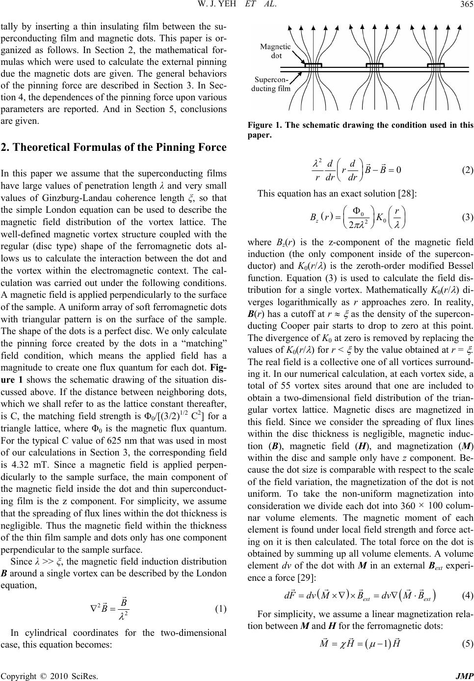 W. J. YEH ET AL.365 tally by inserting a thin insulating film between the su- perconducting film and magnetic dots. This paper is or- ganized as follows. In Section 2, the mathematical for- mulas which were used to calculate the external pinning due the magnetic dots are given. The general behaviors of the pinning force are described in Section 3. In Sec- tion 4, the dependences of the pinning force upon various parameters are reported. And in Section 5, conclusions are given. 2. Theoretical Formulas of the Pinning Force In this paper we assume that the superconducting films have large values of penetration length λ and very small values of Ginzburg-Landau coherence length ξ, so that the simple London equation can be used to describe the magnetic field distribution of the vortex lattice. The well-defined magnetic vortex structure coupled with the regular (disc type) shape of the ferromagnetic dots al- lows us to calculate the interaction between the dot and the vortex within the electromagnetic context. The cal- culation was carried out under the following conditions. A magnetic field is applied perpendicularly to the surface of the sample. A uniform array of soft ferromagnetic dots with triangular pattern is on the surface of the sample. The shape of the dots is a perfect disc. We only calculate the pinning force created by the dots in a “matching” field condition, which means the applied field has a magnitude to create one flux quantum for each dot. Fig- ure 1 shows the schematic drawing of the situation dis- cussed above. If the distance between neighboring dots, which we shall refer to as the lattice constant thereafter, is C, the matching field strength is Φ0/[(3/2)1/2 C2] for a triangle lattice, where Φ0 is the magnetic flux quantum. For the typical C value of 625 nm that was used in most of our calculations in Section 3, the corresponding field is 4.32 mT. Since a magnetic field is applied perpen- dicularly to the sample surface, the main component of the magnetic field inside the dot and thin superconduct- ing film is the z component. For simplicity, we assume that the spreading of flux lines within the dot thickness is negligible. Thus the magnetic field within the thickness of the thin film sample and dots only has one component perpendicular to the sample surface. Since λ >> ξ, the magnetic field induction distribution B around a single vortex can be described by the London equation, 2 2 B B (1) In cylindrical coordinates for the two-dimensional case, this equation becomes: Figure 1. The schematic drawing the condition used in this paper. 2 0 dd rBB rdr dr (2) This equation has an exact solution [28]: 0 0 2 2 z r Br K (3) where Bz(r) is the z-component of the magnetic field induction (the only component inside of the supercon- ductor) and K0(r/ ) is the zeroth-order modified Bessel function. Equation (3) is used to calculate the field dis- tribution for a single vortex. Mathematically K0(r/ ) di- verges logarithmically as r approaches zero. In reality, B(r) has a cutoff at r as the density of the supercon- ducting Cooper pair starts to drop to zero at this point. The divergence of K0 at zero is removed by replacing the values of K0(r/ ) for r < by the value obtained at r = . The real field is a collective one of all vortices surround- ing it. In our numerical calculation, at each vortex side, a total of 55 vortex sites around that one are included to obtain a two-dimensional field distribution of the trian- gular vortex lattice. Magnetic discs are magnetized in this field. Since we consider the spreading of flux lines within the disc thickness is negligible, magnetic induc- tion (B), magnetic field (H), and magnetization (M) within the disc and sample only have z component. Be- cause the dot size is comparable with respect to the scale of the field variation, the magnetization of the dot is not uniform. To take the non-uniform magnetization into consideration we divide each dot into 360 × 100 colum- nar volume elements. The magnetic moment of each element is found under local field strength and force act- ing on it is then calculated. The total force on the dot is obtained by summing up all volume elements. A volume element dv of the dot with M in an external Bext experi- ence a force [29]: ext ext dFdv MBdvMB (4) For simplicity, we assume a linear magnetization rela- tion between M and H for the ferromagnetic dots: 1 M H H (5) Copyright © 2010 SciRes. JMP 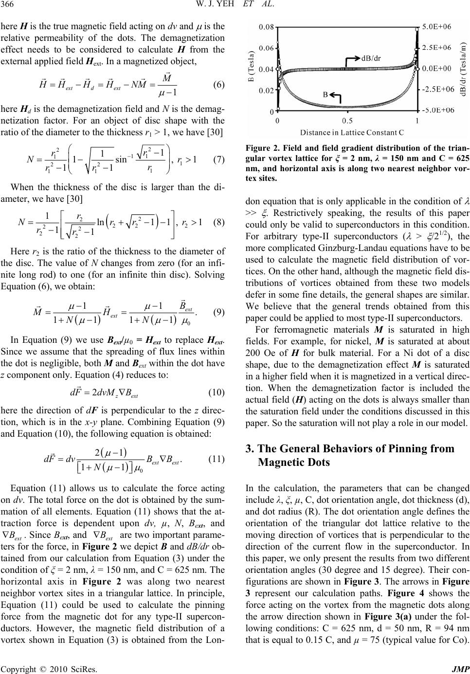 W. J. YEH ET AL. 366 here H is the true magnetic field acting on dv and is the relative permeability of the dots. The demagnetization effect needs to be considered to calculate H from the external applied field Hext. In a magnetized object, 1 ext dext M HHH HNM (6) here Hd is the demagnetization field and N is the demag- netization factor. For an object of disc shape with the ratio of the diameter to the thickness r1 > 1, we have [30] 2 2 1 1 1 1 22 1 11 1 1 1sin , 11 r r N r rr 1r (7) When the thickness of the disc is larger than the di- ameter, we have [30] 2 2 22 2 22 22 1ln11, 1 11 r Nrr rr r (8) Here r2 is the ratio of the thickness to the diameter of the disc. The value of N changes from zero (for an infi- nite long rod) to one (for an infinite thin disc). Solving Equation (6), we obtain: 0 11 . 1111 ext ext B MH NN (9) In Equation (9) we use Bext/µ0 = Hext to replace Hext. Since we assume that the spreading of flux lines within the dot is negligible, both M and Bext within the dot have z component only. Equation (4) reduces to: 2 z ext dFdvM B (10) here the direction of dF is perpendicular to the z direc- tion, which is in the x-y plane. Combining Equation (9) and Equation (10), the following equation is obtained: 0 21 . 11 ext ext dF dvBB N (11) Equation (11) allows us to calculate the force acting on dv. The total force on the dot is obtained by the sum- mation of all elements. Equation (11) shows that the at- traction force is dependent upon dv, µ, N, Bext, and ext . Since Bext, and ext are two important parame- ters for the force, in Figure 2 we depict B and dB/dr ob- tained from our calculation from Equation (3) under the condition of ξ = 2 nm, λ = 150 nm, and C = 625 nm. The horizontal axis in Figure 2 was along two nearest neighbor vortex sites in a triangular lattice. In principle, Equation (11) could be used to calculate the pinning force from the magnetic dot for any type-II supercon- ductors. However, the magnetic field distribution of a vortex shown in Equation (3) is obtained from the Lon- BB Figure 2. Field and field gradient distribution of the trian- gular vortex lattice for ξ = 2 nm, λ = 150 nm and C = 625 nm, and horizontal axis is along two nearest neighbor vor- tex sites. don equation that is only applicable in the condition of >> . Restrictively speaking, the results of this paper could only be valid to superconductors in this condition. For arbitrary type-II superconductors ( > /21/2), the more complicated Ginzburg-Landau equations have to be used to calculate the magnetic field distribution of vor- tices. On the other hand, although the magnetic field dis- tributions of vortices obtained from these two models defer in some fine details, the general shapes are similar. We believe that the general trends obtained from this paper could be applied to most type-II superconductors. For ferromagnetic materials M is saturated in high fields. For example, for nickel, M is saturated at about 200 Oe of H for bulk material. For a Ni dot of a disc shape, due to the demagnetization effect M is saturated in a higher field when it is magnetized in a vertical direc- tion. When the demagnetization factor is included the actual field (H) acting on the dots is always smaller than the saturation field under the conditions discussed in this paper. So the saturation will not play a role in our model. 3. The General Behaviors of Pinning from Magnetic Dots In the calculation, the parameters that can be changed include λ, ξ, µ, C, dot orientation angle, dot thickness (d), and dot radius (R). The dot orientation angle defines the orientation of the triangular dot lattice relative to the moving direction of vortices that is perpendicular to the direction of the current flow in the superconductor. In this paper, we only present the results from two different orientation angles (30 degree and 15 degree). Their con- figurations are shown in Figure 3. The arrows in Figure 3 represent our calculation paths. Figure 4 shows the force acting on the vortex from the magnetic dots along the arrow direction shown in Figure 3(a) under the fol- lowing conditions: C = 625 nm, d = 50 nm, R = 94 nm that is equal to 0.15 C, and µ = 75 (typical value for Co). Copyright © 2010 SciRes. JMP 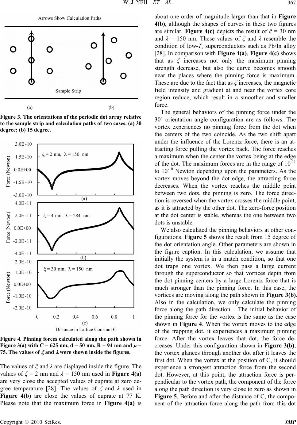 W. J. YEH ET AL.367 (a) (b) Figure 3. The orientations of the periodic dot array relative to the sample strip and calculation paths of two cases. (a) 30 degree; (b) 15 degree. Figure 4. Pinning forces calculated along the path shown in Figure 3(a) with C = 625 nm, d = 50 nm, R = 94 nm and µ = 75. The values of and were shown inside the figures. The values of ξ and λ are displayed inside the figure. The values of ξ = 2 nm and λ = 150 nm used in Figure 4(a) are very close the accepted values of cuprate at zero de- gree temperature [28]. The values of ξ and λ used in Figure 4(b) are close the values of cuprate at 77 K. Please note that the maximum force in Figure 4(a) is about one order of magnitude larger than that in Figure 4(b), although the shapes of curves in these two figures are similar. Figure 4(c) depicts the result of ξ = 30 nm and λ = 150 nm. These values of ξ and λ resemble the condition of low-Tc superconductors such as Pb/In alloy [28]. In comparison with Figure 4(a), Figure 4(c) shows that as ξ increases not only the maximum pinning strength decrease, but also the curve becomes smooth near the places where the pinning force is maximum. These are due to the fact that as ξ increases, the magnetic field intensity and gradient at and near the vortex core region reduce, which result in a smoother and smaller force. The general behaviors of the pinning force under the 30˚ orientation angle configuration are as follows. The vortex experiences no pinning force from the dot when the centers of the two coincide. As the two shift apart under the influence of the Lorentz force, there is an at- tracting force pulling the vortex back. The force reaches a maximum when the center the vortex being at the edge of the dot. The maximum forces are in the range of 10-11 to 10-10 Newton depending upon the parameters. As the vortex moves beyond the dot edge, the attracting force decreases. When the vortex reaches the middle point between two dots, the pinning is zero. The force direc- tion is reversed when the vortex crosses the middle point, as it is attracted by the other dot. The zero-force position at the dot center is stable, whereas the one between two dots is unstable. We also calculated the pinning behaviors at other con- figurations. Figure 5 shows the result from 15 degree of the dot orientation angle. Other parameters are shown in the figure caption. In this calculation, we assume that initially the system is in a match condition, so that one dot traps one vortex. We then pass a large current through the superconductor so that vortices depin from the dot pinning centers by a large Lorentz force that is much stronger than the pinning force. In this case, the vortices are moving along the path shown in Figure 3(b). Also in the calculation, we only calculate the pinning force along the path direction. The initial behavior of the pinning force for the vortex is the same as the case shown in Figure 4. When the vortex moves to the edge of the trapping dot, it experiences a maximum pinning force. After the vortex leaves that dot, the force de- creases. Under this configuration shown in Figure 3(b), the vortex glances through another dot after it leaves the first dot. When the vortex at the position of C, it should experience a strongest attraction force from the second dot. However, at this point, the attraction force is per- pendicular to the vortex path, the component of the force along the path direction is very close to zero as shown in Figure 5. Before and after the distance of C, the compo- nent of the attraction force along the path from this dot Copyright © 2010 SciRes. JMP  W. J. YEH ET AL. 368 Figure 5. Pinning force calculated along the path shown in Figure 3(b) with ξ = 2 nm, λ = 150 nm, C = 625 nm, d = 50 nm, R = 94 nm and µ = 75. should not be zero, which is consistent with the calcula- tion result shown in Figure 5. After the vortex moves into an open space, we expect that it only experiences very little force from surrounding dots, which is also consistent with the calculation as shown in the figure. If the current is just above the critical current of the sample, the Lorentz force is comparable with the pinning force. The vortex may not move in a straight path as shown in Figure 3(b). Instead, it may move in a zigzag path under the influence of the Lorentz, pinning, and repulsing forces between vortices [22]. This case is beyond the scope of this paper. The maximum strength of internal pinning force of a superconductor can be estimated from its critical current density: int dτ FJB (12) A typical Jc of a high quality YBa2Cu3O7-δ (YBCO) thin film at 77 K is about 106 A/cm2. For a sample thick- ness t = 200 nm, Fint = Jc Φ0 t = 4 × 10-12 N. Notice that the maximum strength of external pinning force we ob- tained from the magnetic dot in the situation of cuprate at 77 K is 3.4 × 10⁻¹¹ N for a dot thickness of 50 nm, which is about one order of magnitude higher than the intrinsic pinning force. This means that the magnetic dots depos- ited on the surface will have a stronger ability to hold the vortices in place than the internal pinning centers. 4. The Dependence of the Attraction Force upon Various Parameters Since in this paper we mainly concentrate on the magni- tude of the attraction force from the magnetic dot, all the results reported below are the maximum value obtained under the configuration shown in Figure 3(a) . The dependence of force upon the thickness of the dot is shown in Figure 6. In this calculation, other parame- ters were ξ = 2 nm, λ = 150 nm, µ = 75, C = 625 nm, and R = 0.15 C. As the thickness of the dot increases, the pinning should also increase because the volume of the ferromagnetic materials increases. The volume depend- ent increase should be linear. The non-linear dependence of force upon the thickness shown in Figure 6 originates from the volume dependence plus the demagnetization effect. As the thickness increases, the demagnetization factor N reduces, which also enhances the pinning force. Here we quote a few specific values of the forces. When the thicknesses of the dot are 50 nm, 100 nm and 200 nm, the attraction forces are 2.3 × 10⁻¹⁰ N, 6.1 × 10⁻¹⁰ N and 1.9 × 10⁻⁹ N, respectively. It shows that when the thick- ness of the dot doubles the force increases about three- fold. We then calculated the dot size dependence, which is shown in Figure 7. In this calculation, we used ξ as a parameter that is shown in the figure. Other parameters were λ = 150 nm, C = 625 nm, d = 50 nm and µ = 75. We can draw three conclusions from the figure. First, the figure shows that as the coherence length increases, the attraction force decreases. Second, all curves in Figure 7 have a plateau region from about R = 50 nm to R = 230 Figure 6. The dependence of the maximum pinning force upon the thickness of the dot under the condition of ξ = 2 nm, λ = 150 nm, C = 625 nm, R = 94 nm and µ = 75. Figure 7. The dependence of the maximum pinning force upon the size of the dot for three values of . Other pa- rameters were λ = 150 nm, C = 625 nm, d = 50 nm and µ = 75. Copyright © 2010 SciRes. JMP  W. J. YEH ET AL.369 nm. In this region, the strength of the attraction varies little. When R is larger than 230 nm the attraction force decreases. This decrease is due to the restriction from the lattice constant C. In the calculation, we chose C = 625 nm. When R is approaching 300 nm, the two adjacent dots are very close. In this case, when a vortex moves to the edge of the first dot, it experiences a maximum at- traction from this dot to pull it back. At the same time, due to the large value of the penetration length, part of the vortex is already in the region occupied by the sec- ond dot. The second dot also exerts a force on that vortex. This is opposite to the first one, so that the total force reduces. If we use a larger lattice constant, the plateau region will extend farther to the right. Third, as the dot size decreases below 100 nm, the forces show different behaviors for different coherent lengths. When the dot size reduces two different factors are at work. Number one is that when the dot size reduces the demagnetization factor reduces, which increases the force. Number two is the mass of the dot. As the size of dot reduces, the fer- romagnetic materials reduces, which results in a smaller force. It seems that for small coherence length (ξ = 2 nm) the demagnetization effect dominates. On the other hand, for relatively large coherence length (ξ = 10 nm) the mass effect dominates. When the coherence length is 5 nm, the force is almost constant when the dot size re- duces. We need to point out that the coherence length of cuprate at 77 K is about 4 nm, which is very close to 5 nm. It means that if we want to use ferromagnetic dot as the external pinning for cuprate at 77 K, the dot size is not a factor. Almost any size of dot will give the similar pinning force. We also studied the force dependence upon the mag- netic permeability µ. The µ dependence is in the pre-factor in Equation (11), which is (µ − 1)/[1 + N(µ − 1)]. In general, as µ decreases, the attraction force is also reduced. The relationship between the force and µ is also dependent upon the value of N. If N is zero in case of an infinite long dot, then the force is proportional to (µ − 1). The force is approximately proportional to µ, except when µ is close to one. On the other hand, if N is 1 in case of an infinite thin dot, the force is proportional to (µ − 1)/µ. The force is weakly dependent upon µ until µ is close to one. Since in reality we do not have these ex- treme conditions, we selected two cases to carry out the calculation of the µ dependence. In case A, the thickness of the dot was 50 nm and the value of N is 0.689. In case B, the thickness of the dot was 500 nm and N equals to 0.125. In both cases, other parameters were ξ = 2 nm, λ = 150 nm, C = 625 nm, and R = 94 nm. The results are depicted in Figure 8. For both cases, when the value of µ decreases from 100, the attraction force for both cases decreases in a slow pace until µ reaches 25. After that Figure 8. The dependence of the maximum pinning force upon the magnetic permeability µ for d = 50 nm and d = 500 nm, respectively. Other parameters were ξ = 2 nm, λ = 150 nm, C = 625 nm and R = 94 nm. point the attraction force decreases dramatically. The average initial values of µ for iron, cobalt and nickel are 150, 70 and 110, respectively [31]. All of them are much higher than 25. Our result indicates that when choosing ferromagnetic materials working as external pinning, the µ value is not an important factor. We also investigated the temperature dependence of the attraction force. In this study, we assumed the ferro- magnetic properties of dots did not change. We also as- sumed that the ferromagnetic dots were deposited on a cuprate thin film. The lengths of ξ and λ of the vortex in the thin film change when the temperature changes. We used the Ginzburg-Landau theory to calculate the values of ξ and λ at different temperatures. Since the theory is only valid when the temperatures are close the transition temperature (Tc), besides zero degree we only calculated a few points near Tc of cuprate, which we assume to be 90 K. At zero degree we used ξ0 = 2 nm and λ0 = 150 nm. The formulas we used to calculate ξ and λ at other tem- peratures were ξ(t) = 0.74ξ0/(1 − t)1/2 and λ(t) = λ0/[2(1 − t)]1/2, which are the relations in the clean limit [32]. In the calculation, other parameters were C = 625 nm, d = 50 nm, R = 0.15 C, and µ = 75. The result is shown in Figure 9. It shows that the attraction force almost line- arly decreases as the temperature increases. Finally, we studied the magnetic field strength de- pendence of the attraction force. As the field strength increases, the vortex density increases and the field strength at any place also enhances. As shown in Equa- tion (11), the attraction force should be proportional to the external field strength. To confirm this, we carried a numerical calculation. In the calculation, we used the following parameters: λ = 284 nm, = 4 nm, R = 40 nm, d = 50 nm and µ = 75. The values of λ and ξ used in this calculation resemble the values for cuprate at 77 K. In the calculation, as the field strength changed, the density of dots was also changed so that the matching condition was always maintained. Figure 10 shows the result. It Copyright © 2010 SciRes. JMP  W. J. YEH ET AL. 370 Figure 9. The temperature dependence of the maximum pinning force. The values of and at different tempera- tures were obtained from the Ginzburg-Landau theory under the clean limit of cuprate. Other parameters were C = 625 nm, d = 50 nm, R = 0.15 C, and µ = 75. Figure 10. The magnetic field dependence of the maximum pinning force under the condition of λ = 284 nm, = 4 nm, R = 40 nm, d = 50 nm and µ = 75. At any magnetic field, the value of C was determined under the matching co ndition. shows that in low fields the attraction force linearly in- creases as the field strength increases as expected. This is consistent with the experimental observation [12]. Ref- erence [12] showed that when the magnetic field was increased the pinning effect from magnetic dots also en- hanced. As the magnetic field passes 40 mT, the curve then starts to deviate from the linear behavior. The in- crease slows down. When the magnetic field equals 40 mT, the value of C equals 205 nm. Because of the large value of λ we used (λ = 284 nm), when the vortex moves to the edge of the dot where the attraction reaches the maximum, part of the vortex already feel the opposite attraction from the adjacent magnetic dot, which results in a smaller total force. This is the reason why at high fields, the increase slows down from a linear relation. 5. Conclusions We have developed a theoretical model to describe the interactions between the magnetic dots and vortices in the superconductor by using the London equation. The absolute values of the pinning force under various condi- tions have been calculated. The external attraction force from a soft ferromagnetic dot with a thickness of 50 nm could reach 3.5 × 10⁻¹¹ N for a cuprate sample at 77 K, which is about one order of magnitude stronger than the intrinsic pinning force in cuprate. We also studied the dependences of the attraction force on various parame- ters. We found that the most effective way to increase the external pinning force is to increase the thickness of dot. When the thickness doubles, the force increases about threefold. On the other hand, in a large range of the dot size, the force remains approximately constant. We found that the pining force is weakly dependent upon the value of µ. We also investigated the temperature and magnetic field dependences of the force. When tempera- ture increases, the attraction force linearly decreases. And when the magnetic field increases, the force en- hances linearly in the low field region. 6. Acknowledgments This work was partly supported by NSF grant PHY- 0754360. 7. References [1] F. M. Sauerzopf, H. P. Wiesinger, H. W. Weber, G. W. Crabtree and J. Z. Liu, “Magnetization of Neutron Irradi- ated YBa2Cu3O7-δ Single Crystals,” Physica C, Vol. 162-164, 1989, pp. 751-752. [2] L. Civale, A. D. Marwick, T. K. Worthington, M. A. Kirk, J. R. Thompson, L. Krusin-elbaum, Y. Sun, J. R. Clem and F. Holtzberg, “Vortex Confinement by Columnar Defects in YBa2Cu3O7 Crystals: Enhanced Pinning at High Fields and Temperatures,” Physical Review Letters, Vol. 67, No. 5, 1991, pp. 648-561. [3] J. R. Thompson, L. Krusin-Elbaum and D. K. Christen, “Current-density Enhancements of the Highest-Tc Super- conductors with GeV Protons,” Applied Physics Letters, Vol. 71, No. 4, 1997, pp. 536-538. [4] T. Kato, T. Shibauchi, Y. Matsuda, J. R. Thompson and L. Krusin-Elbaum, “Interlayer Coherence in Bi2Sr2CaCu2O8+y with Splayed Columnar Defects,” Physica C, Vol. 463- 465, 2007, pp. 240-244. [5] M. Baert, V. V. Metlushko, R. Jonckheere, V. V. Mosh- chalkov and Y. Bruynseraede, “Composite Flux-line Lat- tices Stabilized in Superconducting Films by a Regular Array of Artificial Defects,” Physical Review Letters, Vol. 74, No. 16, 1995, pp. 3269-3272. [6] E. Rosseel, T. Puig, M. Baert, M. J. Van Bael, V. V. Moshchalkov and Y. Bruynseraede, “Upper Critical Field of Pb Films with an Antidot Lattice,” Physica C, Vol. 282-287, 1997, pp. 1567-1568. Copyright © 2010 SciRes. JMP  W. J. YEH ET AL. Copyright © 2010 SciRes. JMP 371 [7] A. V. Silhanek, L. V. Look, R. Jonckheere, B. Y. Zhu, S. Raedts and V. V. Moshchalkov, “Enhanced Vortex Pin- ning by a Composite Antidot Lattice in a Superconduct- ing Pb Film,” Physical Review B, Vol. 72, No. 1, 2005, pp. 1-6. [8] S. L. Prischepa, A. A. Armenio, L. Maritato, V. N. Kush- nir and S. Barbanera, “The Influence of a Submicrometre Antidot Array on the Vortex Topology and the Pinning Mechanism in Layered Superconductors”, Superconduc- tor Science and Technology, Vol. 18, No. 1, 2005, pp. 152-157. [9] J. I. Martin, M. Velez, J. Nogues and I. K. Schuller, “Flux Pinning in a Superconductor by an Array of Submicro- meter Magnetic Dot,” Physical Review Letters, Vol. 79, No. 10, 1997, pp. 1929-1932. [10] D. J. Morgan and J. B. Ketterson, “Asymmetric Flux Pinning in a Regular Array of Magnetic Dipoles,” Physi- cal Review Letters, Vol. 80, No. 16, 1998, pp. 3614-3617. [11] M. Lange, M. J. V. Bael, Y. Bruynseraede and V. V. Moshchalkov, “Nanoengineered Magnetic-Field-Induced Superconductivity,” Physical Review Letters, Vol. 90, No. 19, 2003, pp. 1-4. [12] W. J. Yeh, B. Cheng and B. L. Justus, “I–V Characteris- tics of YBCO Thin Films with a Periodic Array of Ni Dots,” Physica C, Vol. 388-389, 2003, pp. 433-434. [13] J. Eisenmenger, M. Oettinger, C. Pfahler, A. Plettl and P. Ziemann, “Temperature-dependent Matching in a Flux-line Lattice Interacting with a Triangular Array of Pinning Centers without Long-range Order,” Physical Review B, Vol. 75, No. 14, 2007, p. 144514. [14] M. V. Milosevic and F. M. Peeters, “Vortex-Antivortex Lattices in Superconducting Films with Magnetic Pinning Arrays,” Physical Review Letters, Vol. 93, No. 26, 2004, p. 267006. [15] M. V. Milosevic and F. M. Peeters, “Vortex Pinning in a Superconducting Film Due to In-plane Magnetized Fer- romagnets of Different Shapes: The London Approxima- tion,” Physical Review B, Vol. 69, No. 10, 2004, p. 104522. [16] M. V. Milosevic and F. M. Peeters, “Field-enhanced Critical Parameters in Magnetically Nanostructured Su- perconductors,” Europhysics Letters, Vol. 70, No. 5, 2005, pp. 670-676. [17] M. V. Milosevic and F. M. Peeters, “Interaction between a Superconducting Vortex and an Out-of-plane Magnet- ized Ferromagnetic Disk: Influence of the Magnet Ge- ometry,” Physical Review B, Vol. 68, No. 9, 2003, pp. 094510. [18] M. V. Milosevic and F. M. Peeters, “Vortex-Antivortex Lattices in Superconducting Films with Magnetic Pinning Arrays,” Journal of Low Temperature Physics, Vol. 139, No. 1, 2005, pp. 257-272. [19] C. Reichhardt, C. J. Olson and F. Nori, “Nonequilibrium Dynamic Phases and Plastic Flow of Driven Vortex Lat- tices in Superconductors with Periodic Arrays of Pinning Sites,” Physical Review B, Vol. 58, No. 10, 1998, pp. 6534-6564. [20] C. Reichhardt and N. Gronbech-Jensen, “Collective Mul- tivortex States in Periodic Arrays of Traps,” Physical Re- view Letters, Vol. 85, No. 11, 2000, pp. 2372-2375. [21] C. Reichhardt, G. T. Zimanyi, R. T. Scalettar, A. Hoff- mann and I. K. Schuller, “Individual and Multiple Vortex Pinning in Systems with Periodic Pinning Arrays,” Phys- ical Review B, Vol. 64, No. 5, 2001, p. 052503. [22] C. Reichhardt and C. J. O. Reichhardt, “Ratchet Effects for Vortices in Superconductors with Periodic Pinning Arrays,” Physica C, Vol. 404, No. 1-4, 2004, pp. 302-305. [23] I. F. Lyuksyutov and V. Pokrovsky, “Magnetization Con- trolled Superconductivity in a Film with Magnetic Dots,” Physical Review Letters, Vol. 81, No. 11, 1998, pp. 2344-2347. [24] S. Erdin, F. Kayali, I. F. Lyuksyutov and V. Pokrovsky, “Interaction of Mesoscopic Magnetic Textures with Su- perconductors,” Physical Review B, Vol. 66, No. 1, 2002. [25] W. V. Pogosov, A. L. Rakhmanov and V. V. Mosh- chalkov, “Vortex Lattice in the Presence of a Tunable Pe- riodic Pinning Potential,” Physical Review B, Vol. 67, No. 1, 2003, p. 014532. [26] W. V. Pogosov and V. V. Moshchalkov, “Vortex Lattice Structure in Presence of an Artificial Periodic Pinning Array,” Physica C, Vol. 404, No. 1-4, 2004, pp. 285-288. [27] L. N. Bulaevskii, E. M. Chudnovsky and M. P. Maley, “Magnetic Pinning in Superconductor-ferromagnet Mul- tilayers,” Applied Physics Letters, Vol. 76, No. 18, 2000, pp. 2594-2596. [28] C. P. Poole, H. A. Farach and R. J. Creswick, “Super- conductivity,” Academic Press, California, 1995. [29] J. D. Jackson, “Classical Electrodynamics,” 3rd Edition, John Wiley & Sons Ltd., Chichester, 1999. [30] B. D. Cullity, “Introduction to Magnetic Materials,” Ad- dison-Wesley Publishing Company, Massachusetts, 1972. [31] E. U. Condon and H. Odishaw, “Handbook of Physics,” 2nd Edition, McGraw-Hill Book Company, New York, 1967. [32] M. Tinkham, “Introduction to Superconductivity,” Mc- Graw-Hill Book Company, New York, 1975. |