Paper Menu >>
Journal Menu >>
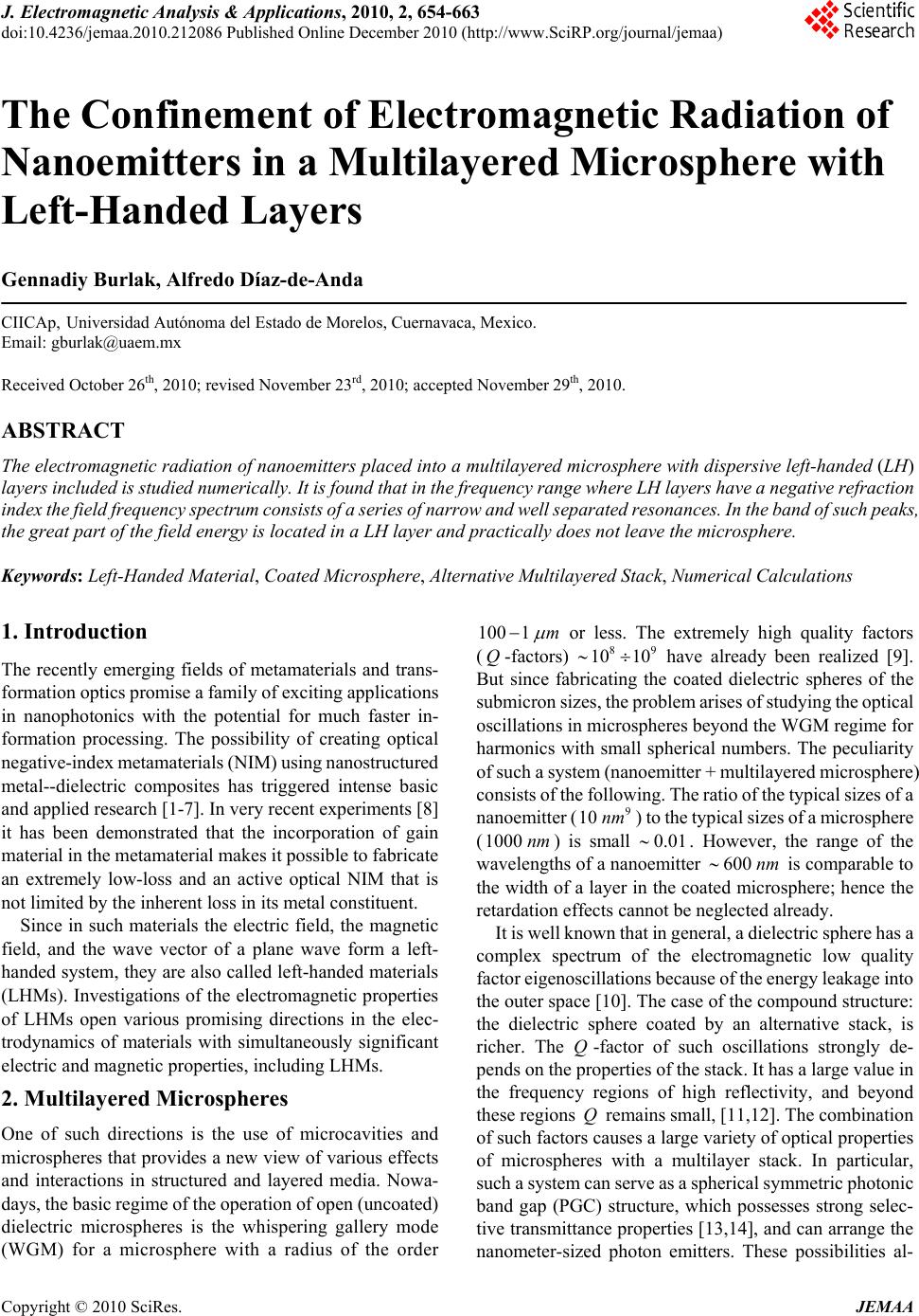 J. Electromagnetic Analysis & Applications, 2010, 2, 654-663 doi:10.4236/jemaa.2010.212086 Published Online December 2010 (http://www.SciRP.org/journal/jemaa) Copyright © 2010 SciRes. JEMAA The Confinement of Electromagnetic Radiation of Nanoemitters in a Multilayered Microsphere with Left-Handed Layers Gennadiy Burlak, Alfredo Díaz-de-Anda CIICAp, Universidad Autónoma del Estado de Morelos, Cuernavaca, Mexico. Email: gburlak@uaem.mx Received October 26th, 2010; revised November 23rd, 2010; accepted November 29th, 2010. ABSTRACT The electromagnetic rad iation of nanoemitters pla ced into a multila yered microsphere with dispersive left-han ded (LH) layers included is studie d num erically . It is fo und that in the frequency r ange w here LH lay ers have a n egative ref raction index the fiel d frequency spectrum c onsists of a series of narrow and w ell separated reso nances. In the band of such peaks, the great part of the field energy is loca ted in a LH layer and practically does not leave the microsphere. Keywords: Left-Handed Material, Coated Microsphere, Alternative Multilayered Stack, Numerical Calculations 1. Introduction The recently emerging fields of metamaterials and trans- formation optics promise a family of exciting applications in nanophotonics with the potential for much faster in- formation processing. The possibility of creating optical negative-index metamaterials (NIM) using nanostructured metal--dielectric composites has triggered intense basic and applied research [1-7]. In very recent experiments [8] it has been demonstrated that the incorporation of gain material in the metamaterial makes it possible to fabricate an extremely low-loss and an active optical NIM that is not limited by the inherent loss in its metal constituent. Since in such materials the electric field, the magnetic field, and the wave vector of a plane wave form a left- handed system, they are also called left-handed materials (LHMs). Investigations of the electromagnetic properties of LHMs open various promising directions in the elec- trodynamics of materials with simultaneously significant electric and magnetic properties, including LHMs. 2. Multilayered Microspheres One of such directions is the use of microcavities and microspheres that provides a new view of various effects and interactions in structured and layered media. Nowa- days, the basic regime of the operation of open (uncoated) dielectric microspheres is the whispering gallery mode (WGM) for a microsphere with a radius of the order 100 1m or less. The extremely high quality factors (Q-factors) have already been realized [9]. But since fabricating the coated dielectric spheres of the submicron sizes, the problem arises of studying the optical oscillations in microspheres beyond the WGM regime for harmonics with small spherical numbers. The peculiarity of such a system (nanoemitter + multilayered microsphere) consists of the following. The ratio of the typical sizes of a nanoemitter () to the typical sizes of a microsphere (100 ) is small 8 10 10 9 10 nm 0.0 9 0nm 1 . However, the range of the wavelengths of a nanoemitter is comparable to the width of a layer in the coated microsphere; hence the retardation effects cannot be neglected already. 600 nm It is well known that in general, a dielectric sphere has a complex spectrum of the electromagnetic low quality factor eigenoscillations because of the energy leakage into the outer space [10]. The case of the compound structure: the dielectric sphere coated by an alternative stack, is richer. The -factor of such oscillations strongly de- pends on the properties of the stack. It has a large value in the frequency regions of high reflectivity, and beyond these regions remains small, [11,12]. The combination of such factors causes a large variety of optical properties of microspheres with a multilayer stack. In particular, such a system can serve as a spherical symmetric photonic band gap (PGC) structure, which possesses strong selec- tive transmittance properties [13,14], and can arrange the nanometer-sized photon emitters. These possibilities al- Q Q 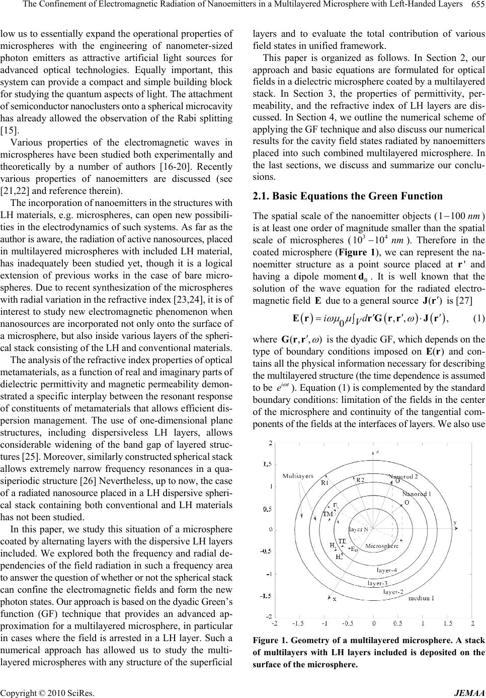 The Confinement of Electromagnetic Radiation of Nanoemitters in a Multilayered Microsphere with Left-Handed Layers 655 low us to essentially expand the operational properties of microspheres with the engineering of nanometer-sized photon emitters as attractive artificial light sources for advanced optical technologies. Equally important, this system can provide a compact and simple building block for studying the quantum aspects of light. The attachment of semiconductor nanoclusters onto a spherical microcavity has already allowed the observation of the Rabi splitting [15]. Various properties of the electromagnetic waves in microspheres have been studied both experimentally and theoretically by a number of authors [16-20]. Recently various properties of nanoemitters are discussed (see [21,22] and reference therein). The incorporation of nanoemitters in the structures with LH materials, e.g. microspheres, can open new possibili- ties in the electrodynamics of such systems. As far as the author is aware, the radiation of active nanosources, placed in multilayered microspheres with included LH material, has inadequately been studied yet, though it is a logical extension of previous works in the case of bare micro- spheres. Due to recent synthesization of the microspheres with radial variation in the refractive index [23,24], it is of interest to study new electromagnetic phenomenon when nanosources are incorporated not only onto the surface of a microsphere, but also inside various layers of the spheri- cal stack consisting of the LH and conventional materials. The analysis of the refractive index properties of optical metamaterials, as a function of real and imaginary parts of dielectric permittivity and magnetic permeability demon- strated a specific interplay between the resonant response of constituents of metamaterials that allows efficient dis- persion management. The use of one-dimensional plane structures, including dispersiveless LH layers, allows considerable widening of the band gap of layered struc- tures [25]. Moreover, similarly constructed spherical stack allows extremely narrow frequency resonances in a qua- siperiodic structure [26] Nevertheless, up to now, the case of a radiated nanosource placed in a LH dispersive spheri- cal stack containing both conventional and LH materials has not been studied. In this paper, we study this situation of a microsphere coated by alternating layers with the dispersive LH layers included. We explored both the frequency and radial de- pendencies of the field radiation in such a frequency area to answer the question of whether or not the spherical stack can confine the electromagnetic fields and form the new photon states. Our approach is based on the dyadic Green’s function (GF) technique that provides an advanced ap- proximation for a multilayered microsphere, in particular in cases where the field is arrested in a LH layer. Such a numerical approach has allowed us to study the multi- layered microspheres with any structure of the superficial layers and to evaluate the total contribution of various field states in unified framework. This paper is organized as follows. In Section 2, our approach and basic equations are formulated for optical fields in a dielectric microsphere coated by a multilayered stack. In Section 3, the properties of permittivity, per- meability, and the refractive index of LH layers are dis- cussed. In Section 4, we outline the numerical scheme of applying the GF technique and also discuss our numerical results for the cavity field states radiated by nanoemitters placed into such combined multilayered microsphere. In the last sections, we discuss and summarize our conclu- sions. 2.1. Basic Equations the Green Function The spatial scale of the nanoemitter objects (1100nm ) is at least one order of magnitude smaller than the spatial scale of microspheres (). Therefore in the coated microsphere (Figure 1), we can represent the na- noemitter structure as a point source placed at and having a dipole moment0. It is well known that the solution of the wave equation for the radiated electro- magnetic field due to a general source is [27] 34 1010 nm d'r ) E(Jr ,, , 0 id V ErrGrrJr (1) where (, , ) Grr it e is the dyadic GF, which depends on the type of boundary conditions imposed on and con- tains all the physical information necessary for describing the multilayered structure (the time dependence is assumed to be ()Er ). Equation (1) is complemented by the standard boundary conditions: limitation of the fields in the center of the microsphere and continuity of the tangential com- ponents of the fields at the interfaces of layers. We also use E Ø Figure 1. Geometry of a multilayered microsphere. A stack of multilayers with LH layers included is deposited on the surface of the microsphere. Copyright © 2010 SciRes. JEMAA 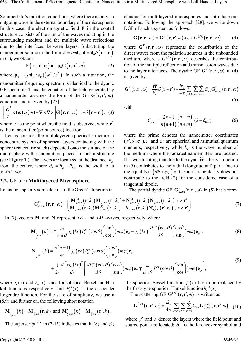 The Confinement of Electromagnetic Radiation of Nanoemitters in a Multilayered Microsphere with Left-Handed Layers Copyright © 2010 SciRes. JEMAA 656 ditions, where there is only an Sommerfeld’s radiation conchnique for multilayered microspheres and introduce our notations. Following the approach [28], we write down DGF of such a system as follows: outgoing wave in the external boundary of the microsphere. In this case, the electromagnetic field E in the coated structure consists of the sum of the waves radiating in the surrounding medium and the multiple wave reflections due to the interfaces between layers. Substituting the nanoemitter source in the form i Jd, 0 dd rr in (1), we obtain 0 ,,,, , r pGrr Er (2) where In such a itter frequency spectrum 22 000 //c pd situation, the nanoem is identical to the dyadic GF spectrum. Thus, the equation of the field generated by a nanoemitter assumes the form of the GF ,, Grr equation, and is given by [27] 2,, , c Grrr r (3) where is the point where the field is observed, while 2 r r is the nanoemitter (point source) location. Let us consider the multilayered spherical structure: a co 2a Multilayered Microsphere unction te- ,,,,,,, fs Vfs GrrG rrGrr (4) where ,, V Grr represents the contribution of the direct waves from the radiation sources in the unbounded medium, whereas () ,, fs Grr describes the contribu- tion of the multiple reflection and transmission waves due to the layer interfaces. The dyadic GF (, , ) V Grr in (4) is given by 3 , 2 1,0 10 3 ˆˆ ,, ,, 4 n VV nmq nm qnm ik C k rr GrrrrG rr (5) with 0 ! 21 (2 ), 1! nm m nm n Cnnn m (6) where the prime denotes the nanoemitter coordinates (,,r ), and are spherical and azimuthal quantum numbers, respectively, while n m s k is the wave number of the medium where the radiated nanoemitters are located. It is worth noting that due to the dyad , the ˆˆ rr -function in (5) contributes to the radial (longitudinal) part. Due to the equality ˆ 0 ˆ ˆ r, such a singularity does not contribute to the field (2) for the considered case of a tangential dipole. ncentric system of spherical layers contacting with the sphere (concentric stack) deposited onto the surface of the microsphere with nanoemitters placed in such a structure (see Figure 1.). The layers are localized at the distance k R from the center, where 1kkk dRR is the width of k-th layer. .2. GF of a Let us first specify some details of the Green’s fThe partial dyadic GF ,(, , ) V qnm Grr in (5) has a form (1) ,, ,, ,(1) (1) ,, ,1, ,,,, ,, ,,,,}, qnmsqnmsqnmsqnm s V qnm qnmsqnm s qnmqnms kk kk kk kk (1) MrMrNrNr rr GrrMrMrNrNr rr (7) In (7), vector and represen- and-waves, respectively, where s MNt TE TM cossin cos cos , cos sin sin e o m dPn m nn n nm m kj krP mjkrm d Mee (8) , 1cos cos sin cos cossin 1 cos, sin cos sin e o m nn r nm m nnm n nn kjkrP m kr drj krdP m mP m kr drd Ne ee (9) where and stand for spherical Bessel and Han- () n jx ction () n hx kel funs respectively, and () m n Px is the associated Legendre function. For the sake plicity, we use in (8,9) and further on, the following short notation , and of sim e eo nm onm kkMMr , ee oo nm nm kk MMr. The superscripin (7-15) indicates that in (8) and (9), the spherical Bessel function has to be replaced by the first-type spheric t (1) () n jx , ) al Hankel function(1) () n hx. The scattering GF () (, fs Gr ris written as , , ,, ,, 4 fs f s nmq nm ,0 s qe n1 0 m C n ik GrrG rr (10) where and s r f denote the layers erd poi source point ae located; whe the fielnt and f s is the Kr symbol and onecker 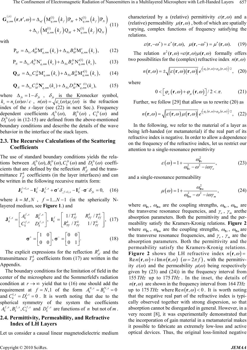 The Confinement of Electromagnetic Radiation of Nanoemitters in a Multilayered Microsphere with Left-Handed Layers 657 11 ,,, ,,MPNP fs qnmnfqf MqnmfN kk Grr (11) 11 1, , MQNQ nm fqnmfM qnmfN kk with , 1, , PM M fs fs MsMqnmsNsMqnms A kB k (12) , 1 1, , PN N fs fs NsNqnmsNsNqnms A kBk (13) 1 1, , MM fs fs MsMqnmsNsMqnms CkBk Q , (14) (1) 1, , () (), fs fs N sM qnm sNsM qnm s CkDk QN N where (15) 1 f sfs , f s is the Kronecker symbol, () /c ss kn , ()()() ss n is the refraction index of the s -lay ndent coefficients er (see fs k A(22) in next Sec.). Frequency depe (), ( fs k B) ,() fs k C and () fs k D in (12-15) are defined from the above-mentioned boundary conditions and theave r in the interface of the stack layers. 2.3. The Recursive Calculations of the Scattering Coefficients describe details o behavio tions f the w The use of standard boundary conditions yields the rela- between ( fs A),(), () fs fs kkk BC and () fs k D coeffi- cients that are defined by the reflection k j f R and the trans- mittance k j f T coend can be written in the following recursive matform: 1, , ,1, 0, sf fsf kkk fskfs JIJ I (16) fficients (in the layer interface ri s) a x f where , (in the spherically N- laye, see nd ,kMN red medium 1... 1fN Figure 1.) a ,, , ,, 1/ / , kkk fs fsFf fs f kk kk , /1/ Ff Ff k k fs fsPf PfPf kk RT T CD k TRT AB JI (17) (18) The explicit expressions for the refle 10 00 , . 00 01 ction k j f R and the transmittance k j f T coefficients from (17) are wri in the A y e microsphere and the Sommerfeld's radiation co tten ppendix. The boundarconditions for the limitation of field in the center of th ndition at r yield that to (16) one should add the requirement at ,1 f N of the form ,, 0 Ns Ns kk AB and 1, 1,ss kk CD. It is worth noting that due to the spherical symmetry of the system th , 0 , e coefficients , ,, f sf kkk s fs A BC and , f s k D are functions of n but not ofm. 2.4. Permittivity, Permeability, and Refractive LH Lrs Index of aye um char permittivity Let us consider a causal linear magnetodielectric medi acterized by a (relative)(, ) r and a (relative) permeability (, ) r, both of which are spatially varying, complex functions of frequency satisfying the relations. (,)(, ),(,)(, ). rrrr (19) The relation 2(, )(, )(, )n rrr s for the (complex) refractiv formally offers two possibilitiee index (,)n r ,/2 ,,, ,ne r rrr (20) ,i r where 0, ,/2 . rr (21) her, we follow [29] that allow us to rewrite (20) as Furt ,,/2 ,,,,ne rrr (22) i rr In the following, we refer to the material of a layer as being left-handed (or metamaterial) if the real part re of its fractive index is negative. In order to allow a dependence on the frequency of the refractive index, let us restrict our attention to a single-resonance permittivity 2 22 1, e ee i P T (23) and a single-resonance permeability 2 22 1 m mm , i P T (24) where e P , m P are the coupling strengths, e T , m T are the trnance frequencies, anansverse resod e , m arethe he absorpti peters. Both the permittivity tper- meability satisfy the Kramers-Kronig relations. Figure 2 where e on aramand P , m P are the coupling strengths, e T , m T are the transverse resonance frequencies, and e , m are the absorption parameters. Both the permittivity and the permeability satisfy the Kramers-Kronig relations. Figure 2 shows the LH refractive index ,n r Re ,Im ,nin rr 2 f , with the permittiv- ity () and the permeability () being res given by (23) and (24)) equency interval from 155 up to 175 THz . In thset, the details of (, )n p ivelyect in the fr e in THz r are shown in the frequency interval from 164 THz up to 175 THz where Re ,0n r. It is worth noting negative real part of the refractive index is typi- cally observed together wi dispersion, so that absorption cannot be disregarded in general. However, in a very recent [8], it was experimentally demonstrated that the incorporation of gain material in a metamaterial makes it possible to fabricate an extremely low-loss and active optical devices. Thus, the original loss-limited negative that the th strong Copyright © 2010 SciRes. JEMAA  The Confinement of Electromagnetic Radiation of Nanoemitters in a Multilayered Microsphere with Left-Handed Layers 658 (a) (b) Figure 2. (Color online.) Real (a) and imaginary (b) parts of the refractive index n 2 f /2fof LH layer in the sta as functions of freck quency , with the permittivity and the permeability being respectively given by (23) and (24) ; Tm THz 0.43 ; 16 10/ 2 P mTm 0.75 ; P eTm em 7 10 Tm (solid lines)]. The val- the parameters have be be similar to those in [29]. Insets show . refractive index can be drasticaimpro with loss compenn the visible wavele en chosen to ails of Re in text. ues of where the det e detailsn and Se Im nin the area Re 0n lly ved sation ingth range. oefficients 3. Numerical Results Analytical solutions to (16) for scattering c ,,, ,, f sfsfs kkk A BCand , f s k D fo spherical stack were derive r cases of or layers in a d in [28]t rresponding 1 . Bu 2 co tr equations are rather laborious, and thus are hardly suitable studythe frequencyspecum for the cases with more than 2layers in the stack already. How- ever, namely in such a structure, one can expect physically interesting phenomena due to the wave re-reflections in the layers of the stack. Similarly to the plane case, such phe- nomena are most pronounced when the thicknesses of the alternating spherical layers are approximately equal to /4 in practice for ing (quarter-wave layers) [11]. In a general case of al- ternating layers (having small losses), the equal- ity 0/ kk kndl , (k d is width, 0/kc ) is considered, t so tha0 / kk dlkn , where l is integer. In this case, the optical thicknesses of the conventional and LH material laye rs are the same112 2 dn dn 3.1. The Spherical Stack We consider a spherical stack with1/ . 00 /2k of the structure equality 0/4 kk dn corresponds to the quarter-wave uity of the field we numeore the details of fre- iation ternating quarter-wave case. (Let us remind that the contins in the layer interfaces requires the continuity of impedances 1/2 /Z which is positive for both the LH and the conventional layers.) Since the amplitude of a spherical electromagnetic wave depends on the distance to the center of thphere, such a 0/4 approximation is only asymptotically close to the plane wave case. So such a structure can be optimized yet with respect to the local properties of the layers in the stack. It is worth to identify the nanosource position in a mi- crosphere. If a nanoemitter is placed close to the center of a microsphere, the system is nearly spherically symmetric; the e micros n, (the refore the modes with small spherical quantum numbers mainly contribute to the sums in (5,10). This case is close to a rotational invariant geometry where the dipole mo- ment orientation does not need to be specified. Therefore, we draw more attention to a case where the nanoemitter is placed rather far from the center in one of the layers of the spherical stack. In such a system, the preferred direction (center-source) arises, therefore larger numbers of spheri- cal modes contribute to DGF (5,10). As a result the fre- quency spectrum of DGF becomes richer but more com- plicated. 3.2. The Numerical Scheme of Applying the Dyadic Green’s Function In this sectiorically expl quency and radial dependencies of nanoemitter rad dyadic Green’s function) for al layers deposited on the surface of a microsphere (Figure 1). We use the following steps: 1) we solve (16) for N-layered spherical structure; 2) we insert the calculated matrices ,,, ,, f sfsfs kkk A BC and , f s k D into (12-15), and fi- nally, 3) to obtain the Green's tensor ,, Grr (4) we calculate the sums in (5) and (10). The realization of such a program requires quite inten- sive computations. Let us outline some detor a nu- merical solution, we represent (16) in ththe ma- tri ails. F e form of x equation ,,, 0 ij Fabcd ,1,2ij with respect to the unknown boundary amplitudes1,, s k aA1, , s k bB ,, N s k cC, N s k dD. Our algorithm has been constructed in such a wayh the re 1, 1,,, ,, , , that witquired coefficients s sNsNs kkk k A BCD and the intermematrices , diate f s (which are necessary for computing the fields in the in- ternal layers) have been calculated. Having these matrices calculated, we further make use them in (4-15). Finally, this allows us to calculate the dyadic Green's tensor in any point of the spherical structure and for any number of layers in the stack. Since the complete Green tensor is known, there is, of course, no obstacle to performing the calculations for an arbitrary position of the nanoemitters in a coated microsphere. We note that such a stack in general k J , where is the reference wavelength. The 0 Copyright © 2010 SciRes. JEMAA  The Confinement of Electromagnetic Radiation of Nanoemitters in a Multilayered Microsphere with Left-Handed Layers 659 may have an arbitrary or even random structure. For our numerical approach, the infinite summation in (5) and (10) has to be truncated. The truncation index max nNmust be chosen, so that a further increase of n does not change the results within a given accuracy. T is w various inaccur he e ph contribute facto to c ysical factor, determining the value of spherical num- bers max nN, is the number of the field eigenmodes that to the spectrum of DGF in the frequency rang of interest. One can see that the contribution of high-order spherical modesnin (5) and (10) may be weakened due to nm C ). Because of the complexity of the field spatial structure, it is difficult to establish some analytical criterion for max N. In the process of our calculations, we have increased the quantity max N till the sum in (4) ceases hange essentially. Usually max N did not exceed max 25 30N. We have found that such an approxima- tion remains king well up to very high spherical numbers (WGM regime). It orth noting that the con- tinuity of DGF in the layer interfaces is very sensitive to acies in calculations and can thus serve as a good criterion for estimating the global accuracy of the results. Since nanoemitters (e.g. nanorods) are highly polarized objects, we pay more attention to the case where the dipole orientation of the nanoemitter is ˆ d=d r (6 wor , so only the tan- gential components of the Green's tensor G contribute. en us 3.3. The Parameters of Calculations The following parameters have beed in our calcula- tions: the geometry of a system is .., A BCBBDwhereCBC the letters ,,, A BCD indicate the materials 1.75 m in the system, 0 2/ ,171.5 000 K fcf THz . A bottom microsphere has a refraction index 4 41.52 10ni ( A , glass, radius 1000 nm). The refof the LH layer is (22) (see Figure 2 for details) (B, 2 width 300 nm) and 11n (D, surrounding the realistic layers case we added to each i n a small imaginary part, which corresponds to the material dissipa- tion. Wat e such a open s), there are losses due to leakage of the field into the surrounding space. 3.4. The Frequency Spectrum of the GF The above-written approach has allowed us to explore both the frequency spectrum and the raction index 3 10 (2,SiO ,C space). To co given by 7nm ), width 43 1.46 3ni nsider e note thven in a material lossless case in system (ystem radial distribution of the here. The 3-7 com po Green’s function in the multilayered microsp results of our calculations are shown in Figures Mainly, we study the case of 7-layered systems (spherical stack with 7 layers deposited on the surface of the microsphere). In Figure 3(a), we plot the frequency dependence of the imaginary part for the tangential nent of GF ,,Grrf in the source point rr , (a) (b) Figure 3. (Color online.) Frequency spectrum of the imagi- nary part of the GF (arbitrary units) in the area of Im, ,WGrrf 0Re n (see Figure 2(a)), (a) 7 multilays; (b) 5 multila itter is located at r compari ectrum of the er yers. where the nanoem1480rnm in 2 SiO layer. Foson, we also present in Figure 3(b) the frequency sp Im G ure for a 5-layer of the spectrumstack. One can see that the struct is W similar in both cases. e observe from Figure 3 (a) that the spectrum of Im( ) G consists of peaks with amplitudes; the highest peaks are located at 164THz and 168THz . They- have a rather indented various formhtion of due to te contribu se cal modes veral close resonances corresponding to various spheri- . Such peaks have a typical Lorentzian line shape 22 Im /G , where is a detrom the resonance and uning f is the linewidth. 3.5. The Radial Structure of GF in Spherical Stack Some interesting special cases can be considered by ana- lyzing ,Im ,,WrfGrrconstf as a func of r fferent tion for a di f . In Figure 4, the radial distribu- tions corresponding to th 0nm ,Wrfe frequency reso- nances at 164 THz , 165 THz, and 168 THz (solid lines, 148r is the position of a nanoem en are shown ffers considerably onance he va itter), and the refrctive index depdencies of the radial stack (dash lines) . We observe from Figure 4 that the field structure difor res correspond- lues of the dispersive refractive index of the LH layers Re ()nf . Figure 4(a) shows that for 164 a ing to t s f THz the field has the form of a resonant oscilla- tion in the LH layer. For 168 f THz (see Figure 4(c)), the field has shape of a single spatial pulse located in the Copyright © 2010 SciRes. JEMAA  The Confinement of Electromagnetic Radiation of Nanoemitters in a Multilayered Microsphere with Left-Handed Layers 660 area of the inte th first LH layer with a 2 SiO layer. 165 rface ofe The case f THz Figure 4(b)) is an intermediate case. We observe that in all shown cases, the field is con- fined by an LH layer and practically does not leave the spherical stack. It is well due to the fluctuation-dissipation theorem the correlation function of the photon states in the absorbing environment for temperature T can be written down with the he known that lp of the macroscopic GF as fows [30] llo 2 2coth() Im,,. 2 rr rr T c EE G (25) In particular, from (25) one can see that the case rr yields the inequalitthat correspo the energy ofgnetic field y Im ,0rr G a fluctuating electroma nds to r at E small dissipation [30]: r 2Im ,GErr , where (a) (b) (c) Figure 4. (Color online.) Details of radial depe of the imaginary part of the GF V (abi- trary units) in the area ofon frequencies (a) ndence ,rrf Im ,WG 0n, (see Figure 2 (a))r , Re 164 , f THz 165, f THz (b), and (c) 168 f THz (solid line). Radius r is normalized on the radius of the internal microsrce is placed at 1 /1.48rr (smw shows location of nanoemitters) in. Distribution he stack is shown by a dashed line; the stack consists of 7 layers. Internal microsphere (glass) occupies the area 1 /rris L H M w i t h Re 0n, t hen l a yer 2 SiO with Re 0n, etc. It i s visi ble that for case (a), there finement of the electromagnetic field already in the first LHM layer. The spatial variation of W becomes less with ose of the emitter (field) fsee case(b). ase (cgle field pulse with large amplitude is localized in the first LHM layer. The amplitude of the field decreases appreciably at the increase the rad r. phere 1 r. The n all arro layer of the stack requency ius anosou , the secon , 1- s t l aye r y a sin d Re nalong t is a con n increa For c) on 1 l ,Grr is the GF, which is (,)G rr in our case. There- fore, the field structure shown in Figure 4(a,b,c) may be treated as a strong correlation of the electromagnetic fields in the vicinity of the LH layer with Re 0nf. Figure 5 shows that the field structun in Figure 4 for 1480rnm re (show ) does not change considerably at the shift of the nanoemitter along the layer to 1700rnm . The natural question arises, how much cack confine the field energy for a stack with various numbers of layers? 3.6. GF for Various Numbers of Layers in the Stack In Figure 6, the structure Im, ,WGrrf for a n such a sta numbers, the spectral peak practically does not considered stack (LH ayered er the system with various layers is shown at frequency168THz . From Figure 6, we observe that with a change in the er of lay variate. This means that for a layers and conventional layers), the field beyond the first LH layer is so small that the wave boundary re-reflections do not affect the structure of the field in the LH layer. This allows us to conclude that the structure of the spectrum is defined mainly by the intrinsic properties of the spherical stack and weakly depends of the nanoemitter location. 3.7. The Structure of the GF in a LH Layer Furthermore, in some experiments it is important to iden- tify the spatial distribution of the field (for some reso- nances) radiated by nanosources located in a multil microsphere. Therefore, it is of interest to consid spatial field distribution in a cross-section (,,rconst ) (a) (b) (c) Figure 5. (Color online.) The same as in Figure 4 but for position of a nanoemitter farther from the center at 0 1 /1.7rr . We observe that for such a location of nano- trength source, the s ImWG is less than for case 8 1 /1.4rr shown in Figure 4. Copyright © 2010 SciRes. JEMAA  The Confinement of Electromagnetic Radiation of Nanoemitters in a Multilayered Microsphere with Left-Handed Layers 661 that contains both the center of the coated microsphere and the nanoemitter. Taking into account the physical meaning is of interest to calculate the DGF spectrum fortwo nanoemitters placed at points r and r in a multi- osphere for a resona of (25), it coated micrnt frncy Figure 7, eque. In such a distribution is shown for168 f THz (see Figur e 4(c)). From (25), one can see that Im, ,Grrf is propor- Figure 6. (Color online.) Radial dependencies of imaginary part of the GF (arbitrary units), in area of , at frequency Im, ,WGrrf 0n (see Figure 2(a))Re 168 f THz A small stack. for d if f e re n t n u m be r s of l a shift was added to every n in the stack. yers in th e sp h e ri ca l line to separate the corresponding close curves. The dashed line shows the radial dependencies of Figure 7. (Color online.) Spatial structure W (arbitrary units), ) ,Im(,,WrG rr 4000rnmand 02 in a cross-section 0 /4 of a coated microsphere with stack for eigenfrequency 168 f THz rnm . The othe o . A r pa- ent of the field in the area of stack. See details to thetromagnetic f r, while nanoemitter is placed at point 1480 rameters are the same as in Figure 4. One canbserve the confinem the LH layer of the in text. tional energy of the fluctuating elecield in the position of a nanoemitte , ,Grrf corresponds to the correlations of the photonic states at r and r Im . We observe from Figure 7 that the spatial distri- bution Im, ,Grrf has well-defined peaks not only at rr , but also at angles i along the circle where rr . This means that a strong correlat produced by two separated nanoemitters can be arisen at such resonance. It is worth to note that such a field state is not a pheral but a state of the macroscopic me dressed by the electromgnetic field [30]. We also e from Figure 7 that the field structure inside of a alternating stack is anisotropic and quite intricate, but the field amplitudes beyond the coated microsphere are small. Nevertheless, a spectral detector placed outside the micro- sphere still enables a noncontact monitoring of the proper- ties of a nanoemitter located inside a multicoated micro- sphere. 3.8. Discussion We observe that the use of the of GF technique allows a clear description and a self-consistent understanding of the physics ion of field states a otonic state in gen dium, a observ of the electromagnetic phenomena in the spherical rs included with respect of the standard the spherical modes of the system. We stack with LH laye decompositions on have shown that the difference in the location of a nano- source may lead to the essentially distinct wave pictures. As a result the frequency spectrum of radiations becomes rather indented as it is defined by the sum of the various spherical harmonics with the frequency depending field amplitudes. Such a spectrum differs sufficiently from the case of a spherical stack with conventional materials. Therefore the behavior of the considered compound sys- tem is instructively to compare with a limit infinite plane alternating case that has an analytical solution. The latter stack consists of two different materials with widths i a and impedances 1/2 / ii , 1, 2i , where both i and i are dispersiveless quantities. The first layer is a conventional dielectric, while the second layer may be LH material with 0 and 0 . The dispersion relation with 2 f versus the Bloch parameter for a 1Dcase can be written as (see e.g. [25]) coscos cossin sin,ppqp p (26) with 21 1/2//1,q 1,2 11 /,pnac 22 1 /,na na1, 1 where 1 for the LH ma and nre the refractive indices. The equati terial, (26) is i a d for on solve to determine the forbi negative sign of the refractive index s of parameter dden bands. He is shown explicitly re the (by mean ), so in (26) bo are all positive th refractive indices 1, 2. For quarter-wave stack 1n and 1 (conventional layer) (26) is reduced to the following Copyright © 2010 SciRes. JEMAA  The Confinement of Electromagnetic Radiation of Nanoemitters in a Multilayered Microsphere with Left-Handed Layers 662 22 coscossin ,pq p where 0 /2pff ,00 1/ is the reference frequency he alternating stack) that has well-known son to e the properties of the band gaps for a conventional f of tlutio defin /4 dielectric plan ver, for 1 e stack, see e.g. Cha. 6 in [31]. p Howe (LH layer) in contrast to 1 case, ation the equ 22 coscossin ,pqp (27) real solution for has a only for pl or 0 2 l f flf (1,2, ...l) in dently of material imped (pa- rameter q). Teans that in (27) the transm bands shrink to depen his m zero [This co odic sphewhextr ances ittance changed for a e owever, for 25]. rical stack, re nclusion is re the e d [26 quasiperi sidered mely narrow transmittance peaks a generate]. H con here dispersive (with losses) LH case the ref- erence stack frequency 0171.5 f THz such an area l f with high transmittance is far from the working frequency range of 175 f TGz, where Re n is negative, see Fig- ure 2. Thus, considered here the frequency range corre- sponds to a forbidden gap of the infinite plane stack with LH layers included, so t e nt of the electro- magnetic field by the LH layer can be expected. Further- more, the e used hes not only to iden- tify the layers in which such a confinement occurs, but yet to explore the spatial structure of the field in such an area, see Figure 4 and Figure 7. 4. Conclusions We have studied the frequency spectrum and spatial de- pendences of the electromagnetic field (the dyadic Green's function), radiated by a na hconfineme GF techniqure allow noemitters (considered in a ed into the multilayered microsphe tive quarter-wave spherical stack with RENCES trodynamics of Substances with es of ε and μ,” Sovi et Ph ysi cs D. Schurig and D. R. Smith, “Controllin Elctromagnetic Fields,” Science, Vol. 312, No. 5781, 2006, pp. 1780-1782 -Free 2, 2005, pp. 352-418. dipole model) plac coated by the alterna re [1 LH layers included. We found that in the frequency range where LH layers have negative refraction index the fre- quency spectrum of the field consists of the series of nar- row and well separated peaks. In the area of such reso- nances the LH layers can confine the field of nanoemitters; as a result, the photon states become located in the coated microsphere and practically do not leak into a surrounding space. As the width of resonant peaks is rather small, it allows creating highly polarized nanoemitters oscillating with high Q factor to actively control the polarization state of microcavity photons. Such states can be useful not only for the operational purposes, but also for quantum information technologies. 5. Acknowledgements The work of G.B. is partially supported by CONACYT grant No. 25564. REFE [1] V. G. Veselago, “The Elec Simultaneously Negative Valu Uspekhi, Vol. 10, No. 509, 1968, pp. 509-514. [2] J. B. Pendry, . [3] C. M. Soukoulis, S. Linden and M. Wegener, “Negative Refractive Index at Optical Wavelengths,” Science, Vol. 315, No. 5808, 2007, pp. 47-49. [4] J. Valentine, et al., “Three-Dimensional Optical Metama- terial with a Negative Refractive Index,” Nature, Vol. 455, No. 7211, 2008, pp. 376-379. [5] S. Zhang, et al., “Experimental Demostration of Near- Infrared Negative-Index Metamaterial,” Physical Review Letters, Vol. 95, No. 13, 2005, pp. 137404-137408. [6] V. M. Shalaev, “Optical Negative-Index Material,” Nature Photonics, Vol. 1, 2006, pp. 41-48. [7] K. L. Tsakmakidis, A. D. Boardman and O. Hess, “Trapped Rainbow Storage of Light in Metamaterials,” Nature, Vol. 450, No. 7168, 2007, pp. 397-401. [8] S. Xiao, V. P. Drachev, A. V. Kildishev, et.al., “Loss and Active Optical Negative-Index Metamaterial,” Nature, Vol. 466, No. 7307, 2010, pp. 735-738. [9] V. B. Braginsky, M. L. Gorodetsky and V. S. Ilchenko, “Quality-Factor and Nonlinear Properties of Optical Whispering-Gallery Modes,” Physics Letters A, Vol. 137, 1989, No. 7-8, pp. 393-397. [10] J. A. Stratton, “Electromagnetic Theory,” McGraw-Hill, New York, 1941. [11] K. G. Sullivan and D. G. Hall, “Radiation in Spherically Symmetric Structures. I. The Couple-Amplitude Equations for Vevtor Spherical Waves,” Physics Review A, Vol. 50, 1994, p. 2701 2] G. Burlak. “The Classical and Quantum Dynamics of the Multispherical Nanostructures,” Imperial College Press, London, 2004. [13] C. T. Chan, W. Y. Zhang, Z. L. Wang et.al. “Photonic Band Gaps from Metallo-Dielectric Spheres,” Physica B., Vol. 279, No. 1-3, 2000, pp. 150-154. [14] H. Miyazaki, H. Miyazaki, K. Ohtaka, et.al., “Photonic Band in Two-Dimensional Lattices of Micrometer-Sized Spheres Mechanically Arranged under a Scanning Electron Microscope,” Journal of Applied Physics, Vol. 87, No. 10, 2000, pp. 7152-7158. [15] N. Le Thomas, U. Woggon, O. Schops, M. V. Artemyev, M. Kazes and U. Banin, “Cavity QED with Semiconductor Nanocrystal,” Nano Letters, Vol. 6, No. 3, 2006, pp. 557- 561. [16] A. Moroz, “A Recursive Transfer-Matrix Solution for Adipole Radiating Inside and Outside a Stratified Sphere,” Annals of Physics, Vol. 315, No. [17] P. Voarino, C. Deumie and C. Amra, “Optical Properties Calculated for Multidielectric Quarter-Wave Coatings on Microspheres,” Optics Express, Vol. 12, No. 19, 2004, p. Copyright © 2010 SciRes. JEMAA  The Confinement of Electromagnetic Radiation of Nanoemitters in a Multilayered Microsphere with Left-Handed Layers Copyright © 2010 SciRes. JEMAA 663 . 3, 2004, pp. 793-805. s etters, Vol. 94, No. 1, 2005 -068105. 1-1968. n Journal of Chemistry, Vol. view E, Vol. 66, No. 3, 2002, eriodic Left-Handed Stack,” Optics Transactions on Microwave Media,” Physical Review A, Vol. 68, No. 4, cal Waves in Crystalls,” Willey- ansmittance in the spherical layer interfaces without sentation. In this Appendix such a represen- 4476. [18] C.-C. Chen, Y.-L. Tsai, C.-L. Hsu, et.al., “Propagation Loss Reduction of Photonic Crystal Slab Waveguides by Micros- pheres,” Optics Express, Vol. 12, No. 17, 2004, p. 3934. [19] H. T. Miyazaki, H. Miyazaki, Y. Jimba, et.al., “Light Diffraction from a Bilayer Lattice of Mocrospheres Enhaced by Specular Resonance,” Journal of Applied Physics, Vol. 95, No [20] Y. Z. Long, Z. J. Chen, Y. J. Ma et.al., “Electrical Conductivity of Hollow Polyaniline Microspheres Synthe- sized by a Sel-Assembly Method,” Applied Physics Letter, Co Vol. 84, No. 12, 2004, p. 2205. [21] N. Le Thomas, E. Herz, O. Schops, U. Woggon and M. V. Artemyev, “Exciton Fine Structure in Single CdSe Nanorods,” Physical Review L, “E pp. 016803-016807. [22] M. Manghi , X. Schlagberger and R. R. Netz, “Propulsion with a Rotating Elastic Nanorod,” Physical Review Letters, Vol. 96, No. 6, 2006, pp. 068101 [23] A. Petukhova, A. S. Paton, Z. Wei, et.al., “Polymer Multilayer Microspheres Loaded with Semiconductor Quantum Dots,” Advanced Functional Materies, Vol. 18, No. 13, 2008, pp. 196 [24] A. Petukhova, A. S. Paton, I. Gourevich, et.al., “Hybrid Microspheres with Alternating Layers of Apolimer and Metal Nanoparticles,” Canadia Appendix n the above was used the coefficients reflection and 88, No. 3, 2010, pp. 298-304. [25] I. S. Nefedov and S. A. Tretyakov, “Photonic Band Gap Struture Containg Metamaterial with Negative Permittivity and Permeability,” Physical Re pp. 036611-036616. [26] G. Burlak, A. Diaz-de-Anda, R. S. Salgado and J. P. Ortega, “Narrow Transmittance Peaks in a Multilayered Micro- sphere with a Quasip mmunications, Vol. 283, No. 19, 2010, pp. 3569-3577. [27] J. D. Jackson. “Classical Electrodynamics,” John Willey and Sons, New York, 1975. [28] L.-W. Li, P.-S. Kooi, M.-S. Leong and T.-S. Yeo, lectromagnetig Dyadic Green’s Function in Spherically Multilayered Media,” IEEE Theory and Techniques, Vol. 42, No. 12, 1994, pp. 2302-2310. [29] H. T. Dung, S. Y. Buhmann, L. Knoll, et. al., “Electro- magnetic-Field Quantization and Spontaneous Decay in Left-Handed 2003, pp. 043816-043831. [30] L. D. Landau and E. M. Lifschitz. “Statistical Physics, Part 2,” Pergamon Press, Oxford, England, 1981. [31] A. Yariv and R. Yeh, “Opti Interscience, New York, 2002. 111 11 111 , fff ffff ff N Pf fff fff ff ff kJ HJH TkJH kJH (34) I tr 111 11 111 , fff ffff ff N Ff ffffff ffff kJ HJH TkJ HkJ H detailed repre tation for coefficients reflection if R and transmittance if T (,kMN,,iPF) throw the spherical stack is written as [28], k k (35) with 111 11 , fffff 1 f f fff M ff fff ff ff kHH kH RH kJH (28) Pf f H kJ , ilni l J jkR (36) 1, ilnil H hkR (37) 111 111 , ffffff ff ff M Ff f ff fff ff ff kJJ kJJ RkJ HkJ H 1|, il n ilk R dj Jd (29) (38) 111 111 , ffffff f fff M Pf fff fff ff ff kHH kHH RkJH kJH (30) 1 1| il n ilk R dh Hd 111 111 , ffffff ffff N Ff f ff fff ff ff kJJ kJJ RkJ HkJ H (31) 111 11 111 , and stand for s Hank ectively, -thterial, while is th om) wserve th g (39) Here () n jx el functio ma (28-35 hbors () n hx ns resp l R e ob pherical Bessel and is the wave vector in the i k e rad at i Fr nei ius of the i-th layer. if the parameters of , (32) fff ffff ff M Pf fff fff ffff kJ HJ H TkJH kJH f and )(1f layers are cl 111 11 111 , fff ffff ff M Ff ffffff ffff kJ HJ H TkJ HkJ H ose then te reflec- on of h ti such ,(ff1) 0 k if interface is smallR (33) |