Paper Menu >>
Journal Menu >>
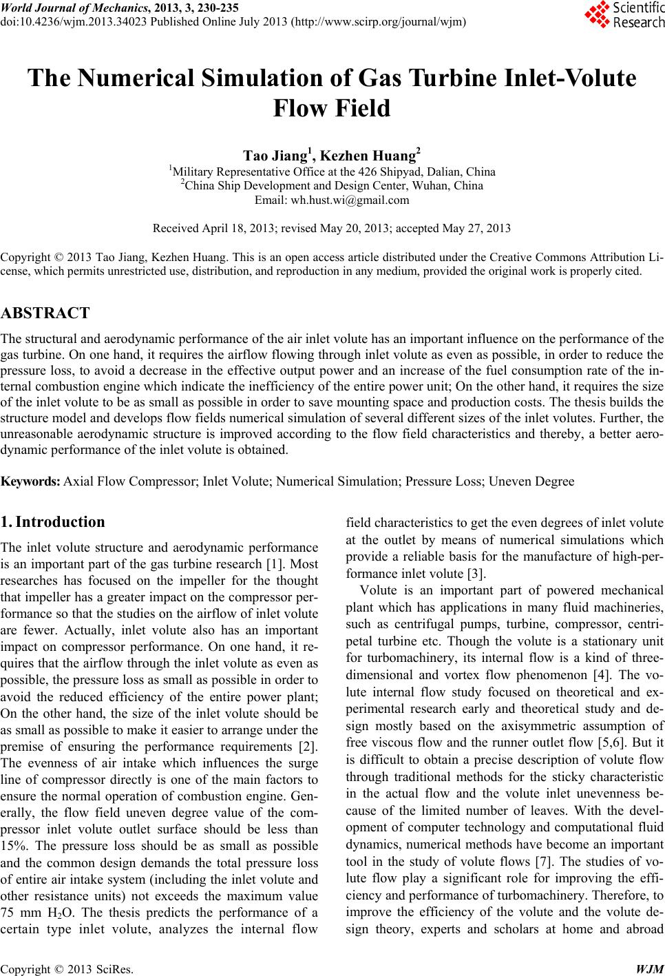 World Journal of Mechanics, 2013, 3, 230-235 doi:10.4236/wjm.2013.34023 Published Online July 2013 (http://www.scirp.org/journal/wjm) The Numerical Simulation of Gas Turbine Inlet-Volute Flow Field Tao Jiang1, Kezhen Huang2 1Military Representative Office at the 426 Shipyad, Dalian, China 2China Ship Development and Design Center, Wuhan, China Email: wh.hust.wi@gmail.com Received April 18, 2013; revised May 20, 2013; accepted May 27, 2013 Copyright © 2013 Tao Jiang, Kezhen Huang. This is an open access article distributed under the Creative Commons Attribution Li- cense, which permits unrestricted use, distribution, and reproduction in any medium, provided the original work is properly cited. ABSTRACT The structural and aerodynamic performance of the air inlet volute has an important influence on the performance of the gas turbine. On one hand, it requires the airflow flowing through inlet volute as even as possible, in order to reduce the pressure loss, to avoid a decrease in the effective output power and an increase of the fuel consumption rate of the in- ternal combustion engin e which indicate the inefficiency of the en tire power unit; On the other hand, it requires the size of the inlet volute to be as small as possible in order to save mounting space and production costs. The thesis builds the structure model and develops flow fields numerical simulation of several different sizes of the inlet volutes. Further, the unreasonable aerodynamic structure is improved according to the flow field characteristics and thereby, a better aero- dynamic performance of the inlet volute is obtained. Keywords: Axial Flow Compressor; Inlet Volute; Numerical Simulation; Pressure Loss; Uneven Degree 1. Introduction The inlet volute structure and aerodynamic performance is an important part of the gas turbine research [1]. Most researches has focused on the impeller for the thought that impeller has a greater impact on the compressor per- formance so that the studies on the airflow of inlet volute are fewer. Actually, inlet volute also has an important impact on compressor performance. On one hand, it re- quires that the airflow thr ough the inlet volute as even as possible, the pressure loss as small as possible in order to avoid the reduced efficiency of the entire power plant; On the other hand, the size of the inlet volute should be as small as possible to make it easier to arrange under the premise of ensuring the performance requirements [2]. The evenness of air intake which influences the surge line of compressor directly is one of the main factors to ensure the normal operation of combustion engine. Gen- erally, the flow field uneven degree value of the com- pressor inlet volute outlet surface should be less than 15%. The pressure loss should be as small as possible and the common design demands the total pressure loss of entire air intake system (including the inlet volute and other resistance units) not exceeds the maximum value 75 mm H2O. The thesis predicts the performance of a certain type inlet volute, analyzes the internal flow field characteristics to get the even degrees of inlet volute at the outlet by means of numerical simulations which provide a reliable basis for the manufacture of high-per- formance inlet volute [3]. Volute is an important part of powered mechanical plant which has applications in many fluid machineries, such as centrifugal pumps, turbine, compressor, centri- petal turbine etc. Though the volute is a stationary unit for turbomachinery, its internal flow is a kind of three- dimensional and vortex flow phenomenon [4]. The vo- lute internal flow study focused on theoretical and ex- perimental research early and theoretical study and de- sign mostly based on the axisymmetric assumption of free viscous flow and the runner outlet flow [5,6]. But it is difficult to obtain a precise description of volute flow through traditional methods for the sticky characteristic in the actual flow and the volute inlet unevenness be- cause of the limited number of leaves. With the devel- opment of computer technology and computational fluid dynamics, numerical methods have become an important tool in the study of volute flows [7]. The studies of vo- lute flow play a significant role for improving the effi- ciency and performance of turbomachinery. Therefore, to improve the efficiency of the volute and the volute de- sign theory, experts and scholars at home and abroad Copyright © 2013 SciRes. WJM 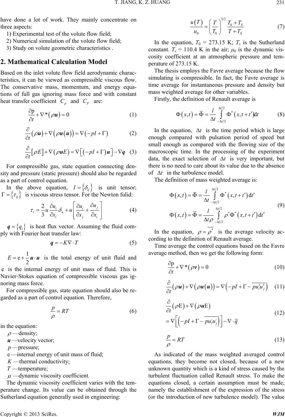 T. JIANG, K. Z. HUANG 231 have done a lot of work. They mainly concentrate on three aspects: 1) Experimental test of the volute flow field; 2) Numerical simulation of the volute flow field; 3) Study on volute geometric characteristics . 2. Mathematical Calculation Model Based on the inlet volute flow field aerodynamic charac- teristics, it can be viewed as compressible viscous flow. The conservative mass, momentum, and energy equa- tions of full gas ignoring mass force and with constant heat transfer coefficient p C and F C are: p* t u0 (1) pI t uuu (2) EE pI t uuq (3) For compressible gas, state equation connecting den- sity and pressure (static pressure) should also be regarded as a part of control equation. In the above equation, ij I is unit tensor; ij is viscous stress tensor. For the Newton fulid: 2 3 j ii in ij u uu uu i x xx (4) i qq is heat flux vector. Assuming the fluid com- ply with Fourier heat transfer law: K T q (5) 1 e2 E uu is the total energy of unit fluid and e is the internal energy of unit mass of fluid. This is Navier-Stokes equation of compressible viscous gas ig- noring mass force. For compressible gas, state equation should also be re- garded as a part of control equation. Therefore, pRT (6) in the equation: —density; u—velocity vector; p—pressure; e—internal energy of unit mass of fluid; K—thermal conductivity; T—temperature; —dynamic viscosity coefficient. The dynamic viscosity coefficient varies with the tem- perature change. Its value can be obtained through the Sutherland equation generally used in engineering: 32 0 00 S S uT TT T uTTT (7) In the equation, T0 = 273.15 K; Ts is the Sutherland constant. Ts = 110.4 K in the air; μ0 is the dynamic vis- cosity coefficient at an atmospheric pressure and tem- perature of 273.15 K. The thesis employs the Favre average because the flow simulating is compressible. In fact, the Favre average is time average for instantaneous pressure and density but mass weighted average for other variables. Firstly, the definition of Renault average is 2* 2 ,, t t ld x tx t ttt (8) In the equation, t is the time period which is large enough compared with pulsation period of speed but small enough as compared with the flowing size of the macroscopic time. In the processing of the experiment data, the exact selection of is very important, but there is no need to care about its va lue du e to the ab sence of t t in the turbulence model. The definition of mass weighted average is: 2* 2 2** 2 ,, ,, t t t t l xtxt tt t l d d x tx t ttt (9) In the equation, * is the average velocity ac- cording to the definition of Renault average. Time average the control equations based on the Favre average method, then we get the following form: p* t 0 v (10) ij pIpu u t uuu (11) j EE i t pIpu uq ,, u (12) pRT (13) As indicated of the mass weighted averaged control equations, they become not closed, because of a new unknown quantity wh ich is a kind of stress caused by the turbulent fluctuation called Renault stress. To make the equations closed, a certain assumption must be made, namely the establishment of the expression of the stress (or the introduction of new turbulence model). The value Copyright © 2013 SciRes. WJM  T. JIANG, K. Z. HUANG 232 of turbulent fluctuation and the average time can be linked through these expressions or turbulence model equations. There is no specific laws of physics can be used to create turbulence model, therefore, the current turbulence model can only be based on experimental ob- servations. According to Boussinesq and theoretical assumptions of molecular motion: 2 3 j ii ijiij iij jji u uu uu uu xxx 2 3 (14) In the equation, i different to u is the eddy vis- cosity coefficient which is a function of the spatial coor- dinates, depending on the flow state rather than a physi- u cal parameter. 222 1 2ijk kuuu is the fuctuating kinetic energy of unit mass fluid turbulence. Now, define 222 1 33 tijk puuu 2 k and sub- stitute (2.14) into the control equations: p* t u0 (15) eff p t uuu (16) eff EE t pI uq u (17) pRT (18) In the equations, is a combined effective pres- sure of and . eff p pt p 2 3 eff t ppp k (19) Further , f or the ij 2 3 j ki iji iji kj u uu uu uu i x xx (20) Thereby, if the effective viscosity coefficient , substitute it into the above equation, we get: eff t uuu 2 3 j ki ijeffij eff kj u uu uu i x xx (21) So, the control equations of (15)-(18) are identical to the formulas of (1)-(3), (6). 3. Numerical Modeling and Simulation Two volute models are designed according to the turbine shape and the inlet volute whose intake port is designed in a circular shape is named Type A. The geometric model in Figure 1. Due to the irregularity of the model structure, it is dif- ficult to generate the overall structure of the mesh. So it is necessary to do the segmentation processing, then the regular structures generate the structural mesh and the irregular structures generate non-structural mesh. Note that we must act from input to output, output to input or from the middle to both sides to generate the mesh. The mesh number is between 20 to 30 million. The results are shown in Figure 2. According to the model characteristics and perform- ance requirements of an ideal gas as working fluid, the given boundary conditions are as follows: Input: mass flow inlet, the total temperature of 300 K; Output: pressure on exports, the total temperature of 300 K, to adjust the inlet mass flow rate so that the exit velocity can reach 100 m/s; Solid wall: adiabatic, no-slip. Make the numerical simulation of volute flow field according to the control equations of the Favre averaged Figure 1. Type A turbin volute. Figure 2. Type A model mesh. Copyright © 2013 SciRes. WJM 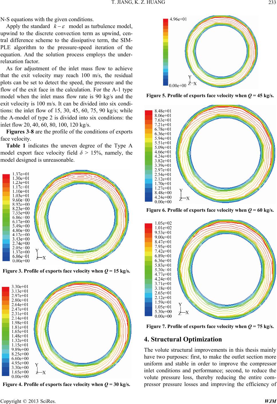 T. JIANG, K. Z. HUANG 233 N-S equations with the given conditions. Apply the standard k model as turbulence model, upwind to the discrete convection term as upwind, cen- tral difference scheme to the dissipative term, the SIM- PLE algorithm to the pressure-speed iteration of the equation. And the solution process employs the under- relaxation factor. As for adjustment of the inlet mass flow to achieve that the exit velocity may reach 100 m/s, the residual plots can be set to detect the speed, the pressure and the flow of the exit face in the calculation. For the A-1 type model when the inlet mass flow rate is 90 kg/s and the exit velocity is 100 m/s. It can be divided into six condi- tions: the inlet flow of 15, 30, 45, 60, 75, 90 kg/s; while the A-model of type 2 is divided into six conditions: the inlet flow 20, 40, 60, 80, 100, 120 kg/s. Figures 3-8 are the profile of the conditions of exports face velocity. Table 1 indicates the uneven degree of the Type A model export face velocity field δ > 15%, namely, the model designed is unreasonable. Figure 3. Profile of exports face velocity when Q = 15 kg/s. Figure 4. Profile of exports face velocity when Q = 30 kg/s. Figure 5. Profile of exports face velocity when Q = 45 kg/s. Figure 6. Profile of exports face velocity when Q = 60 kg/s. Figure 7. Profile of exports face velocity when Q = 75 kg/s. 4. Structural Optimization The volute structural improvements in this thesis mainly have two purposes: first, to make the outlet section more uniform and stable in order to improve the compressor inlet conditions and performance; second, to reduce the volute pressure loss, thereby reducing the entire com- pressor pressure losses and improving the efficiency of Copyright © 2013 SciRes. WJM 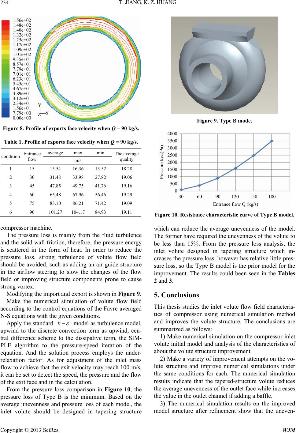 T. JIANG, K. Z. HUANG 234 Figure 8. Profile of exports face velocity when Q = 90 kg/s. Table 1. Profile of exports face velocity when Q = 90 kg/s. average max min condition Entrance flow m/s The average quality 1 15 15.54 16.36 13.52 18.28 2 30 31.48 33.98 27.82 19.06 3 45 47.85 49.75 41.76 19.16 4 60 65.48 67.96 56.46 19.29 5 75 83.10 86.21 71.42 19.09 6 90 101.27 104.17 84.93 19.11 compressor machine. The pressure loss is mainly from the fluid turbulence and the solid wall friction, therefore, the pressure energy is scattered in the form of heat. In order to reduce the pressure loss, strong turbulence of volute flow field should be avoided, such as adding an air guide structure in the airflow steering to slow the changes of the flow field or improving structure components prone to cause strong vortex. Modifying the import and export is shown in Figure 9. Make the numerical simulation of volute flow field according to the control equations of the Favre averaged N-S equations with the given conditions. Apply the standard k model as turbulence model, upwind to the discrete convection term as upwind, cen- tral difference scheme to the dissipative term, the SIM- PLE algorithm to the pressure-speed iteration of the equation. And the solution process employs the under- relaxation factor. As for adjustment of the inlet mass flow to achieve that the exit velocity may reach 100 m/s, it can be set to detect the speed, the pressure and the flow of the exit face and in the calculation. From the pressure loss comparison in Figure 10, the pressure loss of Type B is the minimum. Based on the average unevenness and pressure loss of each model, the inlet volute should be designed in tapering structure Figure 9. Type B mode. Figure 10. Resistance characteristic curve of Type B model. which can reduce the average unevenness of the model. The former have required the unevenness of the volute to be less than 15%. From the pressure loss analysis, the inlet volute designed in tapering structure which in- creases the pressure loss, however has relative little pres- sure loss, so the Type B model is the prior model for the improvement. The results could been seen in the Tables 2 and 3. 5. Conclusions This thesis studies the inlet volute flow field characteris- tics of compressor using numerical simulation method and improves the volute structure. The conclusions are summarized as follows: 1) Make numerical simulation on the compressor inlet volute initial model and analysis of the characteristics of about the volute structure improvement. 2) Make a variety of improvement attempts on the vo- lute structure and improve numerical simulations under the same conditions for each. The numerical simulation results indicate that the tapered-structure volute reduces the average unevenness of the outlet face while increases the value in the outlet channel if adding a baffle. 3) The numerical simulation results on the improved model structure after refinement show that the uneven- Copyright © 2013 SciRes. WJM 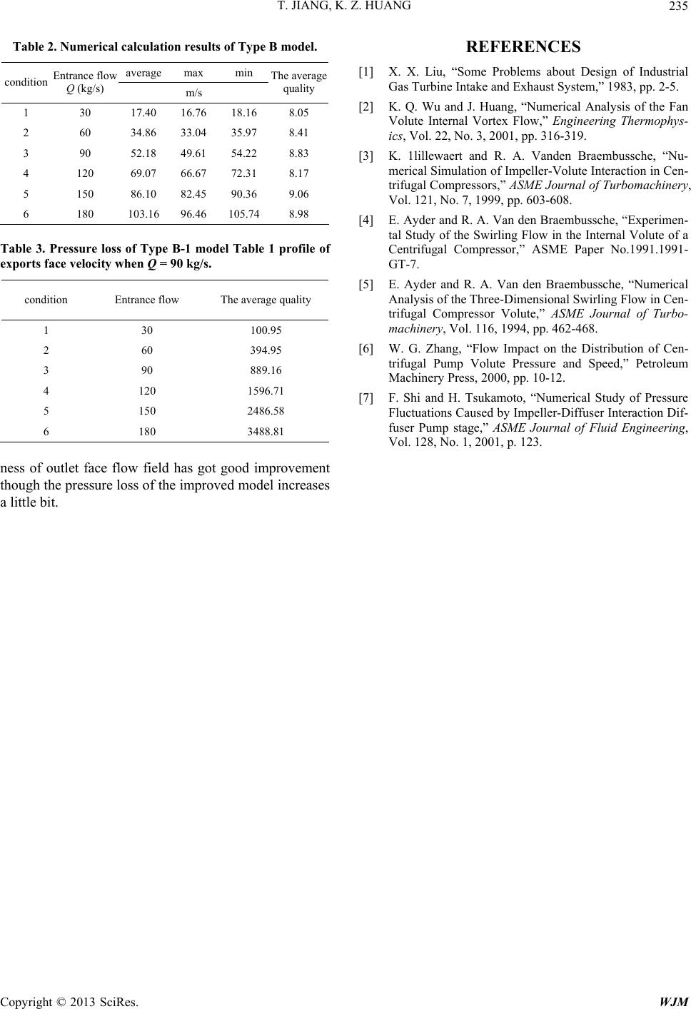 T. JIANG, K. Z. HUANG Copyright © 2013 SciRes. WJM 235 Table 2. Numerical calculation results of Type B model. average max min condition Entrance flow Q (kg/s) m/s The average quality 1 30 17.40 16.76 18.16 8.05 2 60 34.86 33.04 35.97 8.41 3 90 52.18 49.61 54.22 8.83 4 120 69.07 66.67 72.31 8.17 5 150 86.10 82.45 90.36 9.06 6 180 103.16 96.46 105.74 8.98 Table 3. Pressure loss of Type B-1 model Table 1 profile of exports face velocity when Q = 90 kg/s. condition Entrance flow The average quality 1 30 100.95 2 60 394.95 3 90 889.16 4 120 1596.71 5 150 2486.58 6 180 3488.81 ness of outlet face flow field has got good improvement though the pr essure loss of the improved model increases a little bit. REFERENCES [1] X. X. Liu, “Some Problems about Design of Industrial Gas Turbine Intake and Exhaust System,” 1983, pp. 2-5. [2] K. Q. Wu and J. Huang, “Numerical Analysis of the Fan Volute Internal Vortex Flow,” Engineering Thermophys- ics, Vol. 22, No. 3, 2001, pp. 316-319. [3] K. 1lillewaert and R. A. Vanden Braembussche, “Nu- merical Simulation of Impeller-Volute Interaction in Cen- trifugal Compressors,” ASME Journal of Turbomachinery, Vol. 121, No. 7, 1999, pp. 603-608. [4] E. Ayder and R. A. Van den Braembussche, “Experimen- tal Study of the Swirling Flow in the Internal Volute of a Centrifugal Compressor,” ASME Paper No.1991.1991- GT-7. [5] E. Ayder and R. A. Van den Braembussche, “Numerical Analysis of the Three-Dimensional Swirling Flow in Cen- trifugal Compressor Volute,” ASME Journal of Turbo- machinery, Vol. 116, 1994, pp. 462-468. [6] W. G. Zhang, “Flow Impact on the Distribution of Cen- trifugal Pump Volute Pressure and Speed,” Petroleum Machinery Press, 2000, pp. 10-12. [7] F. Shi and H. Tsukamoto, “Numerical Study of Pressure Fluctuations Caused by Impeller-Diffuser Interaction Dif- fuser Pump stage,” ASME Journal of Fluid Engineering, Vol. 128, No. 1, 2001, p. 123. |