Circuits and Systems
Vol.07 No.11(2016), Article ID:70927,15 pages
10.4236/cs.2016.711325
A General Approach for Direct Conversion of Single Phase AC to AC Converter for Induction Heating System
Dr. P. Umasankar1, Dr. S. Senthil Kumar2
1Department of EEE, AVS Engineering College, Salem, India
2Department of EEE, Government College of Engineering, Salem, India

Copyright © 2016 by authors and Scientific Research Publishing Inc.
This work is licensed under the Creative Commons Attribution International License (CC BY 4.0).
http://creativecommons.org/licenses/by/4.0/


Received: April 22, 2016; Accepted: May 15, 2016; Published: September 28, 2016
ABSTRACT
This paper signifies the study of modeling and simulation of a single phase matrix converter for induction heating system. The working principle and the control method, using PID are revealing in detail. The performance of the system is carried out in MATLAB/Simulink environment with pulse width modulation switching strategy by varying the duty cycle. PID control is employed to obtain the better performance for a specified input supply for various output frequencies. The proposed control strategy of AC to AC converter has been discussed with a wide range of operating frequencies and results in low Total Harmonic Distortion.
Keywords:
Single Phase Matrix Converter, PID Control, Induction Heating, Pulse Width Modulation Total Harmonic Distortion

1. Introduction
In recent days, Induction Heating (IH) systems have broad industrial coverage [1] and widely use in domestic and industrial applications [2] such as melting forging, hardening, tempering, annealing, brazing, bonding, welding, specialty heating, plastic injection molding, etc., and in domestic applications such as cooking, boiling, and super heating applications. A typical induction heating [3] system necessitates high frequency AC supply for which inverters or AC-AC converters or AC-DC-AC converters were being employed. It has higher throughput, efficiency, faster and non-polluting system. A typical induction heating system requires high frequency AC supply for which transformers or motor-generator sets or AC-AC converters or AC-DC-AC converters were being employed [4] .
The direct AC-AC converters also termed as Matrix Converters (MC) [5] when compared to DC link converters such as Voltage Source Inverters (VSI) and Current Source Inverters (CSI) possess more advantage such as wide range of operating frequency, variable output voltage magnitude for a given fixed frequency [6] and fixed voltage input supply without any intermediary DC link due to direct conversion of AC-AC, which is highly advantages for these type of converters over other conventional converter and the development of fast and efficient switching devices such as SCR, GTO, MOSFET and IGBT’s paved way for using these AC-AC converters in practice effectively [7] . In this article a Single Phase Matrix Converter (SPMC) controlled by a PID controller is employed to supply an Induction Heating (IH) system. The operation of the proposed controlled SPMC and the performance of the system over different operating frequencies is revealed in detail [8] [9] .
2. Single Phase Matrix Converter
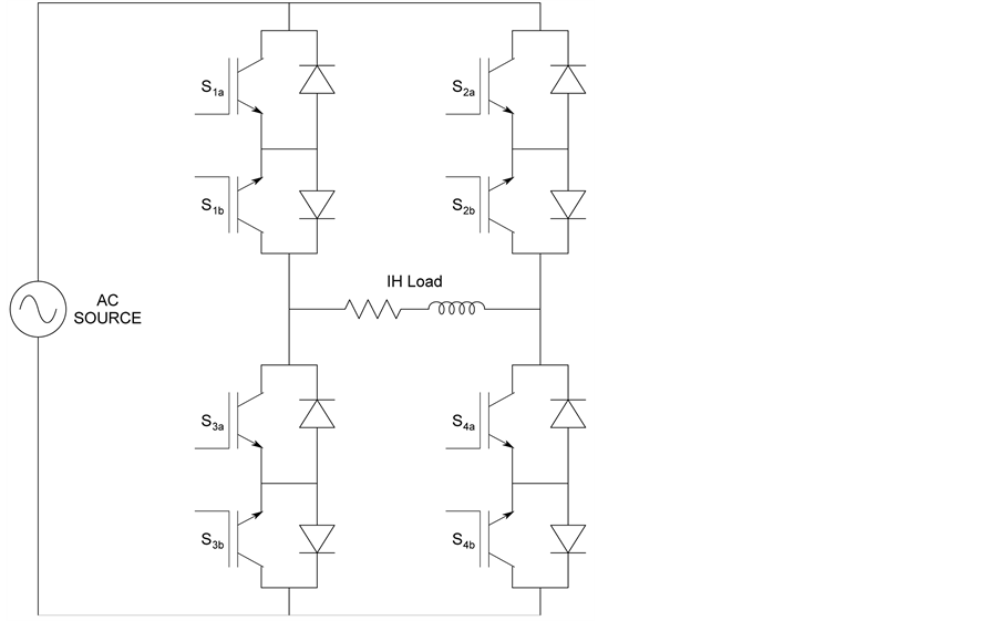
Gola and Idrish experimented the SPMC with AC source Vi having four bidirectional switches namely S1a, S1b, S2a, S2b, S3a, S3b, S4a and S4b, with the Induction Heating load is shown in Figure 2 [10] . Zuckerberger proposed the Single Phase Matrix Converter (SPMC) and consists of four bidirectional switches, such as S1a, S1b, S2a and S2b are connecting the input lines to output lines directly through the intersections discussed in detail in the block diagram [11] .
The commutation of these switches is difficult than the VSI and CSI AC-DC-AC converters due to the absence of freewheeling path in bidirectional switch configuration. As a result commutation of switches has to be actively controlled at any time instant with respect to two basic rules [12] . Modes of Operation of the Single Phase Matrix Converter (SPMC) consisting of eight switches is designed in a matrix form of four switching blocks in a bidirectional switching pattern as shown in Figure 1. Each switching block consists of two switches connected in anti-parallel direction as shown in Figure 2 with a recovery diode for each switch [13] . The output of the matrix converter is connected to the inductive heating system which is indicated by load as shown in Figure 1.
The switching pattern of the Matrix Converter switches for a constant input supply frequency of 50 Hz is given in Table 1 for various output frequencies of the Matrix Converter fed Induction Heating system. Table 1 gives switching pattern for output frequencies 25 Hz, 50 Hz and 100 Hz whereas output frequencies 1 kHz, 10 kHz and 100 kHz switching pattern have 40, 400 and 4000 time intervals respectively [14] for a single cycle of input and hence not represented in Table 1.
The switches S1, S3 and S2, S4 can be switched ON simultaneously as they will short circuit the input lines which will destroy the converter due to over current is shown in Figure 2. Similarly any switches S1, S3 and S2, S4 should not be switched OFF state simultaneously at any instant as it will open circuit the output phase which leads to the absence of path for the flow of inductive current leading to over voltages. This leads to a
Figure 1. Single phase matrix converter arrangement.
Figure 2. Basic block diagram of single phase matrix converter.
Table 1. Power flow switching sequence of the single phase matrix converter.
conflict as semiconductor switches cannot be switched instantaneously due to their propagation delay phenomenon and switch transient timings. The four basic operating modes of the Single Phase Matrix Converter based on power flow direction along the load for positive and negative half-cycle of the input power [15] .
There are basically four modes of operation, i.e., forward and reverse power flow for positive half cycle and forward and reverse power flow for negative half cycle as described. In mode 1 switching operation, switches S1a and S4a are switched ON by the Pulse Width Modulation (PWM) signal to conduct the positive half-cycle in forward direction to the load as shown in Figure 3.
In mode 2 switching operation, switches S2a and S3a are switched ON by the PWM
Figure 3. Power flow in mode 1 operation (S1a and S4a: ON).
signal to conduct the positive half-cycle in reverse direction to the load as shown in Figure 4.
In mode 3 switching operation, switches S2b and S3b are switched ON by the PWM signal to conduct the negative half-cycle in forward direction to the load as shown in Figure 5.
In mode 4 switching operation, switches S4b and S1b are switched ON by the PWM signal to conduct the negative half-cycle in reverse direction to the load as shown in Figure 6.
Based on the four operating sequences the Matrix Converter output frequency can be varied by varying the combination of the operating sequence of the switches and the switches describe the switching sequence of the Matrix Converter switches for an input voltage source frequency of 50 Hz to obtain variable frequency ranges.
Figure 7 shows the various output voltage waveform of the Single Phase Matrix Converter for various output frequency to a corresponding input frequency of 50 Hz.
a) Modeling of Single Phase to Single Phase Matrix Converter for Induction Heating
The Single Phase to Single Phase Matrix Converter module shown in Figure 8 which is designed with four modules of single bidirectional switches as shown in Figure 9. The designed Single Phase to Single Phase Matrix Converter is connected to an AC supply in the input and the output of the Matrix Converter is connected to an Induction Heating load [16] . The Single Phase to Single Phase Matrix Converter modeling in MATLAB/ Simulink environment is carried out starting with the modeling of bidirectional switches. The common emitter connected bidirectional switch arrangement of Single Matrix Converter switch module designed with MATLAB/Simulink environment [17] .
The modelling of the instantaneous input voltage is given by the Equation (1)
 (1)
(1)
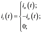
The instantaneous input current ii(t) is given by the Equation (2.2)
Figure 4. Power flow in mode 2 operation (S2a and S3a: ON).
Figure 5. Power flow in mode 3 operation (S2b and S3b: ON).
Figure 6. Power flow in mode 4 operation (S4b and S1b: ON).
Figure 7. Output frequencies of single phase matrix converter various output waveforms for 25 Hz, 50 Hz and 100 Hz corresponding to an input frequency of 50 Hz.
Figure 8. Circuit diagram of single phase to single phase matrix converter induction heating.
Figure 9. Simulation of single phase to single phase matrix converter for induction heating.
 (2)
(2)
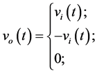
The instantaneous output voltage vo(t) is given by the Equation (3)
 (3)
(3)
The output voltage during any cycle is given by the Equation (4)
 (4)
(4)
where
 = output voltage during any kth cycle;
 = input voltage during any kth cycle.
The modulation index of any switch during any switching time is given by the Equations (5)-(8)
 (5)
(5)
 (6)
(6)


where


b) Simulink Model of Single Phase to Single Phase Matrix Converter for Induction Heating
The simulation of Single Phase Matrix Converter is builtup with four bidirectional IGBT switches connected in Common Emmitter Mode shows in Figure 8. The model of Single Phase to Single Phase Matrix Converter is consisting of single phase voltage source, Single Phase Matrix Converter and Single Phase Induction Heating load. Figure 9 shows the basic simulation circuit of Single Phase Matrix Converter switching arrangement [18] . Switching arrangement as a sub sytem which is connected with two IGBT back to back connection with two anti-parellel diodes as shown in Figure 10.
3. PID Controller for the Proposed Converter
The control signal from the PID controller output is fed to the PWM signal generator which acts as modultaion index for the PWM generator to generate pulse width modulated signals for energising the Matrix Converter switches to produce Single phase output from the Matrix Converter.
Figure 10. Simulation of common emitter bidirectional single module of matrix converter switch.
The input AC supply is fed to the Matrix Converter which energizes the Induction heating system shown in Figure 11. The Matrix Converter switching pattern generates nine switching pulse sequence in PWM mode block diagram stated in Figure 12. The load current or the output current of the Matrix Converter is compared with the reference value to produce the error (e) in output current. The change in error (ce) is calibrated and the error (e) and change in error (ce) are fed as inputs to the PID Controller. The PID controller produces a corresponding output signal for this input which is the control signal or modulation index for the pulse width modulation generator [19] . The pulse width modulation signal generator produces corresponding PWM signals for energizing the Matrix Converter through the bidirectional switches [20] .
4. Results and Discussions
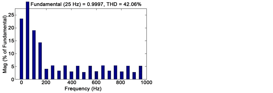
The results obtained from PID controlled Single Phase to Single Phase Matrix Converter for Induction Heating for various operating frequencies from 25 Hz to 100 kHz is presented in following figures. Figure 13(a) shows the input voltage and output voltage for operating frequency of 25 Hz and Figure 13(b) shows the corresponding output current for the Single Phase Induction Heating load rated for 230 V, 2.25 A. Figure 13(c) shows the THD measured for the corresponding operating frequency output. A THD of 42.06 is being measured for 25 Hz output frequency.
Figure 11. Block diagram of PID controller for single phase to single phase matrix converter.
Figure 12. Simulation of PID controller for single phase to single phase matrix converter.


Figure 13. (a) PID control of single phase to single phase matrix converter input and output voltage waveform for fo = 25 Hz; (b) PID control of single phase to single phase matrix converter output current waveform for fo = 25 Hz; (c) PID control of single phase to single phase matrix converter total harmonic distortion for fo = 25 Hz.
Figure 14(a) shows the input voltage and output voltage for operating frequency of 50 Hz and Figure 14(b) shows the corresponding output current for the Single Phase Matrix Converter for Induction Heating system load. Figure 14(c) depicts the Total


Figure 14. (a) PID Control of single phase to single phase matrix converter input and output voltage waveform for fo = 50 Hz; (b) PID control of single phase to single phase matrix converter output current waveform for fo = 50 Hz; (c) PID control of single phase to single phase matrix converter total harmonic distortion for fo = 50 Hz.
Harmonic Distortion (THD) measured for the corresponding operating frequency output. A THD of 37.52 is being measured for 50 Hz output frequency. Moreover the current and voltage waveforms are in phase which shows the unity power factor.
Figure 15(a) shows the input voltage and output voltage for operating frequency of 100 Hz and Figure 15(b) shows the corresponding output current for the Single Phase Induction Heating system load.


Figure 15. (a) PID control of single phase to single phase matrix Hz converter output current waveform for fo = 25; (b) PID control of single phase to single phase matrix converter input and output voltage waveform for fo = 100 Hz; (c) PID control of single phase to single phase matrix converter total harmonic distortion for fo = 100 Hz.
Figure 15(c) depicts the THD measured for the corresponding operating frequency output. A THD of 27.14 is being measured for 100 Hz output frequency.
Hence the frequency study of the described input and the corresponding output plotted and discussed. Table 2 represents the THD measured for the various operating frequencies in the PID controller based Single Phase Matrix Converter for Induction Heating.
Figure 16 shows the graph for Total Harmonic Distortion vs various operating frequencies for the proposed system.
As stated frequency and the Total Harmonic Distortion and different frequency relationship of PID Controller based Single Phase Matrix Converter for Induction Heating are compared.
5. Conclusion
The single phase matrix converter powered by single phase source is modeled in MATLAB/Simulink and performance analysis of the converter is carried out with linear proposed PID controller. The PID controller based single phase to single phase matrix converter results were explained and discussed. Simulation is carried out for specified frequencies such as 25 Hz, 50 Hz and 100 Hz. The output of the converter presented and comparison of total harmonic distortion of the PID controller based single phase matrix converter is also presented. The performance of single phase matrix converter
Figure 16. Total Harmonic distortion vs frequency plot for PID control of single phase to single phase matrix converter for induction heating.
Table 2. Measurement of THD for various operating frequencies of PID controlled single phase to single phase matrix converter.
controlled by PID controller is analyzed and they exhibit low Total Harmonic Distortion (THD). The proposed PID controller based matrix converters demonstrate the robust operation for induction heating load.
Cite this paper
Umasankar, Dr.P. and Senthil Kumar, Dr.S. (2016) A General Approach for Direct Conversion of Single Phase AC to AC Converter for Induction Heating System. Circuits and Systems, 7, 3896-3910. http://dx.doi.org/10.4236/cs.2016.711325
References
- 1. Acero, J. (2010) Domestic Induction Appliances. IEEE Industry Applications Magazine, 16, 39-47.
http://dx.doi.org/10.1109/MIAS.2009.935495 - 2. Acero, J., Burdio, J.M., Barragan, L.A., Navarro, D., Alonso, R., Garcia, J.R., Monterde, F., Hernandez, P., Llorente, S. and Garde, I. (2008) The Domestic Induction Heating Appliance: An Overview of Recent Research. Twenty-Third Annual IEEE Applied Power Electronics Conference and Exposition, 651-657.
- 3. Gola, A.K. and Agarwal, V. (2009) Implementation of an Efficient Algorithm for a Single Phase Matrix Converter. Journal of Power Electronics, 9, 198-206.
- 4. Akagi, H., Sawae, T. and Nabae, A. (1986) 130 kHz, 7.5 kW Current Source Inverter Using Static Transistors for Induction Heating Applications. Proceedings of the Power Electronics Specialist Conference (PESC), Vancouver, 395-400.
- 5. Alesina, A. and Venturini, M. (1981) Solid-State Power Conversion: A Fourier Analysis Approach to Generalized Transformer Synthesis. IEEE Transactions on Circuits and Systems, 28, 319-330.
http://dx.doi.org/10.1109/TCS.1981.1084993 - 6. Alesina, A. and Venturini, M. (1988) Intrinsic Amplitude Limits and Optimum Design of 9-Switches Direct PWM AC-AC Converters. 19th Annual IEEE Power Electronics Specialists Conference, 2, 1284-1291.
http://dx.doi.org/10.1109/PESC.1988.18273 - 7. Alesina, A. and Venturini, M. (1989) Analysis and Design of Optimum-Amplitude Nine- Switch Direct AC-AC Converters. IEEE Transactions on Power Electronics, 4, 101-112.
http://dx.doi.org/10.1109/63.21879 - 8. Almazán, F., Lucía, O., Acero, J., Burdío, J.M. and Carretero, C. (2011) A New Multiple- Output Resonant Matrix Converter Topology Applied To Domestic Induction Heating. 1-12.
- 9. Baharom, R., Hamzah, N.R. and Hamzah, M.K. (2011) Advanced Single-Phase AC-DC Converter Using Single-Phase Matrix Converter Topology. IEEE International Conference on Electrical, Control and Computer Engineering, 21-22 June 2011, 33-38.
http://dx.doi.org/10.1109/inecce.2011.5953845 - 10. Idris, Z., Hamzah, M.K. and Saidon, M.F. (2006) Implementation of SPMC as a Direct AC-AC Converter with Commutation Strategies. IEEE PESC, 2240-2246.
- 11. Zuckerberger, A., Weinstock, D. and Alexandrovitz, A. (1997) Single-Phase Matrix Converter. IET Electric Power Applications, 144, 235-240.
http://dx.doi.org/10.1049/ip-epa:19970848 - 12. Baharom, R., Hashim, H., Seroji, M.N. and Hamzah, M.K. (2008) A New Single-Phase Dual Converter Using Single-Phase Matrix Converter. 3rd IEEE Conference onIndustrial Electronics and Applications, 3-5 June 2008, 1151-1156.
http://dx.doi.org/10.1109/iciea.2008.4582699 - 13. Mohammad Noor, S.Z., Baharom, R., Hamzah, M.K. and Hamzah, N.R. (2009) Safe- Commutation Strategy for Controlled Rectifier Operation Using Single-Phase Matrix Converter. International Conference on Power Electronics and Drive Systems, 1026-1029.
- 14. Barakati, S.M., Kazerani, M. and Aplevich, J.D. (2006) A Dynamic Model for a Wind Turbine System Including a Matrix Converter. Proceedings of IASTED, PES2007, 1-8.
- 15. Barakati, S.M., Kazerani, M. and Aplevich, J.D. (2008) An Overall Model for a Matrix Converter. IEEE International Symposium on Industrial Electronics, 30 June-2 July 2008.
http://dx.doi.org/10.1109/ISIE.2008.4677115 - 16. Tudbury, C.A. (1960) Basics of Induction Heating. Vol. I, John F. Rider Publisher, Inc., New York.
- 17. Lucía, O., Burdío, J.M. and Barragán, L.A. (2010) Series-Resonant Multi-Inverter for Multiple Induction Heaters. IEEE Transactions on Power Electronics, 24, 2860-2868.
http://dx.doi.org/10.1109/TPEL.2010.2051041 - 18. Corticelli, G. (1991) 3 kW at 2.2 MHz with a Resonant MOSFET Inverter. Proceedings of the European Conference on Power Electronics and Applications, 4, 158-161.
- 19. Curtis, F.W. (1950) High Frequency Induction Heating. McGraw Hill.
- 20. Gola, K. and Agarwal, V. (2009) Implementation of an Efficient Algorithm for a SPMC. Journal of Power Electron, 9, 198-206.
Nomenclatures


m1, m2: Modulation index of PWM signals
fS: Switching frequency
TS: Switching cycle time
Submit or recommend next manuscript to SCIRP and we will provide best service for you:
Accepting pre-submission inquiries through Email, Facebook, LinkedIn, Twitter, etc.
A wide selection of journals (inclusive of 9 subjects, more than 200 journals)
Providing 24-hour high-quality service
User-friendly online submission system
Fair and swift peer-review system
Efficient typesetting and proofreading procedure
Display of the result of downloads and visits, as well as the number of cited articles
Maximum dissemination of your research work
Submit your manuscript at: http://papersubmission.scirp.org/
Or contact cs@scirp.org


