M. ZAHER, S. CETINKUNT
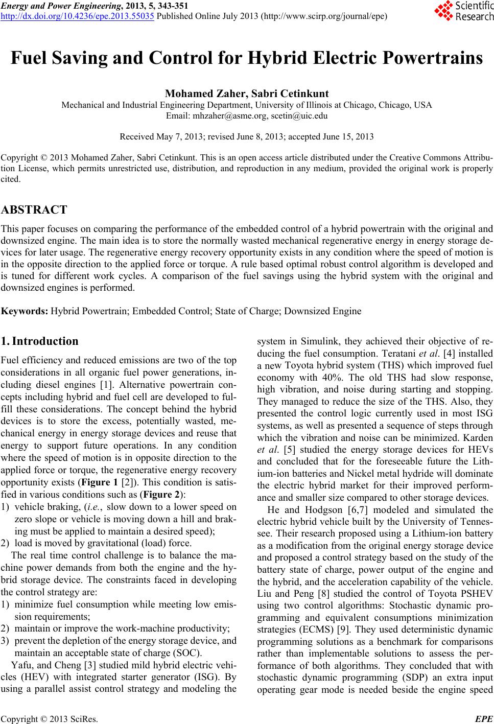
350
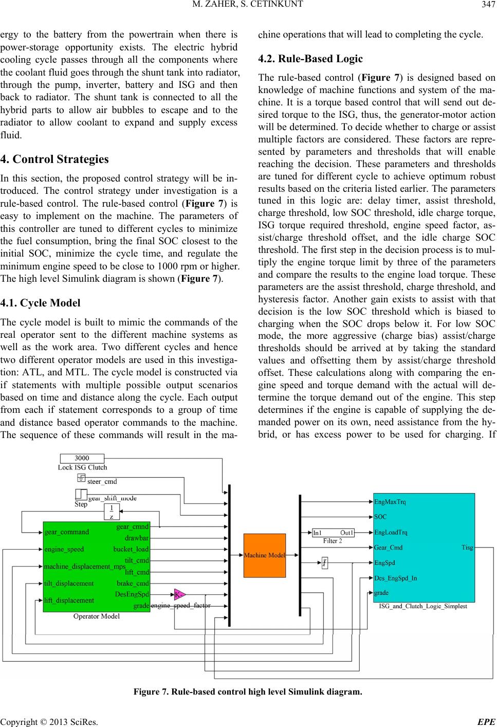
Table 1. Aggressive truck loading baseline and hybrid com-
parison.
Machine Cycle Time
(sec) Fuel
(grams)
Productivity
(%) Fuel consumption
(%)
Baseline 32.15 344.6
9 Liters
Hybrid 31.7 321.7 1.4 −6.65
7 Liters
Hybrid 32.1 275.7 0.16 −20
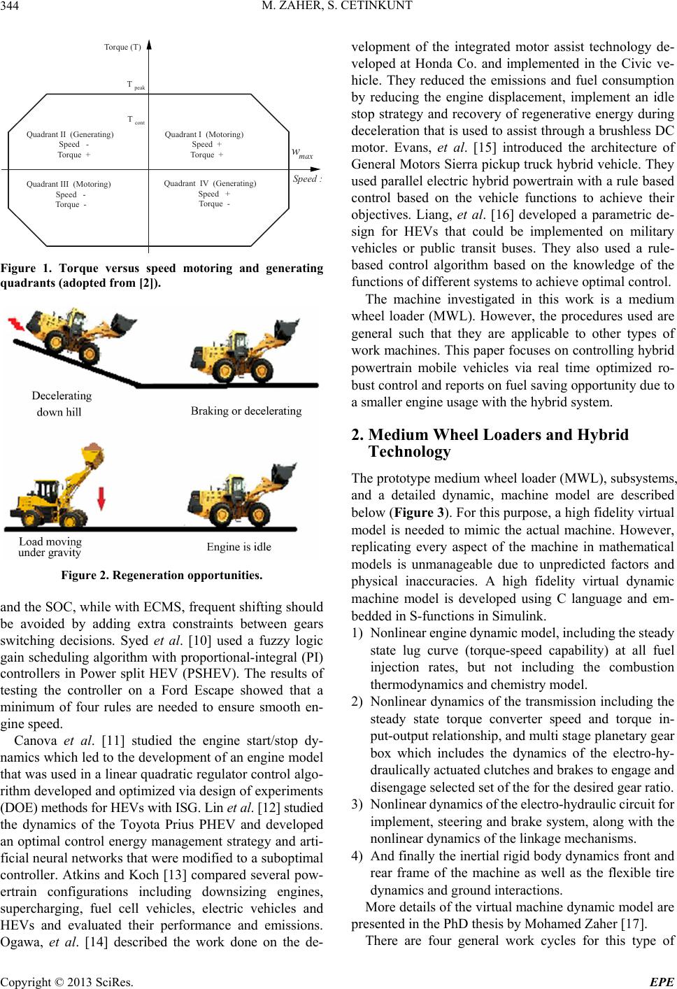
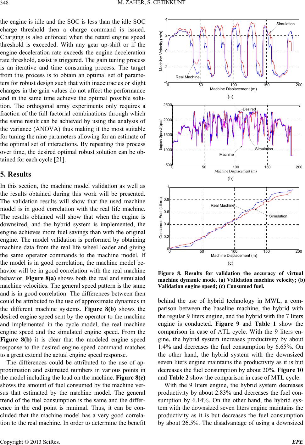
Table 2. Moderate truck loading baseline and hybrid com-
parison.
Machine Cycle Time
(sec) Fuel
(grams)
Productivity
(%) Fuel c onsumption
(%)
Baseline 37.7 413.17
9 Liters
Hybrid 38.8 387.8 −2.83 −6.14
7 Liters
Hybrid 37.5 303.9 0.53 −26.45
engine is that if the battery runs out of charge, the engine
may not be able to support the machine functions. On the
other hand, the hybrid with the original engine doesn’t
provide the desired fuel consumption reduction.
6. Conclusion
The implementation of the hybrid system on the medium
wheel loader is expected to maintain the productivity of
the machine within acceptable range. The usage of the
hybrid system with a 7 liters engine is expected to reduce
the fuel consumption on the machine by 20% - 27% at
the simulated cycles. The usage of the hybrid system
with the 9 liters engine is expected to reduce the fuel
consumption on the machine by 6% - 7% at the simu-
lated cycles.
REFERENCES
[1] C. D. Rakopoulos and E. G. Giakoumis, “Diesel Engine
Transient Operation: Principles of Operation and Simula-
tion Analysis,” Springer, Berlin, 2009.
[2] S. Cetinkunt, “Mechatronics,” John Wiley and Sons, Ho-
boken, 2007.
[3] Z. Yafu and C. Cheng, “Study on the Powertrain for ISG
Mild Hybrid Electric Vehicle,” IEEE Vehicle Power and
Propulsion Conference, Harbin, 3-5 September 2008, pp.
1-5.
[4] T. Teratani, K. Kuramochi, H. Nakao, T. Tachibana, K.
Yagi and S. Abou, “Development of Toyota Mild Hybrid
Vehicle (THS-M) with 42V Power Net,” IEEE Interna-
tional Electric Machines and Drives Conference, 1-4 June
2003, pp. 3-10.
[5] E. Karden, S. Ploumen, B. Fricke, T. Miller and K. Sny-
der, “Energy Storage Devices for Future Hybrid Electric
Vehicles,” Journal of Power Sources, Vol. 168, No. 1,
2007, pp. 2-11. doi:10.1016/j.jpowsour.2006.10.090
[6] X. He and J. W. Hodgson, “Modeling and Simulation for
Hybrid Electric Vehicles—Part I: Modeling,” IEEE
Transaction on Intelligent Transportation Systems, Vol. 3,
No. 4, 2002, pp. 235-243. doi:10.1109/TITS.2002.807781
[7] X. He and J. W. Hodgson, “Modeling and Simulation for
Hybrid Electric Vehicles—Part II: Simulation,” IEEE
Transaction on Intelligent Transportation Systems, Vol. 3,
No. 4, 2002, pp. 244-251.
[8] J. Liu and H. Peng, “Modeling and Control of a Power-
Split Hybrid Vehicle,” IEEE Transactions on Control
Systems Technology, Vol. 16, No. 6, 2008, pp. 1242-1251.
doi:10.1109/TCST.2008.919447
[9] G. Paganelli, et al., “Optimizing Control Strategy for
Hybrid Fuel Cell Vehicle,” SAE Warrendale, Warrendale,
Technical Report 2002-01-0102, 2002.
[10] F. U. Syed, et al., “Rule-Based Fuzzy Gain-Scheduling PI
Controller to Improve Engine Speed and Power Behavior
in Power-Split Hybrid Electric Vehicle,” IEEE Transac-
tions on Vehicle Technology, Vol. 58, No. 1, 2009, pp.
69-84. doi:10.1109/TVT.2008.923690
[11] M. Canova, et al., “On the Control of Engine Start/Stop
Dynamics in a Hybrid Electric Vehicle,” Journal of Dy-
namic Systems, Measurement, and Control, Vol. 131, No.
6, 2009, 12 Pages.
[12] X. Lin, et al., “Optimal Energy Management for a Plug-In
Hybrid Electric Vehicle: Real-Time Controller,” Ameri-
can Control Conference, Baltimore, 30 June-2 July 2010,
PP. 5037-5042.
[13] M. J. Atkins and C. R. Koch, “A Well-to-Wheel Com-
parison of Several Powertrain Technologies,” SAE Ad-
vanced Hybrid Vehicle Powertrains, 2003, pp. 1-9.
doi:10.4271/2003-01-0081
[14] H. Ogawa, M. Matsuki and T. Eguchi, “Development of a
Powertrain for the Hybrid Automobile—The Civic Hy-
brid,” SAE Advanced Hybrid Vehicle Powertrains, 2003,
pp. 11-22. doi:10.4271/2003-01-0083
[15] D. G. Evans, M. E. Polom, S. G. Poulos, K. D. Van Maanen
and T. H. Zarger, “Powertrain Architecture and Controls
Integration for GM’s Hybrid Full-Size Pickup Truck,”
SAE Advanced Hybrid Vehicle Powertrains, 2003, pp.
33-44.
[16] C. Liang, W. Weihua and W. Qingnian, “Energy Man-
agement Strategy and Parametric Design for Hybrid Elec-
tric Military Vehicle,” SAE Advanced Hybrid Vehicle
Powertrains, 2003, pp. 45-50. doi:10.4271/2003-01-0086
[17] M. Zaher, “Real Time Energy Management Control Stra-
tegies for Hybrid Powertrains,” Ph.D. Thesis, University
of Illinois at Chicago, Chicago, 2013.
[18] F Croce, “Optimal Design of Powertrain and Hydraulic
Implement Systems for Construction Equipment Applica-
tions,” Ph.D. Thesis, University of Illinois at Chicago,
Chicago, 2010.
[19] M. Ehsani, et al., “Modern Electric, Hybrid Electric, and
Fuel Cell Vehicles: Fundamentals, Theory, and Design
Second Edition,” CRC Press, Taylor and Francis Group,
Boca Raton, London, 2010.
Copyright © 2013 SciRes. EPE