Paper Menu >>
Journal Menu >>
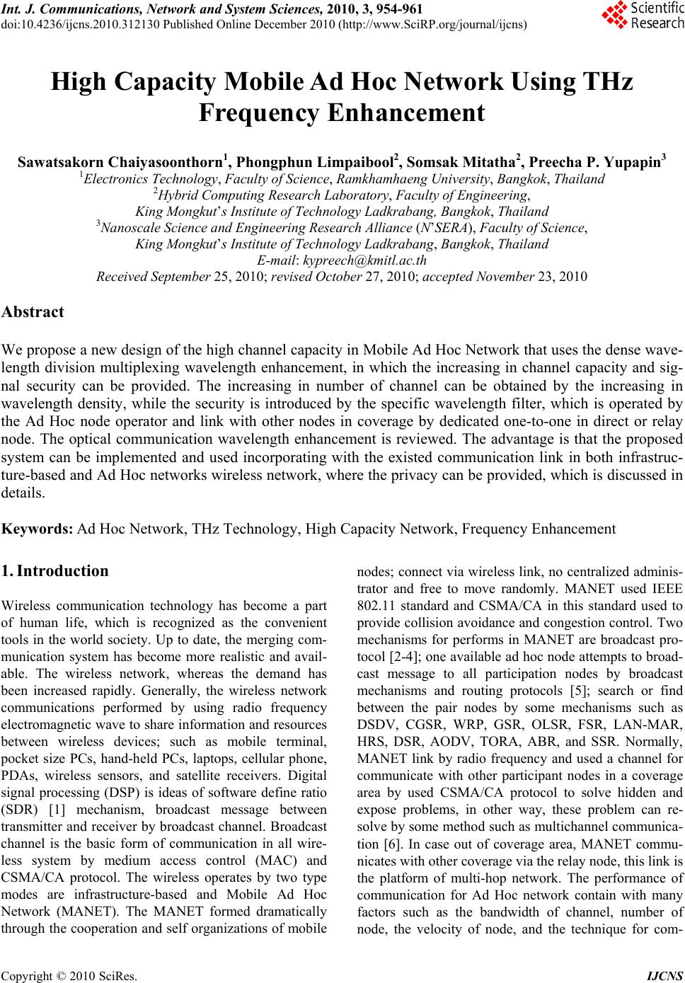 Int. J. Communications, Network and System Sciences, 2010, 3, 954-961 doi:10.4236/ijcns.2010.312130 Published Online December 2010 (http://www.SciRP.org/journal/ijcns) Copyright © 2010 SciRes. IJCNS High Capacity Mobile Ad Hoc Network Using THz Frequency Enhancement Sawatsakorn Chaiyasoonthorn1, Phongphun Limpaibool2, Somsak Mitatha2, Preecha P. Yupapin3 1Electronics Technology, Faculty of Science, Ramkhamhaeng University, Ba ngkok, Thailand 2Hybrid Computing Research Laboratory, Faculty of Engineering, King Mongkut’s Institute of Technology Ladkrabang, Bangkok, Thailand 3Nanoscale Science and Engineering Research Alliance (N’SERA), Faculty of Science, King Mongkut’s Institute of Technology Ladkrabang, Bangk ok, Thailand E-mail: kypreech@kmitl.ac.th Received September 25, 2010; revised October 27, 2010; accepted November 23, 2010 Abstract We propose a new design of the high channel capacity in Mobile Ad Hoc Network that uses the dense wave- length division multiplexing wavelength enhancement, in which the increasing in channel capacity and sig- nal security can be provided. The increasing in number of channel can be obtained by the increasing in wavelength density, while the security is introduced by the specific wavelength filter, which is operated by the Ad Hoc node operator and link with other nodes in coverage by dedicated one-to-one in direct or relay node. The optical communication wavelength enhancement is reviewed. The advantage is that the proposed system can be implemented and used incorporating with the existed communication link in both infrastruc- ture-based and Ad Hoc networks wireless network, where the privacy can be provided, which is discussed in details. Keywords: Ad Hoc Network, THz Technology, High Capacity Network, Frequency Enhancement 1. Introduction Wireless communication technology has become a part of human life, which is recognized as the convenient tools in the world society. Up to date, the merging com- munication system has become more realistic and avail- able. The wireless network, whereas the demand has been increased rapidly. Generally, the wireless network communications performed by using radio frequency electromagnetic wave to share information and resources between wireless devices; such as mobile terminal, pocket size PCs, hand-held PCs, laptops, cellular phone, PDAs, wireless sensors, and satellite receivers. Digital signal processing (DSP) is ideas of software define ratio (SDR) [1] mechanism, broadcast message between transmitter and receiver by broadcast channel. Broadcast channel is the basic form of communication in all wire- less system by medium access control (MAC) and CSMA/CA protocol. The wireless operates by two type modes are infrastructure-based and Mobile Ad Hoc Network (MANET). The MANET formed dramatically through the cooperation and self organizations of mobile nodes; connect via wireless link, no centralized adminis- trator and free to move randomly. MANET used IEEE 802.11 standard and CSMA/CA in this standard used to provide collision avoidance and congestion control. Two mechanisms for performs in MANET are broadcast pro- tocol [2-4]; one available ad hoc node attempts to broad- cast message to all participation nodes by broadcast mechanisms and routing protocols [5]; search or find between the pair nodes by some mechanisms such as DSDV, CGSR, WRP, GSR, OLSR, FSR, LAN-MAR, HRS, DSR, AODV, TORA, ABR, and SSR. Normally, MANET link by radio frequency and used a channel for communicate with other participant nodes in a coverage area by used CSMA/CA protocol to solve hidden and expose problems, in other way, these problem can re- solve by some method such as multichannel communica- tion [6]. In case out of coverage area, MANET commu- nicates with other coverage via the relay node, this link is the platform of multi-hop network. The performance of communication for Ad Hoc network contain with many factors such as the bandwidth of channel, number of node, the velocity of node, and the technique for com- 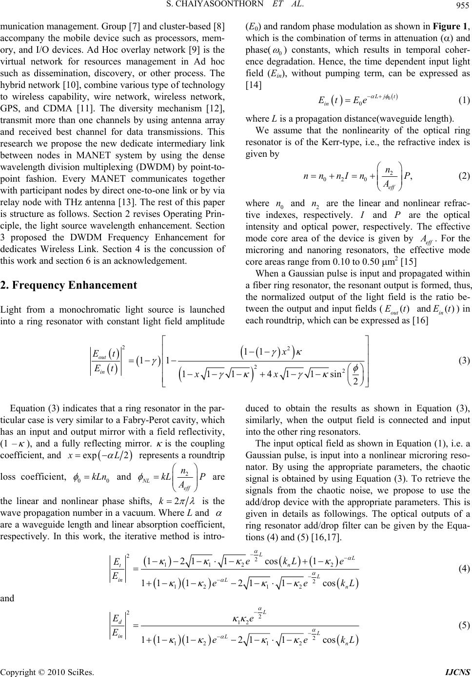 S. CHAIYASOONTHORN ET AL. 955 munication management. Group [7] and cluster-based [8] accompany the mobile device such as processors, mem- ory, and I/O devices. Ad Hoc overlay network [9] is the virtual network for resources management in Ad hoc such as dissemination, discovery, or other process. The hybrid network [10], combine various type of technology to wireless capability, wire network, wireless network, GPS, and CDMA [11]. The diversity mechanism [12], transmit more than one channels by using antenna array and received best channel for data transmissions. This research we propose the new dedicate intermediary link between nodes in MANET system by using the dense wavelength division multiplexing (DWDM) by point-to- point fashion. Every MANET communicates together with participant nodes by direct one-to-one link or by via relay node with THz antenna [13]. The rest of this paper is structure as follows. Section 2 revises Operating Prin- ciple, the light source wavelength enhancement. Section 3 proposed the DWDM Frequency Enhancement for dedicates Wireless Link. Section 4 is the concussion of this work and section 6 is an acknowledgement. 2. Frequency Enhancement Light from a monochromatic light source is launched into a ring resonator with constant light field amplitude (E0) and random phase modulation as shown in Figure 1, which is the combination of terms in attenuation () and phase( 0 ) constants, which results in temporal coher- ence degradation. Hence, the time dependent input light field (Ein), without pumping term, can be expressed as [14] 0 0 L jt in Et Ee (1) where L is a propagation distance(waveguide length). We assume that the nonlinearity of the optical ring resonator is of the Kerr-type, i.e., the refractive index is given by 2 02 0, eff n nn nInP A (2) where 0 and 2 are the linear and nonlinear refrac- tive indexes, respectively. n n I and are the optical intensity and optical power, respectively. The effective mode core area of the device is given by eff P A . For the microring and nanoring resonators, the effective mode core areas range from 0.10 to 0.50 m2 [15] When a Gaussian pulse is input and propagated within a fiber ring resonator, the resonant output is formed, thus, the normalized output of the light field is the ratio be- tween the output and input fields ( and) in each roundtrip, which can be expressed as [16] () out Et () in Et 22 22 11 11 111 411sin 2 out in x Et Et xx (3) Equation (3) indicates that a ring resonator in the par- ticular case is very similar to a Fabry-Perot cavity, which has an input and output mirror with a field reflectivity, (1 –), and a fully reflecting mirror. is the coupling coefficient, and exp 2x L 0 represents a roundtrip loss coefficient, 0 kLn and 2 NL eff n kL P A are the linear and nonlinear phase shifts, 2k is the wave propagation number in a vacuum. Where L and are a waveguide length and linear absorption coefficient, respectively. In this work, the iterative method is intro- duced to obtain the results as shown in Equation (3), similarly, when the output field is connected and input into the other ring resonators. The input optical field as shown in Equation (1), i.e. a Gaussian pulse, is input into a nonlinear microring reso- nator. By using the appropriate parameters, the chaotic signal is obtained by using Equation (3). To retrieve the signals from the chaotic noise, we propose to use the add/drop device with the appropriate parameters. This is given in details as followings. The optical outputs of a ring resonator add/drop filter can be given by the Equa- tions (4) and (5) [16,17]. 22 112 2 2 121 2 1211cos 1 11 1211cos L L n t L in Ln ekL e E Eee kL (4) and 22 12 2 121 2 11 1211cos L d L in Ln Ee Eee kL (5) Copyright © 2010 SciRes. IJCNS  956 S. CHAIYASOONTHORN ET AL. Figure 1. A schematic of a Gaussian soliton generation system, where Rs: ring radii, s: coupling coefficients, Rd: an add/drop ring radius, Aeff: Effective areas, MRR: Microring resonator, NRR: Nanoring resonator, K42 and K42 are add/drop coupling coefficients. where Et and Ed represents the optical fields of the throughput and drop ports respectively. The transmitted output can be controlled and obtained by choosing the suitable coupling ratio of the ring resonator, which is well derived and described by reference [17]. Where eff kn represents the propagation constant, eff is the effective refractive index of the waveguide, and the circumference of the ring is n 2LR , here is the radius of the ring. When the chaotic noise cancellation can be managed by using the specific parameters of the add/drop device, which the required signals at the spe- cific wavelength band can be filtered and retrieved. К1and К2 are coupling coefficient of add/drop filters, R 2 n k is the wave propagation number for in a vacuum, and the waveguide (ring resonator) loss is = 0.5 dBmm-1. The fractional coupler intensity loss is = 0.1. In the case of add/drop device, the nonlinear refrac- tive index is neglected. 3. High Capacity Ad Hoc Network Using Wireless Link MANET is an autonomous node and independent re- sources management, majority used a channel for link all nodes by using CSMA/CA to access management. In this paper, we propose new platform for link wireless node by using a link per node (1-1), show in Figure 1. From Figure 2, depict the Ad Hoc link model, (a) nodes A, B, and C can communicate with all other nodes or in coverage, in this cast A link to B directly, B link to C directly, and A link to C by directly. From Figure 2(b), all nodes not in coverage, node A, B, and C are in cov- erage, nodes C and D are in coverage, and nodes D, C, and E are in coverage. From Figure 1(c), show diagram for link by 1-1 of node A, node A can link to node B directly, node A can link to node C directly, node A can link to node B directly, but node A cannot link to nodes E and F directly due to out of coverage. In this case, we propose virtual direct link by using relay node, node A link to node E and F by used relay nodes C and D. Node A link to node E by using a channel via relay node C relay node D and in this case node A use four cannel for link in a time. From Figures 1 and 3, in principle, light pulse is sliced to be the discrete signal and amplified within the first ring, where more signal amplification can be ob- tained by using the smaller ring device (second ring). Finally, the required signals can be obtained via a drop port of the add/drop filter. In operation, an optical field in the form of Gaussian pulse from a laser source at the specified center wavelength (frequency) is input into the system. In practice, the maximum frequency that can be confined within the optical waveguide has been in- creased by using the composite of materials known as meta-materials [18], which is shown that the wavelength close to few mm (THz region) can be confined within the Copyright © 2010 SciRes. IJCNS  S. CHAIYASOONTHORN ET AL. 957 Figure 2. (a) Link 1-1 by direct node, (b) Link 1-1 via relay node, and (c) Diagra m for node A link to all node (B, C, D, E, and F). Figure 3. Ad Hoc wireless link model, where Rs: ring radii, s: coupling coefficients, Rd: an add/drop ring radius, Aeff: Effec- tive areas, MRR: Microring resonator, NRR: Nanoring resonator, K42 and K42 are add/drop coupling coefficients. waveguide. In operation, light pulse is sliced to be the discrete signal and amplified within the first ring, where more signal amplification can be obtained by using the smaller ring device (second ring) as shown in Figure 1. Finally, the required signals can be obtained via a drop port of the add/drop filter. An optical field in the form of Gaussian pulse from a laser source at the specified center frequency is input into the system. From Figure 3, the Gaussian pulse with center frequency (f0) at 3.0 THz, pulse width (Full Width at Half Maximum, FWHM) of Copyright © 2010 SciRes. IJCNS  958 S. CHAIYASOONTHORN ET AL. 20 ns, peak power at 2 W is input into the system as shown in Figure 4(a). The large bandwidth signals can be seen within the first microring device, and shown in Figure 4(b). The suitable ring parameters are used, for instance, ring radii R1 = 15.0 μm, R2 = R3 = 9.0 μm, and Rd = 50.0 μm. In order to make the system associate with the practical device [19,20], the selected parameters of the system are fixed to n0 = 3.34 (InGaAsP/InP), Aeff = 0.50 m2 and 0.25 m2 for a microring and add/drop ring resonator, respectively, = 0.5 dBmm-1, = 0.1. In this investigation, the coupling coefficient (kappa, ) of the microring resonator is ranged from 0.10 to 0.96. The nonlinear refractive index of the microring used is n2 = 2.2 × 10⁻¹⁷ m2/W. In this case, the attenuation of light propagates within the system (i.e. wave guided) used is 0.5 dBmm-1. After light is input into the system, the Gaussian pulse is chopped (sliced) into a smaller signal spreading over the spectrum due to the nonlinear effects [16], which is shown in Figure 4(b). The large bandwidth signal is generated within the first ring device. In applications, the specific input or output frequencies can be used and gen- erated, where the suitable parameters are used and shown in the figures. The similar manner is as shown in Figures 5-7, where the different parameters are the Rd radii and coupling coefficients, where the small FSR is obtained. In Figure 5, results of the THz frequency band with the center frequency at 3 THz, where (a) the input Gaussian pulse, (b) the large bandwidth signal, (c) the filtering and amplifying signals, (d) output frequency band, (e) and (f )are the drop port signals, (g) and (h)are the through port signals. 4. Conclusions We have shown that the multi frequency bands can be generated by using a Gaussian pulse propagating within the microring resonator system, which can be simulta- neous link within a single device and available for the extended multi switching application with the frequency relay at the THz band. The Mirroring resonators system embedded in mobile node to generate bandwidth for serve two communication styles are direct communica- tion and multi-hop communication by relay service. This can be used for wireless network with the existed public networks or the Ad Hoc network. Figure 4. Results of the THz frequency band wi th the center frequency at 3THz, where (a) the input Gaussian pulse, (b) the large bandwidth signal, (c) the filtering and amplifying signals, (d) output frequency band, (e) and (f) are the drop port sig- nals, (g) and (h) are the through port signals. Copyright © 2010 SciRes. IJCNS  S. CHAIYASOONTHORN ET AL. 959 Figure 5. Results of the THz frequency band wi th the center frequency at 3THz, where (a) the input Gaussian pulse, (b) the large bandwidth signal, (c) the filtering and amplifying signals, (d) output frequency band, (e) and (f) are the drop port sig- nals, (g) and (h) are the through port signals. Figure 6. Results of the THz frequency band w ith the center frequency at 3 THz, where (a) the input Gaussian pulse , (b) the large bandwidth signal, (c) the filtering and amplifying signals, (d) output frequency band, (e) and (f )are the drop port sig- nals, (g) and (h)are the through port signals. Copyright © 2010 SciRes. IJCNS 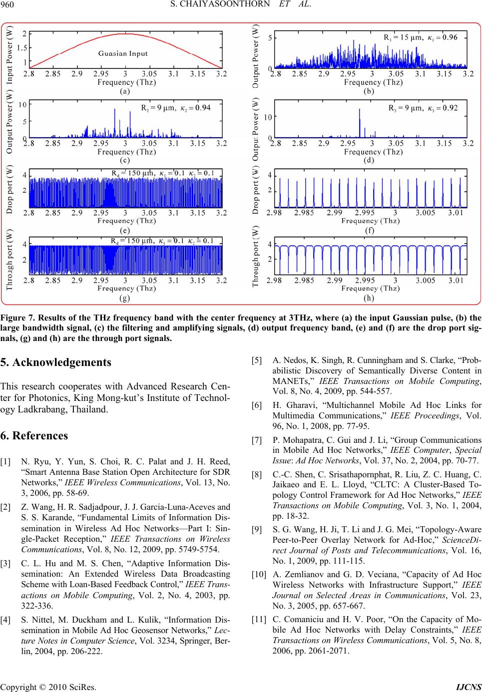 S. CHAIYASOONTHORN ET AL. Copyright © 2010 SciRes. IJCNS 960 Figure 7. Results of the THz frequency band wi th the center frequency at 3THz, where (a) the input Gaussian pulse, (b) the large bandwidth signal, (c) the filtering and amplifying signals, (d) output frequency band, (e) and (f) are the drop port sig- nals, (g) and (h) are the through port signals. 5. Acknowledgements [5] A. Nedos, K. Singh, R. Cunningham and S. Clarke, “Prob- abilistic Discovery of Semantically Diverse Content in MANETs,” IEEE Transactions on Mobile Computing, Vol. 8, No. 4, 2009, pp. 544-557. This research cooperates with Advanced Research Cen- ter for Photonics, King Mong-kut’s Institute of Technol- ogy Ladkrabang, Thailand. [6] H. Gharavi, “Multichannel Mobile Ad Hoc Links for Multimedia Communications,” IEEE Proceedings, Vol. 96, No. 1, 2008, pp. 77-95. 6. References [7] P. Mohapatra, C. Gui and J. Li, “Group Communications in Mobile Ad Hoc Networks,” IEEE Computer, Special Issue: Ad Hoc Networks, Vol. 37, No. 2, 2004, pp. 70-77. [1] N. Ryu, Y. Yun, S. Choi, R. C. Palat and J. H. Reed, “Smart Antenna Base Station Open Architecture for SDR Networks,” IEEE Wireless Communications, Vol. 13, No. 3, 2006, pp. 58-69. [8] C.-C. Shen, C. Srisathapornphat, R. Liu, Z. C. Huang, C. Jaikaeo and E. L. Lloyd, “CLTC: A Cluster-Based To- pology Control Framework for Ad Hoc Networks,” IEEE Transactions on Mobile Computing, Vol. 3, No. 1, 2004, pp. 18-32. [2] Z. Wang, H. R. Sadjadpour, J. J. Garcia-Luna-Aceves and S. S. Karande, “Fundamental Limits of Information Dis- semination in Wireless Ad Hoc Networks—Part I: Sin- gle-Packet Reception,” IEEE Transactions on Wireless Communications, Vol. 8, No. 12, 2009, pp. 5749-5754. [9] S. G. Wang, H. Ji, T. Li and J. G. Mei, “Topology-Aware Peer-to-Peer Overlay Network for Ad-Hoc,” ScienceDi- rect Journal of Posts and Telecommunications, Vol. 16, No. 1, 2009, pp. 111-115. [3] C. L. Hu and M. S. Chen, “Adaptive Information Dis- semination: An Extended Wireless Data Broadcasting Scheme with Loan-Based Feedback Control,” IEEE Trans- actions on Mobile Computing, Vol. 2, No. 4, 2003, pp. 322-336. [10] A. Zemlianov and G. D. Veciana, “Capacity of Ad Hoc Wireless Networks with Infrastructure Support,” IEEE Journal on Selected Areas in Communications, Vol. 23, No. 3, 2005, pp. 657-667. [11] C. Comaniciu and H. V. Poor, “On the Capacity of Mo- bile Ad Hoc Networks with Delay Constraints,” IEEE Transactions on Wireless Communications, Vol. 5, No. 8, 2006, pp. 2061-2071. [4] S. Nittel, M. Duckham and L. Kulik, “Information Dis- semination in Mobile Ad Hoc Geosensor Networks,” Lec- ture Notes in Computer Science, Vol. 3234, Springer, Ber- lin, 2004, pp. 206-222.  S. CHAIYASOONTHORN ET AL. 961 [12] G. Jakllari, S. V. Krishnamurthy, M. Faloutsos and P. V. Krishnamurthy, “On Broadcasting with Cooperative Di- versity in Multi-Hop Wireless Networks,” IEEE Journal on Selected Areas in Communications, Vol. 25, No. 2, 2007, pp. 484-496. [13] A. Sharma and G. Singh, “Rectangular Microstirp Patch Antenna Design at THz Frequency for Short Distance Wireless Communication Systems,” Springer Journal of Infrared and Millimeter and Terahertz Waves, Vol. 30, No. 1, 2009, pp. 1-7. [14] D. Deng and Q. Guo, “Ince-Gaussian Solitons in Strongly Nonlocal Nonlinear Media,” Optics Letters, Vol. 32, No. 21, 2007, pp. 3206-3208. [15] Q. Xu and M. Lipson, “All-Optical Logic Based on Sili- con Micro-Ring Resonators,” Optics Express, Vol. 15, No. 3, 2007, pp. 924-929. [16] P. P. Yupapin and W. Suwancharoen, “Chaotic Signal Generation and Cancellation Using a Microring Resona- tor Incorporating an Optical Add/Drop Multiplexer,” Op- tics Communications, Vol. 280, No. 2, 2007, pp. 343-350. [17] P. P. Yupapin, P. Saeung and C. Li, “Characteristics of Complementary Ring-Resonator Add/Drop Filters Mod- eling by Using Graphical Approach,” Optics Communi- cations, Vol. 272, No. 1, 2007, pp. 81-86. [18] M. Fujii, J. Leuthold and W. Freude, “Dispersion Rela- tion and Loss of Subwavelength Confined Mode of Metal- Dielectri-Gap Optical Waveguides,” IEEE Photonics Tech- nology Letters, Vol. 21, No. 6, 2009, pp. 362-364. [19] Y. Kokubun, Y. Hatakeyama, M. Ogata, S. Suzuki and N. Zaizen, “Fabrication Technologies for Vertically Coupled Micro Ring Resonator with Multilevel Crossing Busline and Ultracompact-Ring Radius,” IEEE Journal of Selec- ted Topics in Quantum Electronics, Vol. 11, No. 1, 2005, pp. 4-10. [20] Y. Su, F. Liu and Q. Li, “System Performance of Slow- Light Buffering, and Storage in Silicon Nano-Waveguide,” Proceedings of SPIE, Vol. 6783, 2007, pp. 1-2. Copyright © 2010 SciRes. IJCNS |