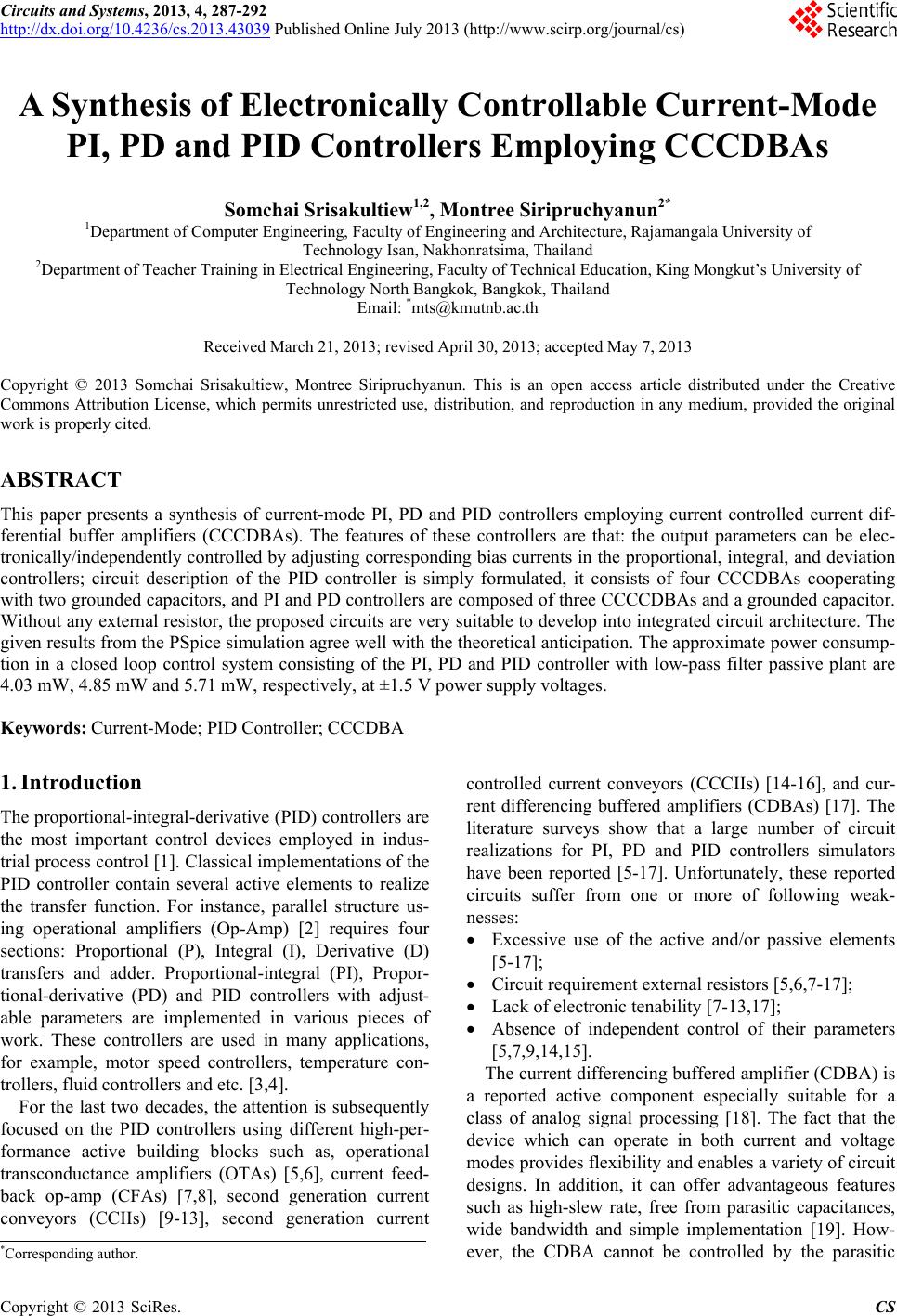
 Circuits and Systems, 2013, 4, 287-292 http://dx.doi.org/10.4236/cs.2013.43039 Published Online July 2013 (http://www.scirp.org/journal/cs) A Synthesis of Electronically Controllable Current-Mode PI, PD and PID Controllers Employing CCCDBAs Somchai Srisakultiew1,2, Montree Siripruchyanun2* 1Department of Computer Engineering, Faculty of Engineering and Architecture, Rajamangala University of Technology Isan, Nakhonratsima, Thailand 2Department of Teacher Training in Electrical Engineering, Faculty of Technical Education, King Mongkut’s University of Technology North Bangkok, Bangkok, Thailand Email: *mts@kmutnb.ac.th Received March 21, 2013; revised April 30, 2013; accepted May 7, 2013 Copyright © 2013 Somchai Srisakultiew, Montree Siripruchyanun. This is an open access article distributed under the Creative Commons Attribution License, which permits unrestricted use, distribution, and reproduction in any medium, provided the original work is properly cited. ABSTRACT This paper presents a synthesis of current-mode PI, PD and PID controllers employing current controlled current dif- ferential buffer amplifiers (CCCDBAs). The features of these controllers are that: the output parameters can be elec- tronically/independently controlled by adjusting corresponding bias currents in the proportional, integral, and deviation controllers; circuit description of the PID controller is simply formulated, it consists of four CCCDBAs cooperating with two grounded capacitors, and PI and PD controllers are composed of three CCCCDBAs and a grounded capacitor. Without any external resistor, the proposed circuits are very suitable to develop into integrated circuit architecture. The given results from the PSpice simulation agree well with the theoretical anticipation. The approximate power consump- tion in a closed loop control system consisting of the PI, PD and PID controller with low-pass filter passive plant are 4.03 mW, 4.85 mW and 5.71 mW, respectively, at ±1.5 V power supply voltages. Keywords: Current-Mode; PID Controller; CCCDBA 1. Introduction The proportional-integral-derivative (PID) controllers are the most important control devices employed in indus- trial process control [1]. Classical implementations of the PID controller contain several active elements to realize the transfer function. For instance, parallel structure us- ing operational amplifiers (Op-Amp) [2] requires four sections: Proportional (P), Integral (I), Derivative (D) transfers and adder. Proportional-integral (PI), Propor- tional-derivative (PD) and PID controllers with adjust- able parameters are implemented in various pieces of work. These controllers are used in many applications, for example, motor speed controllers, temperature con- trollers, fluid controllers and etc. [3,4]. For the last two decades, the attention is subsequently focused on the PID controllers using different high-per- formance active building blocks such as, operational transconductance amplifiers (OTAs) [5,6], current feed- back op-amp (CFAs) [7,8], second generation current conveyors (CCIIs) [9-13], second generation current controlled current conveyors (CCCIIs) [14-16], and cur- rent differencing buffered amplifiers (CDBAs) [17]. The literature surveys show that a large number of circuit realizations for PI, PD and PID controllers simulators have been reported [5-17]. Unfortunately, these reported circuits suffer from one or more of following weak- nesses: Excessive use of the active and/or passive elements [5-17]; Circuit requirement external resistors [5,6,7-17]; Lack of electronic tenability [7-13,17]; Absence of independent control of their parameters [5,7,9,14,15]. The current differencing buffered amplifier (CDBA) is a reported active component especially suitable for a class of analog signal processing [18]. The fact that the device which can operate in both current and voltage modes provides flexibility and enables a variety of circuit designs. In addition, it can offer advantageous features such as high-slew rate, free from parasitic capacitances, wide bandwidth and simple implementation [19]. How- ever, the CDBA cannot be controlled by the parasitic *Corresponding author. C opyright © 2013 SciRes. CS 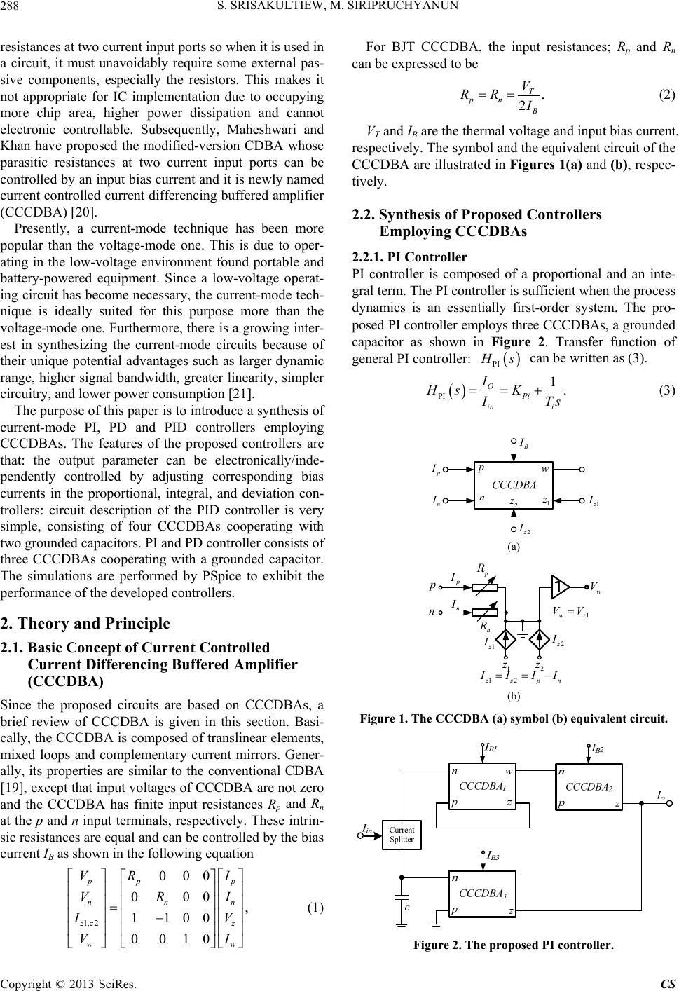 S. SRISAKULTIEW, M. SIRIPRUCHYANUN 288 resistances at two current input ports so when it is used in a circuit, it must unavoidably require some external pas- sive components, especially the resistors. This makes it not appropriate for IC implementation due to occupying more chip area, higher power dissipation and cannot electronic controllable. Subsequently, Maheshwari and Khan have proposed the modified-version CDBA whose parasitic resistances at two current input ports can be controlled by an input bias current and it is newly named current controlled current differencing buffered amplifier (CCCDBA) [20]. Presently, a current-mode technique has been more popular than the voltage-mode one. This is due to oper- ating in the low-voltage environment found portable and battery-powered equipment. Since a low-voltage operat- ing circuit has become necessary, the current-mode tech- nique is ideally suited for this purpose more than the voltage-mode one. Furthermore, there is a growing inter- est in synthesizing the current-mode circuits because of their unique potential advantages such as larger dynamic range, higher signal bandwidth, greater linearity, simpler circuitry, and lower power consumption [21]. The purpose of this paper is to introduce a synthesis of current-mode PI, PD and PID controllers employing CCCDBAs. The features of the proposed controllers are that: the output parameter can be electronically/inde- pendently controlled by adjusting corresponding bias currents in the proportional, integral, and deviation con- trollers: circuit description of the PID controller is very simple, consisting of four CCCDBAs cooperating with two grounded capacitors. PI and PD controller consists of three CCCDBAs cooperating with a grounded capacitor. The simulations are performed by PSpice to exhibit the performance of the developed controllers. 2. Theory and Principle 2.1. Basic Concept of Current Controlled Current Differencing Buffered Amplifier (CCCDBA) Since the proposed circuits are based on CCCDBAs, a brief review of CCCDBA is given in this section. Basi- cally, the CCCDBA is composed of translinear elements, mixed loops and complementary current mirrors. Gener- ally, its properties are similar to the conventional CDBA [19], except that input voltages of CCCDBA are not zero and the CCCDBA has finite input resistances Rp and Rn at the p and n input terminals, respectively. These intrin- sic resistances are equal and can be controlled by the bias current IB as shown in the following equation 1, 211 00 p n zz R R For BJT CCCDBA, the input resistances; Rp and Rn can be expressed to be 000 000 , 00 10 pp nn z ww VI VI IV VI (1) . 2 T pn V RR (2) VT and IB are the thermal voltage and input bias current, respectively. The symbol and the equivalent circuit of the CCCDBA are illustrated in Figures 1(a) and (b), respec- tively. 2.2. Synthesis of Proposed Controllers Employing CCCDBAs 2.2.1. P I C ontroller PI controller is composed of a proportional and an inte- gral term. The PI controller is sufficient when the process dynamics is an essentially first-order system. The pro- posed PI controller employs three CCCDBAs, a grounded capacitor as shown in Figure 2. Transfer function of general PI controller: PI s can be written as (3). PI 1 OPi in i I HsK . Ts (3) n w 1 z 2 z p 1 n 2 (a) p R n n n w V 12 1wz VV 1 2 zpn III 1 z 2 z (b) Figure 1. The CCCDBA (a) symbol (b) equivalent circuit. Figure 2. The proposed PI controller. Copyright © 2013 SciRes. CS 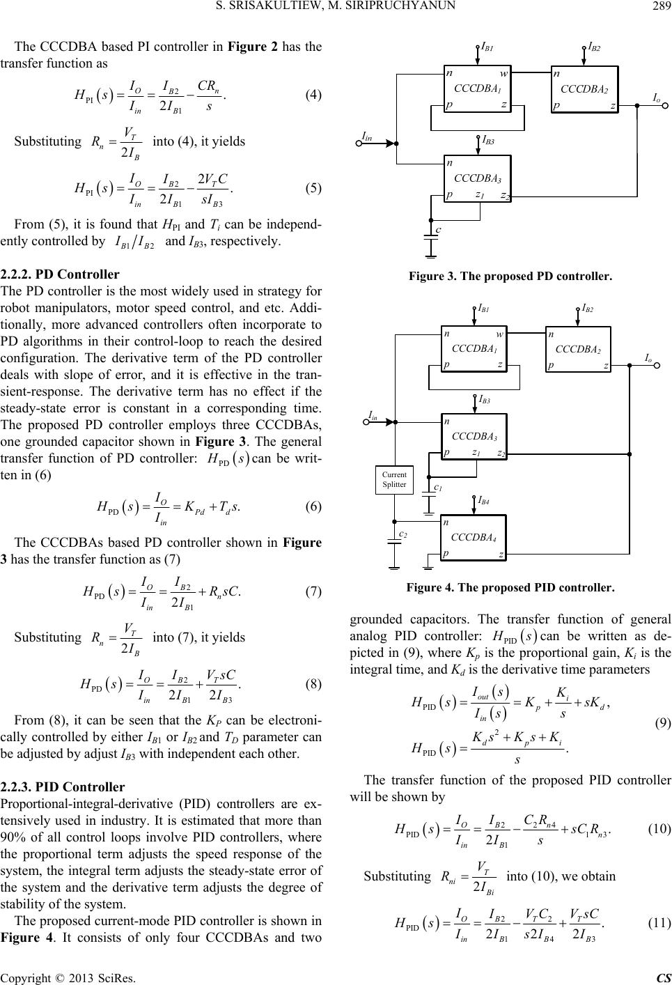 S. SRISAKULTIEW, M. SIRIPRUCHYANUN 289 The CC 2 has the tra CDBA based PI controller in Figure nsfer function as 2 1 . 2 On B B PI in CR I Hs Is (4) g Substitutin 2 T n V R into (4), it yields PI O in I2 13 2. 2 BT B B VC IIsI (5) From (5), it is found that HPI and T can be independ- en Hs i tly controlled by 12 B I and IB3, respectively. Figure 3. The proposed PD controller. 2.2.2. PD Controller e most widely used in strategy for The PD controller is th robot manipulators, motor speed control, and etc. Addi- tionally, more advanced controllers often incorporate to PD algorithms in their control-loop to reach the desired configuration. The derivative term of the PD controller deals with slope of error, and it is effective in the tran- sient-response. The derivative term has no effect if the steady-state error is constant in a corresponding time. The proposed PD controller employs three CCCDBAs, one grounded capacitor shown in Figure 3. The general transfer function of PD controller: PD scan be writ- ten in (6) PD O in I. Pd d sKTs (6) The CCCDBAs based PD controller shown in Figure 3 I has the transfer function as (7) 2 1 . 2 Bn B PD O in II sRsC II (7) g Substitutin2 T n V R into (7), it yields 2 13 . 22 BT B B PD O in I VsC Hs II (8) From (8), it can be seen that the KP can be electroni- ca 2.2.3. PID Controlle r rivative (PID) controllers are ex- mode PID controller is shown in Fi lly controlled by either IB1 or IB2 and TD parameter can be adjusted by adjust IB3 with independent each other. Proportional-integral-de tensively used in industry. It is estimated that more than 90% of all control loops involve PID controllers, where the proportional term adjusts the speed response of the system, the integral term adjusts the steady-state error of the system and the derivative term adjusts the degree of stability of the system. The proposed current- gure 4. It consists of only four CCCDBAs and two p n z CCCDBA1 IB3 p n z2 CCCDBA3 Iin c1 IB1 IB2 p n z CCCDBA2 w Io z1 IB4 p n z CCCDBA4 Current Splitter c2 Figure 4. The proposed PID controller. rounded capacitors. The transfer function of general g analog PID controller: PID scan be written as de- picted in (9), where Kp isportional gain, Ki is the integral time, and Kd is the derivative time parameters the pro PID 2 PID , . out i d in dpi Is K sKsK Is s KsKs K Hs s (9) The transfer function of the proposed PID controller w ill be shown by 24 2 PID1 3 1 . 2 On Bn in B ICR I ssCR II s (10) Substituting 2 T ni i V R into (10), we obtain 22 PID 143 . 222 OBTT in BBB I VC VsC Hs IsI I (11) Copyright © 2013 SciRes. CS 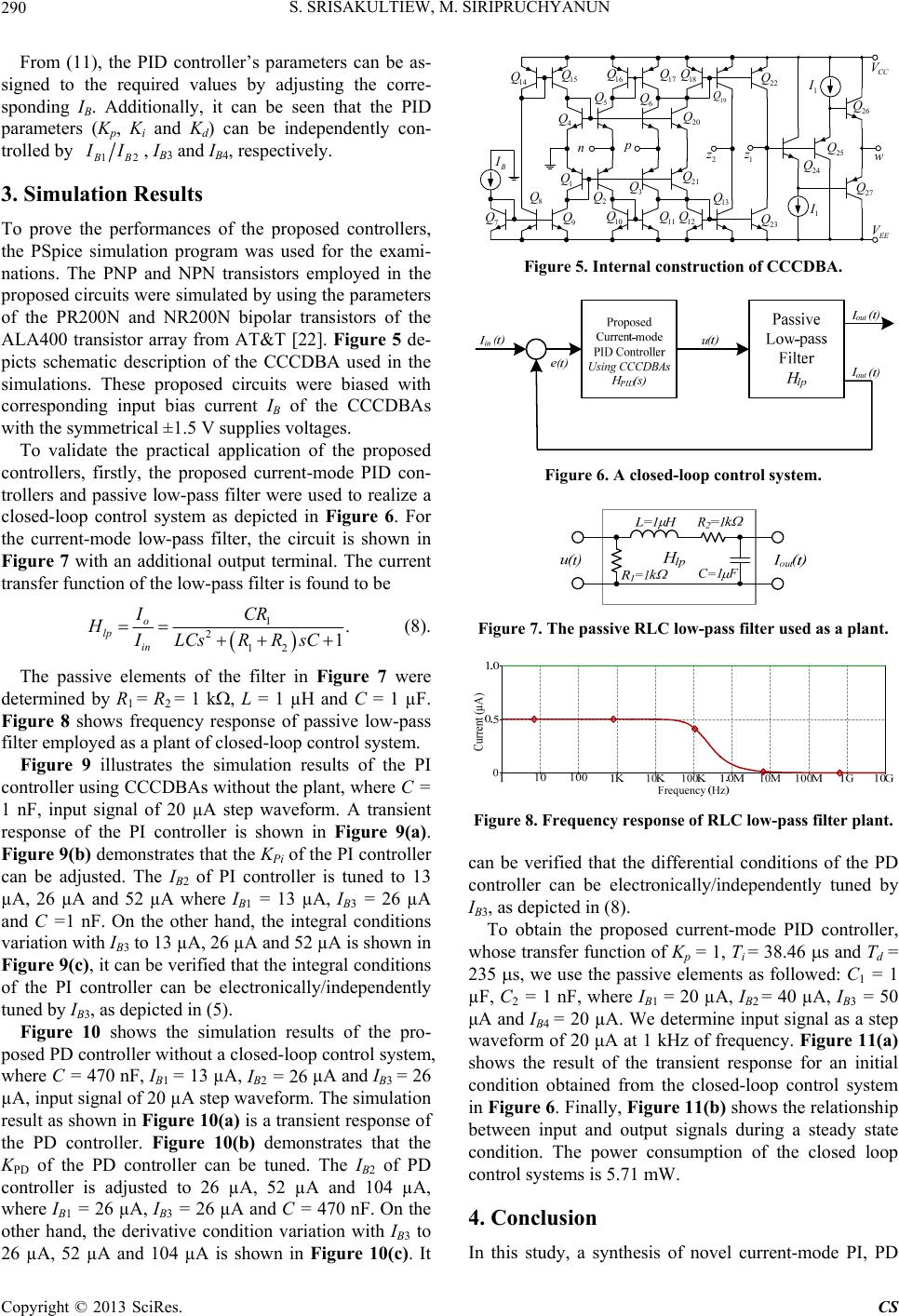 S. SRISAKULTIEW, M. SIRIPRUCHYANUN 290 From (11), the PID controller’s parameters can be signed to the required values by adjusting sponding I. Additionally, it can be seen that the PID pa as- the corre- B rameters (Kp, K i and Kd) can be independently con- trolled by 12 B I, IB3 and IB4, respectively. 3. Simulation Results To prove rmances of the proposed the perfocontrollers, am was used for the exami- transistors employed in the realize a cl the PSpice simulation progr nations. The PNP and NPN proposed circuits were simulated by using the parameters of the PR200N and NR200N bipolar transistors of the ALA400 transistor array from AT&T [22]. Figure 5 de- picts schematic description of the CCCDBA used in the simulations. These proposed circuits were biased with corresponding input bias current IB of the CCCDBAs with the symmetrical ±1.5 V supplies voltages. To validate the practical application of the proposed controllers, firstly, the proposed current-mode PID con- trollers and passive low-pass filter were used to osed-loop control system as depicted in Figure 6. For the current-mode low-pass filter, the circuit is shown in Figure 7 with an additional output terminal. The current transfer function of the low-pass filter is found to be 1 2 12 . 1 o lp in ICR HILCsRRsC (8). The passive elements of the filter in Figure 7 determined by R1 = R2 = 1 k, L = 1 µH and Figure 8 shows frequency response of passive low-pass fil re I = 26 µA and I= 26 µA were C = 1 µF. ter employed as a plant of closed-loop control system. Figure 9 illustrates the simulation results of the PI controller using CCCDBAs without the plant, where C = 1 nF, input signal of 20 µA step waveform. A transient sponse of the PI controller is shown in Figure 9(a). Figure 9(b) demonstrates that the KPi of the PI controller can be adjusted. The IB2 of PI controller is tuned to 13 µA, 26 µA and 52 µA where IB1 = 13 µA, IB3 = 26 µA and C =1 nF. On the other hand, the integral conditions variation with IB3 to 13 µA, 26 µA and 52 µA is shown in Figure 9(c), it can be verified that the integral conditions of the PI controller can be electronically/independently tuned by IB3, as depicted in (5). Figure 10 shows the simulation results of the pro- posed PD controller without a closed-loop control system, where C = 470 nF, IB1 = 13 µA, B2B3 , input signal of 20 µA step waveform. The simulation result as shown in Figure 10( a) is a transient response of the PD controller. Figure 10(b) demonstrates that the KPD of the PD controller can be tuned. The IB2 of PD controller is adjusted to 26 µA, 52 µA and 104 µA, where IB1 = 26 µA, IB3 = 26 µA and C = 470 nF. On the other hand, the derivative condition variation with IB3 to 26 µA, 52 µA and 104 µA is shown in Figure 10(c). It 1 Q 2 Q 3 Q 21 Q 4 7 Q 8 Q 9 Q 10 Q 11 Q 12 Q 13 Q Q 5 Q 6 Q 20 Q 14 Q 15 Q16 Q17 Q 18 Q 19 Q n 2 z 23 Q CC V E V 1 z 24 Q 1 1 25 Q 27 Q w Figure 5. Internal construction of CCCDBA. 26 Q 22 Q Figure 6. A closed-loop control system. Figure 7. The passive RLC low-pass filter used as a plant. Figure 8. Frequency response of RLC low-pass filter plant. can be verified that the differential conditions of the PD 3, as depicted in (8). e elements as followed: C1 = 1 µF novel current-mode PI, PD controller can be electronically/independently tuned by IB To obtain the proposed current-mode PID controller, whose transfer function of Kp = 1, Ti = 38.46 s and Td = 235 s, we use the passiv , C2 = 1 nF, where IB1 = 20 µA, IB2 = 40 µA, IB3 = 50 μA and IB4 = 20 µA. We determine input signal as a step waveform of 20 μA at 1 kHz of frequency. Figure 11(a) shows the result of the transient response for an initial condition obtained from the closed-loop control system in Figure 6. Finally, Figure 11(b) shows the relationship between input and output signals during a steady state condition. The power consumption of the closed loop control systems is 5.71 mW. 4. Conclusion In this study, a synthesis of Copyright © 2013 SciRes. CS  S. SRISAKULTIEW, M. SIRIPRUCHYANUN 291 (a) (b) (c) Figure 9. Simulation results of proposed PI controller. (a) (b) (c) (a) Figure 11. Input and output relationship of PID controller with closed-loop control system. and PID controllers were realized by employing CCCDBAs. All PI, PD and PID parameters can be tuned electroni- cally and independently by the corresponding bias cur- rents. The circuit description of the PID controller com- prises only four CCCDBAs and two grounded capacitors. PI and PD controller consisf three CCCDBAs coop erating with a grounded capacitor, without any external n control systems using a pensation for Current Mode Step-Down Converters,” Ap. Note SLVA350. http://focus.ti.2.pdf anwisut and M. Siripruchyanun, (b) ts o- resistor. Simulation results confirm the theoretical analy- sis. It is easily modified to use i microcontroller [20]. With mentioned features, it is very suitable to realize the proposed controllers in a mono- lithic chip for use in battery-powered electronic devices. REFERENCES [1] A. J. Michael and H. M. Mohammad, “PID Control New Identification and Design Methods,” Springer, Berlin, 2005. [2] S. Franco, “Design with Operational Amplifiers and Ana- log Integrated Circuits,” McGraw-Hill, New York, 1997. [3] B. C. Kuo, “Automatic Control System,” Prentice-Hall, Up- per Saddle River, 1997. [4] “Designing Ultrafast Loop Response with Type-III Com- 2, Texas Instrument, 201 com/lit/an/slva352/slva35 [5] C. Edral, A. Toker and C. Acar, “OTA-C Based Propor- tional-Integral-Derivative (PID) Controller and Calculat- ing Optimum Parameter Tolerances,” Turkish Journal of Electrical Engineering and Computer Sciences, Vol. 9, No. 2, 2001, pp. 189-198. [6] S. Srisakultiew, S. Law “A Synthesis of Electronically Controllable Current-Mode PI, PD and PID Controllers Employing OTAs,” The Pro- Figure 10. Simulation results of proposed PD controller. Copyright © 2013 SciRes. CS  S. SRISAKULTIEW, M. SIRIPRUCHYANUN Copyright © 2013 SciRes. CS 292 4-15 May 2012. iers (CFAs) ceeding of 10th International Prince of Songkla University (PSU) Engineering Conference, Songkhla, 1 [7] E. Cevat, “A New Current-Feedback-Amplif Based Proportional-Integral-Derivative (PID) Controller Realization and Calculating Optimum Parameter Toler- ances,” Pakistan Journal of Applied Sciences, Vol. 2, No. 1, 2002, pp. 56-59. doi:10.3923/jas.2002.56.59 [8] S. Srisakultiew, S. Lawanwisut and M. Siripruchyanun, por , “Current Conveyors, Operational Ampli- ng of the IEEE Interna- Proceeding of Electrical Engineering Kuntman and S. Kafali, “A Current Con- CCCII,” Proceed- The Pro- ional Journal of Engineering “A Synthesis of Current-Mode PI, PD and PID Control- lers Employing CFAs,” The Proceeding of 51th Kasetsart University Annual Conference, Bangkok, February 2013, pp. 144-151. [9] S. Minaei, E. Yuce, S. Tokat and O. Cicekoglu, “Simple Realization of Current-Mode and Voltage-Mode PID, PI and PD Controllers,” Proceedings of the IEEE Interna- tional Symposium on Industrial Electronics, Dubrovnik, 20-23 June 2005, pp. 195-198. [10] E. Cevat, A. Toker and C. Acar, “A New Protional- Integral-Derivative (PID) Controller Realization by Using Current Conveyor and Calculating Optimum Parameter Tolerances,” Journal of Electrical and Electronics, Vol. 1, 2001, pp. 267-273. [11] J. A. Svoboda fiers and Nullors,” IEE Proceedings, Vol. 136, No. 6, 1989, pp. 317-322. [12] S. Minaei, E. Yuce, S. Takat and O. Cicekoglu, “Simple Realizations of Current-Mode and Voltage-Mode PID, PI and PD Controller,” Proceedi tional Symposium on Industrial Electronics, Vol. 1, 2005, pp. 195-198. [13] V. Srikul, S. Srisakultiew and M. Siripruchyanun, “A Synthesis of Current-Mode PI, PD and PID Controllers Employing CCIIs,” Network 2012 of Rajamangala University of Technology, Nong Khai, April 2012, pp. 513-516. [14] C. Erdal, H. trolled Conveyor Based Proportional-Integral-Derivative (PID) Controller,” Journal of Electrical & Electronics En- gineering, Vol. 4, No. 2, 2004, pp. 1248-1248. [15] W. Naksup, V. Kiranon, J. Vongdektum and V. Sangpisit, “PID, PI and PD Controllers Based on ing of 31st Electrical Engineering Conference, Nakhon- nayok, 2009, pp. 927-930. [16] S. Srisakultiew and M. Siripruchyanun, “A Synthesis of Current-Mode PID Controller Using CCCIIs,” ceeding of 3rd National Conference on Technical Educa- tion, 2010, pp. 63-68. [17] A. U. Keskin, “Design of a PID Controller Circuit Em- ploying CDBAs,” Internat Education, Vol. 43, No.1, 2006, pp. 48-56. doi:10.7227/IJEEE.43.1.5 [18] C. Acar and S. Ozoguz, “A New Versatile Building Block: Current Differ-Encing B uffered Amplifier Suitable for Ana- log Signal Processing Filters,” Microelectronics Journal, Vol. 30, No. 2, 1999, pp. 157-160. doi:10.1016/S0026-2692(98)00102-5 [19] S. Ozoguz, A. Toker and C. Acar, “Current-Mode Continu- ous-Time Fully-Integrated Universal Filter Using CDBAs,” Electronics Letters, Vol. 35, No. 2, 1999, pp. 97-98. doi:10.1049/el:19990118 [20] S. Maheshwari and I. A. Khan, “Curr rent Differencing Buffered Amplifier: ent-Controlled Cur- Implementation and Applications,” Active and Passive Electronic Components, Vol. 27, No. 4, 2004, pp. 219-227. doi:10.1080/08827510310001648924 [21] C. Toumazou, F. J. Lidgey and D. G. Haigh, “Analog IC ircuit Devices -416. Design: The Current Approach,” Peter Peregrinus, Lon- don, 1990. [22] D. R. Frey, “Log-Domain Filtering: An Approach to Cur- rent-Mode Filtering,” IEE Proceeding C System, Vol. 140, No. 6, 1993, pp. 406
|