Circuits and Systems, 2013, 4, 280-286
http://dx.doi.org/10.4236/cs.2013.43038 Published Online July 2013 (http://www.scirp.org/journal/cs)
An Active-Only Temperature-Insensitive Current-Mode
Biquad Filter Based on Differentiator Structures
Employing CCCCTAs
Supawat Lawanwisut1, Montree Siripruchyanun1*, Winai Jaikla2
1Department of Teacher Training in Electrical Engineering, Faculty of Technical Education,
King Mongkut’s University of Technology North Bangkok, Bangkok, Thailand
2Department of Engineering Education, Faculty of Industrial Education, King Mongkut’s
Institute of Technology Ladkrabang, Bangkok, Thailand
Email: *mts@kmutnb.ac.th
Received February 14, 2013; revised March 15, 2013; accepted March 25, 2013
Copyright © 2013 Supawat Lawanwisut et al. This is an open access article distributed under the Creative Commons Attribution
License, which permits unrestricted use, distribution, and reproduction in any medium, provided the original work is properly cited.
ABSTRACT
This article presents an active-only current-mode universal biquad filter performing three standard functions: low-pass,
high-pass and band-pass function, which can be readily modified to achieve the rest functions (band-stop and all-pass).
The circuit principle is based on active-only circuit designed by using differentiators which are constructed from current
controlled current conveyor transconductance amplifier (CCCCTA) cooperating with an internally frequency compen-
sated operational amplifier (OA). The features of the circuit are that: the pole frequency and quality factor can be inde-
pendently tuned via the input bias currents and it is ideally temperature-insensitive, its circuit description is very simple,
consisting of 3 CCCCTAs and 2 operational amplifiers, and the proposed circuit is very appropriate for further devel-
oping into integrated circuit architecture. The PSpice simulation results are shown. The given results agree well with the
theoretical anticipation.
Keywords: Active-Only; CCCCTA; Current-Mode; Biquad Filter
1. Introduction
An analog filter is an important building block, widely
used for continuous-time signal processing. It can be
found in many fields: including, communications, meas-
urement, instrumentation, and control systems [1,2]. One
of the most popular analog filters is a universal biquad
filter, since it can simultaneously provide several func-
tions in the same circuit topology. Recently, a universal
filter working in current-mode has been more popular
than the voltage-mode type. Since last two decades, there
has been much effort to reduce the supply voltage of
analog systems. This is due to the demand for portable
and battery-powered equipment. Since a low-voltage
operating circuit becomes necessary, the current-mode
technique is ideally suited for this purpose. Actually, a
circuit using the current-mode technique has many other
advantages, such as, larger dynamic range, higher band-
width, greater linearity, simpler circuitry and lower power
consumption [3,4].
The synthesis and design of analog signal processing
circuits using only active elements without passive ele-
ments are important in fully integrated circuit (IC) tech-
nology. This technique makes circuit become smaller
chip area, lower power consumption, wider frequency
range of operation and programmability [5-8], where the
applications can be easily seen in many literatures, for
example filter [7], oscillator [9], inductance simulator [10]
and etc.
From the past, creation of differentiator circuit must
use an inductor worked together with an active element
which affected on circuit as large sized. So, it was not
popular to create circuit with differentiator. But nowa-
days, we can design differentiator-based circuit without
any inductor, and then causing a reduction in circuit
sized smaller than creation circuit in the past. Biquadratic
transfer function is widely used in order to synthesize the
filters. Many kinds of filters can be realized based on
only integrators as building blocks [11-14]. However,
*Corresponding author.
C
opyright © 2013 SciRes. CS
S. LAWANWISUT ET AL. 281
integrator circuit performs as a low-pass filter. At high
frequency, stage-gain of integrator is decayed due to
components bandwidth and integrator characteristic. In
order to realize filter, magnitude response of filter in
high-frequency would be unstable according to the men-
tioned characteristics. Differentiator circuit can perform
as a high-pass filter that compensated with component
bandwidth for stabilization of magnitude response in
high-frequency [15].
A reported 5-terminals active element, namely current
convey transconductance amplifier (CCTA) [16] has
been proposed in 2005, it seems to be a versatile compo-
nent in the realization of a class of analog signal proc-
essing circuits, especially analog frequency filters. It is a
really current-mode element whose input and output sig-
nals are currents. In addition, the output current gain can
be adjusted via input bias current. However, the parasitic
resistance at current input port of the CCTA cannot be
controlled. Recently, Siripruchyanun and Jaikla have
proposed the modified-version CCTA, whose parasitic
resistance at current input port can be controlled by an
input bias current. It is newly named current controlled
current conveyor transconductance amplifier (CCCCTA)
[17]. It seems to be a useful building block, since many
circuits and systems can be implemented by employing
only single CCCCTA. Presently, the CCCCTA has been
extensively used, such as filters [18,19], oscillators [20,
21], inductance simulators [22], and etc.
From our recent survey, it is found that several im-
plementations of current-mode universal biquad filters
using active-only principle have been reported. Unfortu-
nately, these reported circuits suffer from one or more of
following weaknesses:
Excessive use of the active elements [23,24].
Lack of electronic adjustability [23,24].
The pole frequency and quality factor cannot be in-
dependently tuned [18,25].
The aim of this paper is to propose a new current-
mode universal biquad filter. The features of proposed
circuit are that: it employs 3 CCCCTAs and 2 internally
frequency compensated operational amplifiers; the pro-
posed universal biquad filter can provide 3 standard
functions including low-pass, high-pass and band-pass
functions in the same time without changing circuit to-
pology, where the rest functions (band-stop and all-pass)
can be readily obtained by small modification; the circuit
description is very simple, which results in a small-size
of the monolithic chip. In addition, it is electronically
tunable and convenient to use. The quality factor and
pole frequency can be electronically and independently
adjusted. The PSpice simulation results are also shown,
which are in correspondence with the theoretical analy-
sis.
2. Theory and Principle
2.1. Implementation Topology of the Proposed
Filter
The filter is designed by cascading current adder and the
current-mode lossless differentiators fed-back by current
amplifier whose gain of k as systematically shown in
Figure 1. From block diagram in Figure 1, its transfer
function can be found to be
2
1
,
1
LP
in
Iab
sk
Isbab

(1)
2
,
1
BP
in
s
Ib
sk
Isbab

(2)
and
2
21
HP
in
Is
sk
Isbab

. (3)
0
From Equations (1)-(3), the pole frequency
and
quality factor
0
Q can be respectively expressed as
0
1,
ab
(4)
and
1.
b
Qka
(5)
It is found that the pole frequency can be adjusted by
either a or b, by keeping their ratio to be constant where
the quality factor can be tuned through k without effect-
ing the pole frequency.
2.2. Basic Concept of CCCCTA
The principle of the CCCCTA was firstly published in
2008 by Siripruchyanun and Jaikla [17]. The schematic
symbol and the ideal behavioral model of the CCCCTA
are shown in Figures 2(a) and (b), respectively. The
characteristics of the ideal CCCCTA are represented by
Figure 1. Block diagram for proposed filter implementa-
tion.
Copyright © 2013 SciRes. CS
S. LAWANWISUT ET AL.
282
the following equation:
,
00
10
00
c
y0 0
100
0 0
0
x
x
x
y
zz
z
mo
o
I
I
V
I
RV
V
g
V







I







(6)
If the CCCCTA is realized using a BJT technology,
x
Rm
and
can be respectively written as
1
,
2
T
xB
V
R
I
(7)
and
2,
2
B
mT
I
gV
(8)
where m
is transconductance of the CCCCTA. T is
the thermal voltage equal to 26 mV at a room tempera-
ture. 1
V
B
I
and 2
B
I
are the bias currents used to control
the parasitic resistance and transconductance of the
CCCCTA. In general, CCCCTA can contain an arbitrary
number of o terminals, providing currents IO of both di-
rections, respectively. A possible BJT implementation of
the CCCCTA is shown in Figure 3.
2.3. Internally Frequency Compensated
Operational Amplifier
The open-loop gain of a practical internally frequency
1B
I
y
x
z
o
CCCCTA
y
i
x
i
z
i
o
i
2B
I
y
V
x
V
z
V
o
V
(a)
1
y
x
o
x
i
x
i
mZ
gV
x
R
z
(b)
Figure 2. CCCCTA (a) Symbol (b) Equivalent circuit.
1B
I
1
Q
2
Q
3
Q
4
Q
5
Q
6
Q
7
Q
8
Q
9
Q
17
Q
18
Q
19
Q
20
Q
22
Q
2B
I
z
x
o
11
Q
16
Q
CC
V
EE
V
21
Q
23
Q
15
Q
10
Q
24
Q
12
Q
o
14
Q
26
Q
27
Q
13
Q
y
25
Q
Figure 3. Schematic of the BJT CCCCTA.
compensated operational amplifier is represented
by the following transfer function

OA

01
11
,
p
pp
AB
As ss



(9)
where Ao is open-loop DC gain, 1
p
is the first pole
frequency and
BA
1
1op is the gain-bandwidth pro-
duct of the operational amplifier. For the frequencies
p
, Equation (9) is approximately given by [5,7]

.
B
As
s
,
OutA inA
(10)
3. Proposed Current-Mode Biquad Filter
As mentioned in last section, the proposed filter is based
on current amplifier and the current-mode lossless dif-
ferentiators. In this section, these circuits will be de-
scribed. The current amplifier based on the CCCCTA is
shown in Figure 4. The output current of this circuit can
be written to be
I
kI (11)
where 2
mx . Figure 5 shows the lossless differ-
entiator using the CCCCTA. Considering the circuit in
Figure 5 and using the CCCCTA properties, we will
receive
kgR
,
OutB
inB
I
s
a
I (12)
where
x
m
Rg
aB
.
1
B
I
2
B
I
OutA
I
inA
I
Figure 4. Current amplifier based on CCCCTA.
3
B
I
4
B
I
OutB
I
inB
I
Figure 5. Lossless differentiator using CCCCTA and OA.
Copyright © 2013 SciRes. CS
S. LAWANWISUT ET AL. 283
The completed current-mode biquad filter is shown in
Figure 6, based on filter topology in Figure 1. From
Equation (12), if 12 for easy consideration,
the output current transfer functions of the circuit at each
output terminal in Figure 6 can be obtained as
0
12 1 2
1,
xxmm
BRRg g
BBB
2
12 1 2
233
22
2
Lp xxmm
in xm
xm
B
IRRg g
IRg
ss Rg R




2
1212
,
xxmm
BB
Rgg
 
 
 
(13)
22
233
22
2
Bp xm
in xm
xm
sB
IRg
IRg
ss Rg R




2
1212
,
xxmm
BB
Rgg
 
 
 
(14)
2
233
22
2
Hp
in xm
xm
Is
IRg
ss Rg R




2
1212
,
xxmm
BB
Rgg
 
 
 
(15)
Moreover, the band-stop and the all-pass functions can
be further obtained, combining the currents
BS
I
H
PLP
I
I and 
APBS BP
I
II, respectively, where
2
2
12 1
233
22
2
BSxxm m
in xm
xm
B
s
IR
IRg
ss Rg R




2
2
1212
,
xxmm
Rgg
BB
Rgg
 
 
 
(16)
2
12
2
1212
.
mm
xxmm
sB B
g
BB
Rgg
 
 
 
2
22 12
233
22
2
xm xx
AP
in xm
xm
sRg RRg
I
IRg
ss Rg R





(17)
The pole frequency
0
and quality factor
0
Q
can be respectively expressed to be
3
B
I
4
B
I
1
B
I
2
B
I
B
P
I
L
P
I
5
B
I
6
B
I
I
n
I
CCCCTA1
x
x
x
o
yy
y
z
z
o
o
z
o
o
CC
CCCCTA3
CCTA2
HP
I
o
1
()
A
S
2
()
A
S
Figure 6. Completely proposed current-mode biquad filter.
(18)
and
22
11
1.
xm
xm
Rg
QkRg
(19)
Substituting Rx1 = 1B
VI Rx2 = 2,
T3
VI Rx2 = 2,
TB
5
2,
TB
VI gm1 = 22,
B
T
V gm2 = 4
I
I
2
B
T
V and g
m3 =
6
I
2,
B
T
Vthe pole frequency and quality factor can be
rewritten to be
13
0
24
4,
BB
BB
I
I
B (20)
I
I
and
514
623
8.
BBB
BBB
I
I
I
Q (21)
I
II
It is obviously found that, from Equations (20) and
(21), the pole frequency can be adjusted independently
from the quality factor by varying either 1
B
I
and 3
B
I
or 2
B
I
and 4
B
I
(keeping their ratio to be constant),
where the quality factor can be adjusted by 5
B
I
or 6
B
I
without affecting the pole frequency. In addition, if the
gain-bandwidth product
B is independent of tem-
perature variation, it is seen that the pole frequency and
quality factor are ideally temperature insensitive.
4. Sensitivity Analysis
The sensitivities of the proposed circuit can be found as
00 0
13 24
,,
11
,,1,
22
BBB B
II IIB
SS S
 
(22)
 
and
00 00
5614 23
,,,
11
1, 1,,
22
BBBBBB
QQQ Q
BIII III
SSS S (23)
 
13
30 μA, 400μA
Therefore, all active and passive sensitivities are equal
or less than unity in magnitude.
5. Simulation Results
The working performances of the proposed biquad filter
were verified in PSpice simulation using the BJT imple-
mentation of the CCCCTA as shown in Figure 3. The
PNP and NPN transistors employed in the proposed cir-
cuit were simulated by using the parameters of the
PR200N and NR200N bipolar transistors of ALA400
transistor array from AT&T [26]. The OA was simu-
lated by using the parameter of TL082 with the
gain-bandwidth product of B = 4 MHz is used. The cir-
cuit was biased with ±5 V power supplies voltage,
2 4

BB
II II50 μAI
6100 μA,
B B,5B and
B
Iusing ideal current summing circuit. The
Copyright © 2013 SciRes. CS
S. LAWANWISUT ET AL.
284
results shown in Figure 7 are the gain responses of the
proposed biquad filter. It is clearly seen that it can pro-
vide low-pass, high-pass, band-pass functions without
modifying any circuit topology. Figure 8 displays gain
response for band-stop function as depicted in Equation
(16). Figure 9 displays gain and phase responses for
all-pass function analyzed in Equation (17).
Figure 10 displays gain responses of band-pass func-
tion, where 1
B
I
and 3
B
I
are equally set to keep its
ratio to be constant and changed for several values. Fig-
ure 11 shows gain responses of band-pass function,
where 2
B
I
and 4
B
I
are equally set to keep the ratio to
be constant and changed for several values. Figures 12
and 13 are gain responses of band-pass function for dif-
ferent 5
B
I
and 6
B
I
values, respectively. It is shown
that the bandwidth of the responses can be electronically
adjusted by the input bias current 5
B
I
and 6
B
I
without
affecting the pole frequency. Figure 14 shows gain re-
Figure 7. Gain responses of the proposed circuit.
Figure 8. Gain response of the IBS.
Gain(dB)
Phase(d)
Figure 9. Gain and phase responses of the IAP.
Figure 10. Band-pass responses for different values of IB1
and IB3 with keeping its ratio to be c onstant as IB1 = IB3 = IB.
Figure 11. Band-pass responses for different values of IB2
and IB4 with keeping its ratio to be c onstant as IB2 = IB4 = IB.
Figure 12. Band-pass responses for different values of IB5.
Figure 13. Band-pass responses for different values of IB6.
sponses of the band-pass function relative to different
temperatures of 27˚C, 50˚C and 100˚C. From this result,
it can be measured that the average deviation of parame-
ters 0
and due to these temperature variations is
0
Q
Copyright © 2013 SciRes. CS
S. LAWANWISUT ET AL. 285
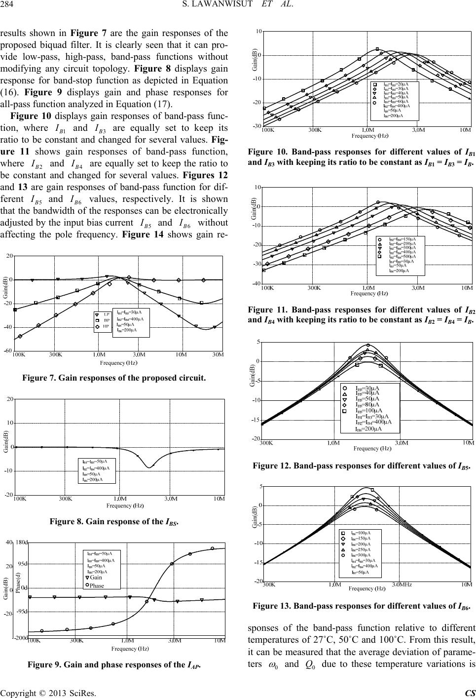
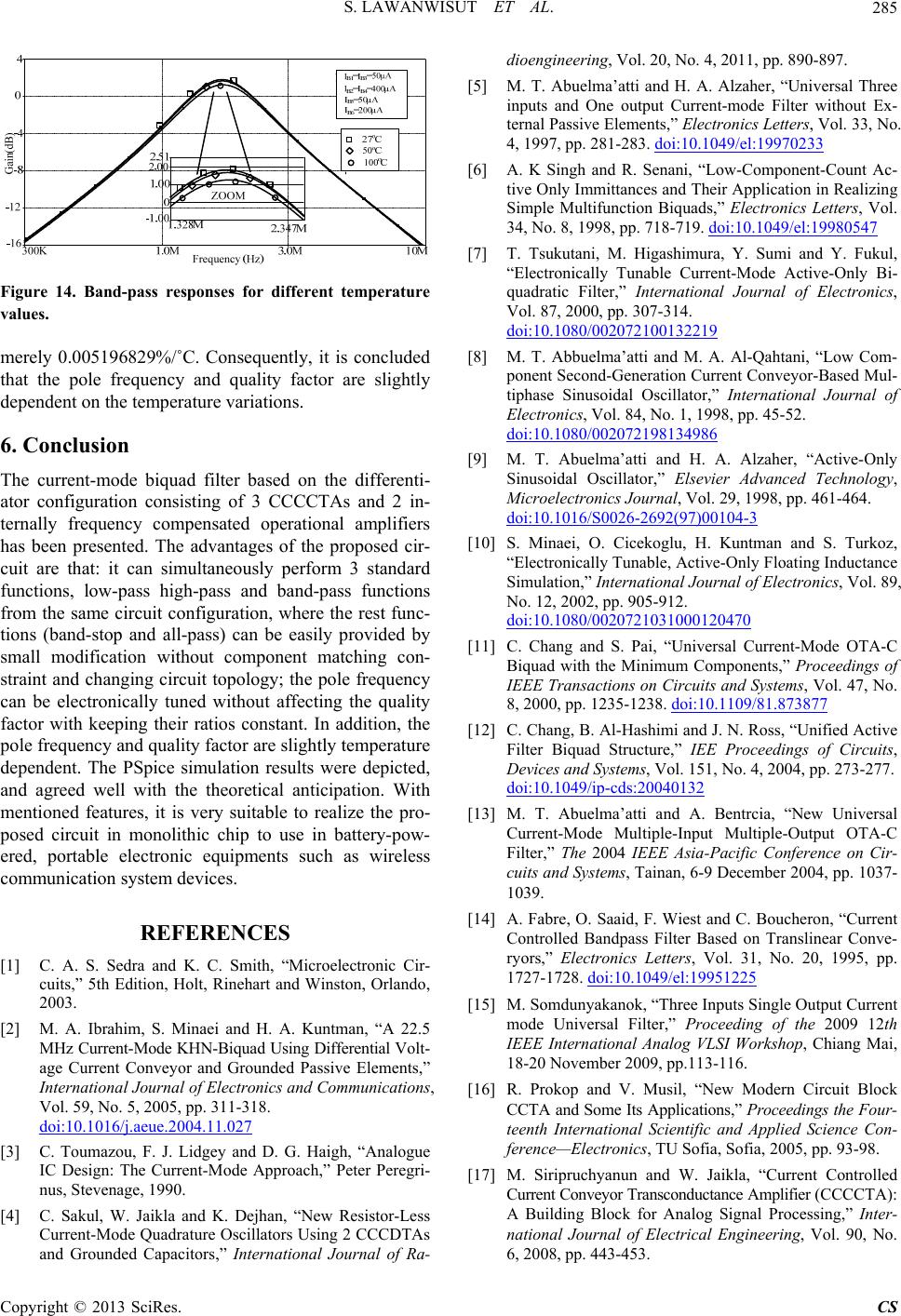
Figure 14. Band-pass responses for different temperature
values.
merely 0.005196829%/˚C. Consequently, it is concluded
that the pole frequency and quality factor are slightly
dependent on the temperature variations.
6. Conclusion
The current-mode biquad filter based on the differenti-
ator configuration consisting of 3 CCCCTAs and 2 in-
ternally frequency compensated operational amplifiers
has been presented. The advantages of the proposed cir-
cuit are that: it can simultaneously perform 3 standard
functions, low-pass high-pass and band-pass functions
from the same circuit configuration, where the rest func-
tions (band-stop and all-pass) can be easily provided by
small modification without component matching con-
straint and changing circuit topology; the pole frequency
can be electronically tuned without affecting the quality
factor with keeping their ratios constant. In addition, the
pole frequency and quality factor are slightly temperature
dependent. The PSpice simulation results were depicted,
and agreed well with the theoretical anticipation. With
mentioned features, it is very suitable to realize the pro-
posed circuit in monolithic chip to use in battery-pow-
ered, portable electronic equipments such as wireless
communication system devices.
REFERENCES
[1] C. A. S. Sedra and K. C. Smith, “Microelectronic Cir-
cuits,” 5th Edition, Holt, Rinehart and Winston, Orlando,
2003.
[2] M. A. Ibrahim, S. Minaei and H. A. Kuntman, “A 22.5
MHz Current-Mode KHN-Biquad Using Differential Volt-
age Current Conveyor and Grounded Passive Elements,”
International Journal of Electronics and Communications,
Vol. 59, No. 5, 2005, pp. 311-318.
doi:10.1016/j.aeue.2004.11.027
[3] C. Toumazou, F. J. Lidgey and D. G. Haigh, “Analogue
IC Design: The Current-Mode Approach,” Peter Peregri-
nus, Stevenage, 1990.
[4] C. Sakul, W. Jaikla and K. Dejhan, “New Resistor-Less
Current-Mode Quadrature Oscillators Using 2 CCCDTAs
and Grounded Capacitors,” International Journal of Ra-
dioengineering, Vol. 20, No. 4, 2011, pp. 890-897.
[5] M. T. Abuelma’atti and H. A. Alzaher, “Universal Three
inputs and One output Current-mode Filter without Ex-
ternal Passive Elements,” Electronics Letters, Vol. 33, No.
4, 1997, pp. 281-283. doi:10.1049/el:19970233
[6] A. K Singh and R. Senani, “Low-Component-Count Ac-
tive Only Immittances and Their Application in Realizing
Simple Multifunction Biquads,” Electronics Letters, Vol.
34, No. 8, 1998, pp. 718-719. doi:10.1049/el:19980547
[7] T. Tsukutani, M. Higashimura, Y. Sumi and Y. Fukul,
“Electronically Tunable Current-Mode Active-Only Bi-
quadratic Filter,” International Journal of Electronics,
Vol. 87, 2000, pp. 307-314.
doi:10.1080/002072100132219
[8] M. T. Abbuelma’atti and M. A. Al-Qahtani, “Low Com-
ponent Second-Generation Current Conveyor-Based Mul-
tiphase Sinusoidal Oscillator,” International Journal of
Electronics, Vol. 84, No. 1, 1998, pp. 45-52.
doi:10.1080/002072198134986
[9] M. T. Abuelma’atti and H. A. Alzaher, “Active-Only
Sinusoidal Oscillator,” Elsevier Advanced Technology,
Microelectronics Journal, Vol. 29, 1998, pp. 461-464.
doi:10.1016/S0026-2692(97)00104-3
[10] S. Minaei, O. Cicekoglu, H. Kuntman and S. Turkoz,
“Electronically Tunable, Active-Only Floating Inductance
Simulation,” International Journal of Electronics, Vol. 89,
No. 12, 2002, pp. 905-912.
doi:10.1080/0020721031000120470
[11] C. Chang and S. Pai, “Universal Current-Mode OTA-C
Biquad with the Minimum Components,” Proceedings of
IEEE Transactions on Circuits and Systems, Vol. 47, No.
8, 2000, pp. 1235-1238. doi:10.1109/81.873877
[12] C. Chang, B. Al-Hashimi and J. N. Ross, “Unified Active
Filter Biquad Structure,” IEE Proceedings of Circuits,
Devices and Systems, Vol. 151, No. 4, 2004, pp. 273-277.
doi:10.1049/ip-cds:20040132
[13] M. T. Abuelma’atti and A. Bentrcia, “New Universal
Current-Mode Multiple-Input Multiple-Output OTA-C
Filter,” The 2004 IEEE Asia-Pacific Conference on Cir-
cuits and Systems, Tainan, 6-9 December 2004, pp. 1037-
1039.
[14] A. Fabre, O. Saaid, F. Wiest and C. Boucheron, “Current
Controlled Bandpass Filter Based on Translinear Conve-
ryors,” Electronics Letters, Vol. 31, No. 20, 1995, pp.
1727-1728. doi:10.1049/el:19951225
[15] M. Somdunyakanok, “Three Inputs Single Output Current
mode Universal Filter,” Proceeding of the 2009 12th
IEEE International Analog VLSI Workshop, Chiang Mai,
18-20 November 2009, pp.113-116.
[16] R. Prokop and V. Musil, “New Modern Circuit Block
CCTA and Some Its Applications,” Proceedings the F our-
teenth International Scientific and Applied Science Con-
ference—Electronics, TU Sofia, Sofia, 2005, pp. 93-98.
[17] M. Siripruchyanun and W. Jaikla, “Current Controlled
Current Conveyor Transconductance Amplifier (CCCCTA):
A Building Block for Analog Signal Processing,” Inter-
national Journal of Electrical Engineering, Vol. 90, No.
6, 2008, pp. 443-453.
Copyright © 2013 SciRes. CS
S. LAWANWISUT ET AL.
Copyright © 2013 SciRes. CS
286
[18] S. Lawanwisut and M. Siripruchyanun, “An Active-Only
Current-Mode Electronically Controllable Multifunction
Biquadratic Filter Using CCCCTAs,” Proceedings of the
33rd Electrical Engineering Conference, 2010, pp. 1097-
1100.
[19] W. Jaikla, A. Noppakarn and S. Lawanwisut, “New Gain
Controllable Resistor-Less Current-Mode First Order
Allpass Filter and Its Application,” International Journal
of Radioengineering, Vol. 21, No. 1, 2012, pp. 312-316.
[20] S. Lawanwisut and M. Siripruchyanun, “An Active-Only
High-Output Impedance Current-Mode Quadrature Os-
cillator Using CCCCTA Based-Lossless Sifferentiators,”
Proceedings of IEEE TENCON, Singapore, 23-26 Janu-
ary 2009, pp. 1-4.
[21] W. Jaikla and M. Siripruchyanun, “A Simple Oscillator
Using only Single CCCCTA and Grounded Capacitors,”
Journal of Research and Development Rajamangala
University of Technology, Tawan-ok, 2009, pp. 55-59.
[22] P. Silapan, T. Srisakul, W. Jaikla and M. Siripruchyanun,
“Current Controlled CCTA (CCCCTA) Based-Novel
Floating and Grounded Inductance Simulators,” Journal
of Research and development Rajamangala University of
Technology, Tawan-ok, 2009, pp. 48-54.
[23] A. Toker, O. Cicekoglu, S. Ozacan and H. Kuntman,
“High Output Impedance Transadmittance type Continu-
ous Time Multifunction Filter with Minimum Active
Elements,” International Journal of Electronics, Vol. 88,
No. 10, 2001, pp. 1085-1091.
doi:10.1080/00207210110071260
[24] M. T. Abuelma’atti and A. Bentrcia, “Multi-Function
Active-Only Current-Mode Filter with Three Input and
One Output,” International Journal of Electronics, Vol.
85, No. 4, 1998, pp. 431-435.
doi:10.1080/002072198133978
[25] S. Lawanwisut and M. Siripruchyanun, “Active-Only
Current-Mode KHN Filter with Electronic Controllabil-
ity,” The 3rd International Conference on Technical Edu-
cation, 2010, pp. 46-51.
[26] D. R. Frey, “Log-Domain Filtering: An Approach to
Current Mode Filtering,” Proceedings of IEEE Circuits,
Devices and Systems, Vol. 140, No. 6, 1993, pp. 406-416.
doi:10.1049/ip-g-2.1993.0066