H. J. MOTLAK
Copyright © 2013 SciRes. CS
275
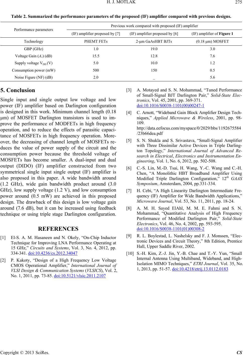
ized the performance parameters of the proposed (IF) amplifier compared with previous designs.
Previous work compared with proposed (IF) amplifier
Table 2. Summar
Performance parameters
(IF) amplifier proposed mplifier of Figure 1 by [7] (IF) amplifier proposed by [6] (IF) a
Technology PHEMT FETs 2-μm GaAsHBT BJTs (0.18 μm) MOSFET
GBP (GHz) 1.0 19.0 3.0
Volta dB)
C
ge Gain (Av) (15.5 12.8 7.6
Supply voltage VDD (V) 5.0 10.0 1.2
onsumption power (mW)500 150 0.5
Noise Figure (NF) (dB) 2.0 _ 5.6
ngle output low voltage and low
[1] El-S. A. M. H
5. Conclusion
Single input and si
power (IF) amplifier based on Darlington configuration
is designed in this work. Minimum channel length (0.18
μm) of MOSFET Darlington transistors is used to im-
prove the performance of MODFETs in high frequency
operation, and to reduce the effects of parasitic capaci-
tance of MOSFETs in high frequency operation. More-
over, the decreasing of channel length of MOSFETs re-
duces the value of power supply of the circuit and the
consumption power because the threshold voltage of
MOSFETs has become smaller. A dual-input and dual
output (DIDO) (IF) amplifier constructed from two
symmetrical single input single output (IF) amplifier is
also proposed in this paper. A wide bandwidth around
(1.2 GHz), wide gain bandwidth product around (3.0
GHz), low supply voltage (1.2 V), and low consumption
power around (0.5 mW) are achieved in this proposed
design. The drawback of this design is low voltage gain
around (7.6 dB), but it can be increased using feedback
technique or using triple stage Darlington configuration.
REFERENCES
asaneen and N. Okely, “On-Chip Inductor
Technique for Improving LNA Performance Operating at
15 GHz,” Circuits and Systems, Vol. 3, No. 4, 2012, pp.
334-341. doi:10.4236/cs.2012.34047
[2] P. Kakoty, “Design of a High Frequency Low Voltage
CMOS Operational Amplifier,” International Journal of
VLSI Design & Communication Systems (VLSICS), Vol. 2,
No. 1, 2011, pp. 73-85. doi:10.5121/vlsic.2011.2107
[3] A. Motayed and S. N. Mohammad, “Tuned Performance
of Small-Signal BJT Darlington Pair,” Solid-State Elec-
tronics, Vol. 45, 2001, pp. 369-371.
doi:10.1016/S0038-1101(00)00247-1
lifier Design Tech-
data.eefocus.com/myspace/0/2029/bbs/1192675584
d S. Srivastava, “Small-Signal Amplifier
g and C.-H.
mediate Fre-
N.
[4] C. Arnott, “Wideband Gain Block Amp
niques,” Applied Microwave & Wireless, 2001, pp. 98-
109.
http://
/23b66dea.pdf
[5] S. N. Shukla an
with Three Dissimilar Active Devices in Triple Darling-
ton Topology,” International Journal of Advanced Re-
search in Electrical, Electronics and Instrumentation En-
gineering, Vol. 1, No. 6, 2012, pp. 502-508.
[6] C.-S. Lin, M.-D. Tsai, H. Wang, Y.-C. Wan
Chen, “A Monolithic HBT Broadband Amplifier Using
Modified Triple Darlington Configuration,” 12th GAAS
Symposium, Amsterdam, 2004, pp.331-334.
[7] H. Cebi, “A High Linearity Darlington Inter
quency (IF) Amplifier for Wide Bandwidth Applications,”
Microwave Journal, Vol. 53, No. 11, 2011, pp. 18-24.
[8] A. M. H. Sayed ElAhl, M. M. E. Fahmi and S.
Mohammad, “Quantitative Analysis of High Frequency
Performance of Modified Darlington Pair,” Solid-State
Electronics, Vol. 46, No. 4, 2002, pp. 593-595.
doi:10.1016/S0038-1101(01)00308-2
[9] R. L. Boylestad, L. Nashelsky and F. J. Monssen, “Elec-
and T.-Y. Yun, “Small
tronic Devices and Circuit Theory,” 8th Edition, Prentice
Hall, Upper Saddle River, 2002.
[10] S.-H. Kim, Z.-J. Jin, Y.-B. Chae
Internal Antenna Using Multiband, Wideband, and High-
Isolation MIMO Techniques,” ETRI Journal, Vol. 35, No.
1, 2013, pp. 51-57. doi:10.4218/etrij.13.0112.0183