 Journal of Water Resource and Protection, 2013, 5, 689-698 http://dx.doi.org/10.4236/jwarp.2013.57069 Published Online July 2013 (http://www.scirp.org/journal/jwarp) Design and Evaluation of Dadu Canal Lining for Sustainable Water Saving Ashfaque A. Memon1, Khalifa Q. Leghari1, Agha F. H. Pathan1, Kanya L. Khatri2, Sadiq A. Shah2, Kanwal K. Pinjani3, Rabi a Soomro2, Kameran Ansari1 1Department of Civil Engineering, Mehran UET, Jamshoro, Sindh, Pakistan 2Department of Civil Engineering, Mehran UET Khairpur Campus, Sindh, Pakistan 3Water Resources Division, National Engineering Services, Lahore, Pakistan Email: rajaln@yahoo.com, ashfaquememon144@gmail.com Received April 25, 2013; revised May 27, 2013; accepted June 20, 2013 Copyright © 2013 Ashfaque A. Memon et al. This is an open access article distributed under the Creative Commons Attribution License, which permits unrestricted use, distribution, and reproduction in any medium, provided the original work is properly cited. ABSTRACT Pakistan livelihood depends on agriculture and so for this on irrigation system. The irrigation system in Sindh province depends on three barrages. The canals off taking from these three barrages irrigate 5.5 million hectares of agriculture land. Sukkur Barrage, which is the oldest one, irrigates more than 2.0 million hectares of land. The Dadu Canal off tak- ing from Sukkur barrage is an earthen canal. A huge amount of irrigation water is lost from the canal in the form of seepage from banks and bed. It is estimated that 40 to 50 per cent of water is lost between the canal head works to the farm-gate. The seepage from the canal creates twin problems of salinity and water logging consequently a large agri- culture land has gone out of use, and this process is continued particularly in Sindh. Lining of Canals is considered an effective solution to this problem. But lining of canals in Sindh is a great issue as canals will need to be closed long enough to deprive the farmers at least one crop season and the farmers are unable to pay this price for canal. Therefore, in this study, the Dadu Canal is proposed to be redesigned as an adjacent lined canal which involves design of cross section for various lining options at locations where changes in the hydraulic conditions occur at cross regulators and fall structures. The proposed lining is preferred to be plain cement concrete lining which is selected after investigating local conditions. Quantity and cost estimation at selected RDs (Reduced Distance) proved feasible and significant in long term functioning of Dadu Canal. Keywords: Dadu Canal; Concrete Lining; Canal Design; Lining Evaluation; Sustainable Water Saving 1. Introduction Indus basin irrigation system (IBIS), being one of the world’s largest irrigation systems, encompasses 12,676 km, 33,884 km and 122,268 km length of canals at Pri- mary, Secondary and Tertiary levels, respectively [1]. Along with a number of operational problems in IBIS, high rate of seepage occurs while conveyance of ap- proximately 0.123 Million Hectare Meter (MHM) annu- ally [2-6]. Due to excess seepage losses through canals along a lot of agricultural land water table has turn ed into within one meter depth. Such a serious scenario has re- sulted into considerable decline in yields of all crops ex- cept that of rice [7]. Furthermore, joint adverse effect of water logging and conseq uent salinity is more substantial than that of water logging only [7]. Hence, it is stated that in Pakistan there is large and cost-effective capacity to enhance water deliveries to agricultural farms by re- ducing conveyance losses while flow through canal sys- tem [4,8]. As a usual trend along river banks, irrigated agricul- ture indicated the era of development of human civiliza- tion in Sindh also. Early agriculture involving mainly food production changed slowly to modern agriculture through a continuous evolution of agriculture technolo- gies. The present irrigation system in Sindh depends on three barrages namely Sukkur, Kotri and Guddu con- structed in 1932, 1955 and 1962 respectively. Except Akram wah (canal) off taking from Kotri Barrage, all other canals are earthen canals. Large amount of irriga- tion water is lost from these canals in the form of seepage from banks and bed. It is estimated that 40 to 50 per cent of water is lost between the canal head works to the croplands [9]. Prabhata et al. [10] recommend that canals of new ir- rigation project in arid or semi-arid regions must be lined to avoid chances of abundant seepage in case of dry soil C opyright © 2013 SciRes. JWARP 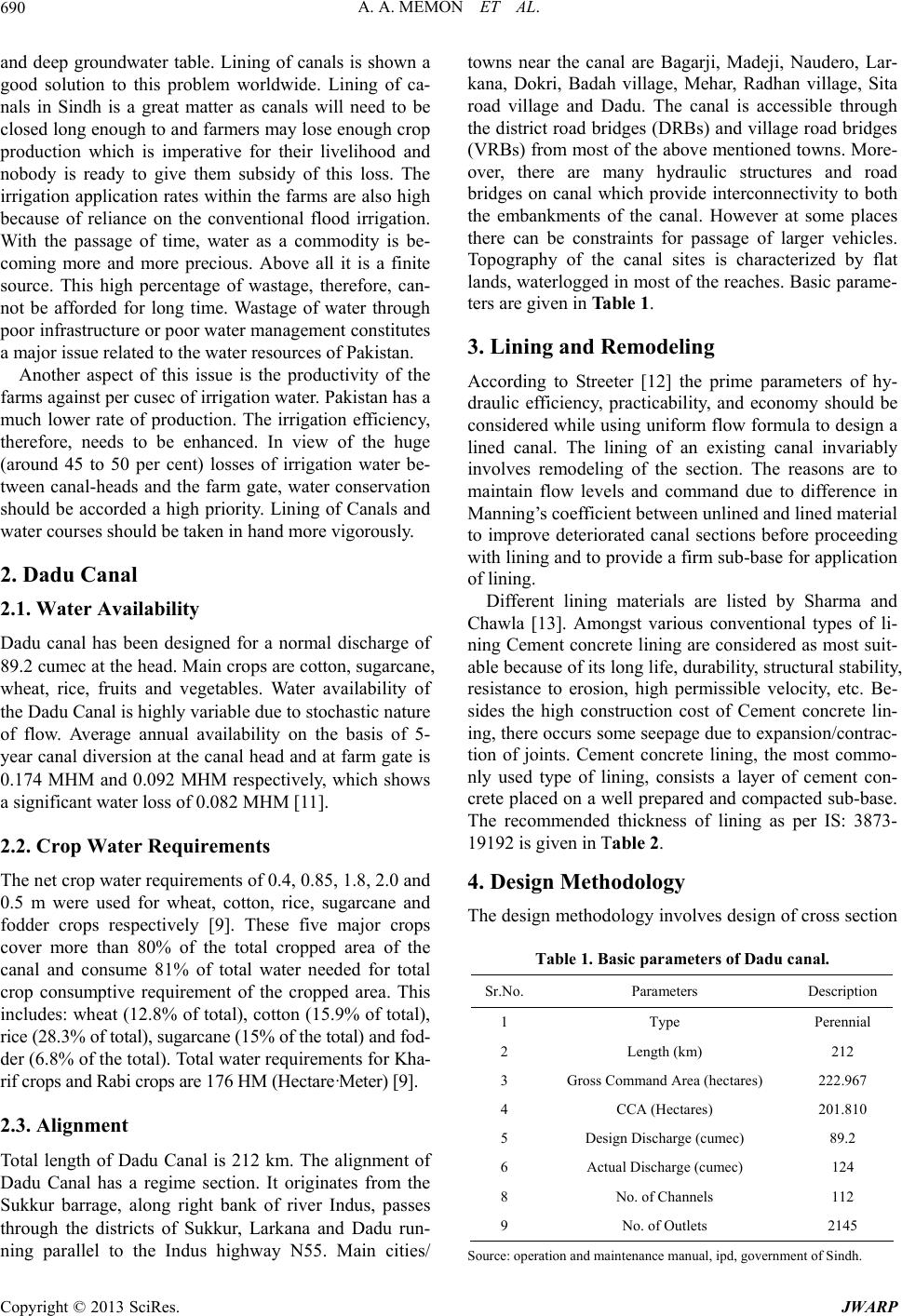 A. A. MEMON ET AL. 690 and deep groundwater table. Lining of canals is shown a good solution to this problem worldwide. Lining of ca- nals in Sindh is a great matter as canals will need to be closed long enough to and farmers may lose en ough crop production which is imperative for their livelihood and nobody is ready to give them subsidy of this loss. The irrigation application rates within the farms are also high because of reliance on the conventional flood irrigation. With the passage of time, water as a commodity is be- coming more and more precious. Above all it is a finite source. This high percentage of wastage, therefore, can- not be afforded for long time. Wastage of water through poor infrastructur e or poor water manage ment con stitutes a major issue related to the water resources of Pakistan. Another aspect of this issue is the productivity of the farms against per cusec of irrigation water. Pakistan has a much lower rate of production. The irrigation efficiency, therefore, needs to be enhanced. In view of the huge (around 45 to 50 per cent) losses of irrigation water be- tween canal-heads and the farm gate, water conservation should be accorded a high priority. Lining of Canals and water courses should be taken in hand more vigorously. 2. Dadu Canal 2.1. Water Availability Dadu canal has been designed for a normal discharge of 89.2 cumec at the head. Main crops are cotton, sugarcane, wheat, rice, fruits and vegetables. Water availability of the Dadu Canal is highly variable due to stochastic nature of flow. Average annual availability on the basis of 5- year canal diversion at the canal head and at farm gate is 0.174 MHM and 0.092 MHM respectively, which shows a significant water loss of 0.082 MHM [11]. 2.2. Crop Water Requirements The net crop water requirements of 0.4, 0.85, 1.8, 2.0 and 0.5 m were used for wheat, cotton, rice, sugarcane and fodder crops respectively [9]. These five major crops cover more than 80% of the total cropped area of the canal and consume 81% of total water needed for total crop consumptive requirement of the cropped area. This includes: wheat (12.8% of total), cotto n (15.9% of total), rice (28.3% of total), sugarcane (15% of the total) and fod- der (6.8% of the total). To tal water requirements fo r Kha- rif crops and Rabi crops are 176 HM (Hectare·M et er) [9]. 2.3. Alignment Total length of Dadu Canal is 212 km. The alignment of Dadu Canal has a regime section. It originates from the Sukkur barrage, along right bank of river Indus, passes through the districts of Sukkur, Larkana and Dadu run- ning parallel to the Indus highway N55. Main cities/ towns near the canal are Bagarji, Madeji, Naudero, Lar- kana, Dokri, Badah village, Mehar, Radhan village, Sita road village and Dadu. The canal is accessible through the district road bridges (DRBs) and village ro ad bridges (VRBs) from most of the above mentioned towns. More- over, there are many hydraulic structures and road bridges on canal which provide interconnectivity to both the embankments of the canal. However at some places there can be constraints for passage of larger vehicles. Topography of the canal sites is characterized by flat lands, waterlogged in most of the reaches. Basic parame- ters are given in Table 1. 3. Lining and Remodeling According to Streeter [12] the prime parameters of hy- draulic efficiency, practicability, and economy should be considered while using uniform flow formula to design a lined canal. The lining of an existing canal invariably involves remodeling of the section. The reasons are to maintain flow levels and command due to difference in Manning’s coefficient between unlined and lined material to improve deteriorated canal sections before proceeding with lining and to provid e a firm sub-base for application of lining. Different lining materials are listed by Sharma and Chawla [13]. Amongst various conventional types of li- ning Cement concrete lining are considered as most suit- able because of its long life, durability, structural stability, resistance to erosion, high permissible velocity, etc. Be- sides the high construction cost of Cement concrete lin- ing, there occurs some seepage due to expansion/contrac- tion of joints. Cement concrete lining, the most commo- nly used type of lining, consists a layer of cement con- crete placed on a well prepared and compacted sub-base. The recommended thickness of lining as per IS: 3873- 19192 is gi ven in Table 2. 4. Design Methodology The design methodo logy involves d esign of cross sectio n Table 1. Basic parameters of Dadu canal. Sr.No.Parameters Description 1 Type Perennial 2 Length (km) 212 3 Gross Command Area (hectares) 222.967 4 CCA (Hectares) 201.810 5 Design Discharge (cumec) 89.2 6 Actual Discharge (cumec) 124 8 No. of Channels 112 9 No. of Outlets 2145 Source: operation and maintenance manual, ipd, government of Sindh. Copyright © 2013 SciRes. JWARP 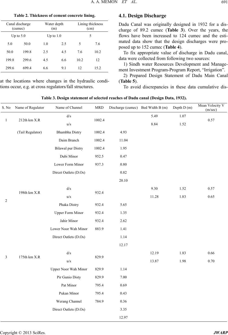 A. A. MEMON ET AL. Copyright © 2013 SciRes. JWARP 691 Table 2. Thickness of cement concrete lining. Canal discharge (cumec) Water depth (m) Lining thickness (cm) Up to 5.0 Up to 1.0 5 5.0 50.0 1.0 2.5 5 7.6 50.0 199.8 2.5 4.5 7.6 10.2 199.8 299.6 4.5 6.6 10.2 12 299.6 699.4 6.6 9.1 12 15.2 at the locations where changes in the hydraulic condi- tions occur, e.g. at cross regulators/fall structures. 4.1. Design Discharge Dadu Canal was originally designed in 1932 for a dis- charge of 89.2 cumec (Table 3). Over the years, the flows have been increased to 124 cumec and the esti- mated data show that the design discharges were pro- posed up to 152 cumec (Table 4). To fix appropriate value of discharge in Dadu canal, data were collected from following two sources: 1) Sindh water Resources Development and Manage- ment Investment Program-Program Report, “Irrigation”. 2) Prepared Design Statement of Dadu Main Canal (Table 5). To avoid discrepancies in these data cumulative dis- Table 3. Design statement of selected reaches of Dadu canal (Design Data, 1932). S. No Name of Regulator Name of Channel MRD Discharge (cumec)Bed Width B (m)Depth D (m) Mean Velocity V (m/sec) d/s 5.49 1.07 1 212th km X.R u/s 1002.4 8.84 1.52 0.57 (Tail Regulator) Bhambha Distry 1002.4 4.93 Daim Branch 1002.4 11.04 Bilawal pur Distry 1002.4 1.95 Dubi Minor 952.5 0.47 Lower Form Minor 937.3 0.80 Dircet Outlets (D.Os) 0.82 20.10 d/s 9.30 1.52 0.57 198th km X. R u/s 932.4 11.28 1.83 0.65 2 Phaka Distry 932.4 5.65 Upper Form Minor 932.4 1.35 Jahir Minor 932.4 2.62 Lower Noor Wah Minor 883.9 1.41 Direct Outlets (D.Os) 1.14 12.17 d/s 12.19 1.83 0.66 3 175th km X.R u/s 829.9 13.87 1.98 0.70 Upper Noor Wah Minor 829.9 1.14 Pir Gunio Disty 829.9 7.00 Pat Minor 795.4 0.69 Pukan Minor 795.4 0.43 Werang Channel 784.9 0.36 Direct Outlets (D.Os) 3.35 12.97 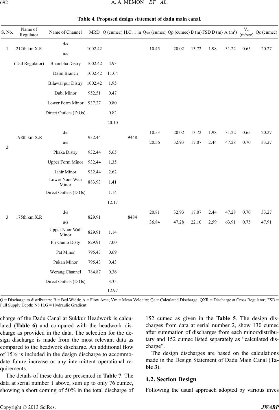 A. A. MEMON ET AL. 692 Table 4. Proposed design statement of dadu main canal. S. No. Name of Regulator Name of Channel MRD Q (cumec)H.G. 1 inQXR (cumec)Qp (cumec)B (m)FSD D (m) A (m2) Vm (m/sec) Qc (cumec) d/s 1 212th km X .R u/s 1002.42 10.45 20.02 13.721.98 31.22 0.65 20.27 (Tail Regulator) Bhambha Distry 1002.42 4.93 Daim Branch 1002.42 11.04 Bilawal pur Distr y 1002.42 1.95 Dubi Minor 952.51 0.47 Lower Form Minor 937.27 0.80 Direct Outlets (D.Os) 0.82 20.10 d/s 10.53 20.02 13.721.98 31.22 0.65 20.27 198th km X. R u/s 932.44 9448 20.56 32.93 17.072.44 47.28 0.70 33.27 2 Phaka Distry 932.44 5.65 Upper Form Minor 932.44 1.35 Jahir Minor 932.44 2.62 Lower Noor Wah Minor 883.93 1.41 Direct Outlets (D.Os) 1.14 12.17 d/s 20.81 32.93 17.072.44 47.28 0.70 33.27 3 175th km X .R u/s 829.91 8484 36.84 47.28 22.102.59 63.91 0.75 47.91 Upper Noor Wah Minor 829.91 1.14 Pir Gunio Disty 829. 9 1 7.00 Pat Minor 795.43 0.69 Pukan Minor 795.43 0.43 Werang Channel 784.87 0.36 Direct Outlets (D.Os) 3.35 12.97 Q = Discharge to distributary; B = Bed Width; A = Flow Area; Vm = Mean Velocity; Qc = Calculated Discharge; QXR = Discharge at Cross Reg u l at or ; FSD = Full Supply Depth; N8 H.G = Hydraulic Gradient charge of the Dadu Canal at Sukkur Headwork is calcu- lated (Table 6) and compared with the headwork dis- charge as provided in the data. The selection for the de- sign discharge is made from the most relevant data as compared to the headwork discharge. An additional flow of 15% is included in the design discharge to accommo- date future increase or any intermittent operational re- quirements. The details of these data are presented in Table 7. The data at serial number 1 above, sum up to only 76 cumec, showing a short coming of 50% in the total discharge of 152 cumec as given in the Table 5. The design dis- charges from data at serial number 2, show 130 cumec after summation of discharges from each minor/distribu- tary and 152 cumec listed separately as “calculated dis- charge”. The design discharges are based on the calculations made in the Design Statement of Dadu Main Canal (Ta- ble 3). 4.2. Section Design Following the usual approach adopted by various inves Copyright © 2013 SciRes. JWARP  A. A. MEMON ET AL. 693 Table 5. Prepared design statement of Dadu canal w.r.to existing data. S. No. Name of Regulator Name of Channel MRDDischarge (cumec) H.G. 1 inDischarge (cumec) Bed width B (m)Depth (m) d/s 3.09 6.0 1 212th km X.R u/s 1002.4 8.98 3.8 (Tail Regulator) Bhambha Distry 1002.44.93 Daim Branch 1002.411.04 Bilawal pur Distry 1002.41.95 Dubi Minor 952.5 0.47 Lower Form Minor 937.3 0.80 Dircet Outlets (D.Os) 0.82 20.10 d/s 9.43 7.1 3.8 198th km X. R u/s 932.4 10000 14.78 8.1 4.3 2 Phaka Distry 932.45.65 Upper Form Minor 932.4 1.35 Jahir Minor 932.4 2.62 Lower Noor Wah Minor 883.9 1.41 Direct Outlets (D.Os) 1.14 12.17 d/s 16.79 8.7 4.3 3 175th km X.R u/s 829.9 10000 22.03 12.8 6 Upper Noor Wah Minor 829.9 1.14 Pir Gunio Disty 829.9 7.00 Pat Minor 795.4 0.69 Pukan Minor 795.4 0.43 Werang Channel 784.9 0.36 Direct Outlets (D.Os) 3.35 12.97 tigators [14-16], in this case the section design for lining option is also based on Manning’s formula: 23 12 1 486. VRS n = where V is velocity of flow (ft/sec); n is Manning’s coef- ficient; S is longitudinal hydraulic slope or canal bed slope (ft per ft); R is hydraulic radius (ft) = A/P; A is area of the flow section (ft2), and P is wetted perimeter (ft). 4.3. Manning’s Coefficient Different characteristics, to make a lined canal section hydraulically most economical, suggested by Chow [17], French [18] and Guo and Hughes [19], include perme- ability, Manning’s coefficient, durability, cost of con- struction and maintenance, etc. The permeability of ma- terial determines absorption losses and the Manning’s co- efficient determines the carrying capacity of the channel. Weathering is caused by disruptive action of temperature variation, alternate freezing and thawing, and wetting and drying. The alkali soil causes corrosion of concrete and this can be prevented by the application of sulphate re- sistant cement (SRC). Cost of construction would vary with the locality and th e availability of various materials. The thickness of lined section would depend upon the lining material, the side slope and the existence of hy Copyright © 2013 SciRes. JWARP  A. A. MEMON ET AL. 694 Table 6. Comparative statement of dadu canal. Discharge (cumec) Bed Width (m) Depth (m) Mean Veloc ity (m) S. No. Name of Regulator Name of Channel MRD Des.Exis.Prop. Des.Exis. Prop.Des.Exis. Prop. Des. Exis.Prop. d/s 3.095.4912.191.07 1 212th km X.R u/s 1002.41 8.98 20.27 8.8414.63 13.72 1.52 1.16 1.98 0.57 0.100.65 (Tail Regulator) Bhambha Distry 1002.41 4.93 Daim Branch 1002.41 11.04 Bilawal pur Distry 1002. 41 1.95 Dubi Minor 952.50 0.47 Lower Form Minor 937.26 0.80 Dircet Outlets (D.Os) 0.82 20.10 d/s 9.4320.279.3014.6313.721.521.16 1.98 0.57 0.280.65 2 198th km X.R u/s 932.43 14.7833.2711.2819.2017.07 1.831.31 2.44 0.65 0.340.70 Phaka Distry 932.43 5.65 Upper Form Minor 932.43 1.35 Jahir Minor 932.43 2.62 Lower Noor Wah Minor 883.92 1.41 Direct Outlets (D.Os) 1.14 12.17 d/s 16.7933.2712.1921.6417.071.831.31 2.44 0.66 0.360.70 3 175th km X.R u/s 829.90 22.0347.9113.8724.0822.10 1.981.83 2.59 0.70 0.230.75 Upper Noor Wah Minor 829.90 1.14 Pir Gunio Disty 829.90 7.00 Pat Minor 795.42 0.69 Pukan Minor 795.42 0.43 Werang Channel 784.86 0.36 Direct Outlets (D.Os) 3.35 12.97 dro-static pressure. There should be proper drainage sys- tem to prevent failure due to back pressure. Concrete lining is durable and, if laid properly, the absorption losses are reduced by 95%. The Manning’s coefficient is low and in view of high permissible veloci- ties, the section is reduced. The construction is carried out in panels and grooves are provided to prevent cracks due to shrinkage and alternate expansion and contraction. Oil paper, crude oil, 1:6 cement plaster or 1:4 cement sand slurry are used at the top of sub grade to avoid its becoming spongy and permeable. 4.4. Canal Section Properties The remodeling of canal section imposes certain restric- tion on the selection of various dimensions; the last de- signed section dictating most of the values like longitu- dinal slope, full supply depth and full supply levels. These parameters and the values adopted considering the above points are detailed below. 4.5. Depth of Flow The excessive widening of the existing canal section provides a possibility of selecting a larger bed width with a reduced water depth. In some reaches the silting of ca- nal bed compensates for the reduction in the depth with raised bed levels. The resulting lowering of full supply level, is therefore not so different when compared with full supply levels of last design. A slight reduction in full Copyright © 2013 SciRes. JWARP  A. A. MEMON ET AL. 695 Table 7. Proposed Discharges shown at Barrage Headworks, Cross Regulators and Tail Regulator. RD Discharge (Cusecs) At Downstream of Structure 0 + 000 537 8 Sukkur Barrage Headworks 19 + 597 5265 39 mile Naudero Cross Regulator 250 + 600 5063 51 mile Pir Sher Cross Regulator 283 + 405 4482 57 mile Pandabad Cross Regulator 331 + 992 4497 67 mile Sonahri Cross Regulator 383 + 460 4127 77 mile Tatri Cross Regul a tor 420 + 534 3717 95 mi l e Waha Cross Regulator 473 + 630 3564 95 mile Cross Regulator 546 + 000 1692 109 mile Cross Regulator 611 + 830 1175 123 mile Cross Regulator 657 + 750 716 132 mile Tail Regulator supply level has been allowed in the design to reduce the extent of the works required for remodeling of the sec- tion. The head ponds created upstream of cross regulators provides control of the required full supply levels for feeding into minors and distributaries. The effects of lowering in the full sup ply depth, at locations away from the head ponds, will be checked to ensure supplies from direct outlets. The design with reduced flow depth for same flows, results in increased wetted perimeter and a subsequent increase in the cost of expensive lining. The changes in full supply depth are therefore kept to a minimum. The bed widths are selected between the maximum available due to widening of canals and minimum required for maintaining the desired supply depth. 4.6. Side Slopes Side slope is provided on the consideration of angle of repose of the bank material as it results in a stable bank under dry conditions. The following side slopes are adopted for the lining under dry condition option and th e embankment material (sand fill) used in the remodeling: 1) Concrete lined, new parallel canal 2 H:1V (Utilizing minimum right of way, achieve stability un- der drawdown conditions and provide ease in construc- tion) 2) Unlined diversion channel In cutting 1 H:1 V In filling 1.5 H:1 V 4.7. Canal Longitudinal Slope A lined canal can have steeper longitudinal slopes (L- slopes) than unlined canals, as higher velocities which may cause erosion of unlined canals, are not a problem. The existing canals have a large number of cross regula- tors with combination of fall structures, having upstream and downstream controlling levels. The existin g bed lev- els suggest uneven L-slope as well as reverse slopes in small reaches due to uneven silting. The silting is mainly limited to upper reaches and scouring at lower reaches. In reaches having scouring in almost the entire reach, the same L-slopes are adopted as that of last design, and the bed levels are also kept the same. 4.8. Freeboard Considering the size and discharge of the canal, the value of free board may be roughly taken as one-sixth of flow depth. Recommended values of freeboard are as follows Discharge (cumec) Free Board (m) 450 to 255 0.91 255 to 170 0.84 <170 0.76 The freeboard provided in the design includes 80% of the above values for the freeboard plus calculated depths required for passing additional 15% flows. The resulting freeboard is then checked for the depths required during various stages of remodeling, allowing 50% of the free- board for any such possible increase. 4.9. Velocity of Flow Since, higher permissible velocities reduce silt deposition in the bed of lined canal and all the silt is passed on to the lower reaches and into the distributaries and minors, it necessitates lining of minors and distributaries to avoid rising of bed leve ls which may affect the comman d of the irrigati o n ne t work. To limit this phenomenon to a minimum there is no drastic increase in the existing velocities in the remod- eled section. The present velocities of around 1.0 m/sec are generally increased by 15% to 25%, to remain below 2.2 m/sec. However in some upper reaches with heavy silting of canal bed, the longitudinal slope has been in- creased to minimize the required remodeling work. In such reaches, up to 40% increase in the existing flow velocities are allowed with maximum velocity not to exceed 1.4 m/sec. The velocity of flows during remodeling is also checked. Velocities greater than 1.1 m/sec are not consi- dered suitable for remodeled section with available near- by material or graded soil, before application of lining. 5. Hydraulic Design Worksheets The design for remodeled sections downstream of cross regulator or fall structures is done through MS Excel Copyright © 2013 SciRes. JWARP  A. A. MEMON ET AL. Copyright © 2013 SciRes. JWARP 696 worksheet developed for this purpose. There are three main reaches of Dadu Canal first at “123rd Mile X.R”, second at “85th Mile X.R”, and third at “57th Mile X.R”. The worksheet includes design for the plain concrete lining with rec om mended value of “n” as 0.01 7. 5.1. Design Procedure The design worksheet of selected reaches, as shown in Table 4, is calculated adopting following procedure. 8.0 ft 1 For the assumed value of bottom width of channel sec- tion, discharge (Q) is calculated using continuity equa- tion. The computed discharge is compared with required discharge (Qreq); if both discharges are equal it means that the design of selected section is correct and if not then revise the bottom width. 40.7 ftH 1 TS Figure 1. The simplest version of the designed cross section by Flow Master. 5.2. Checking of Design Parameters Plain cement concrete lining. For this purpose the quan- tity of cutting (trimming), backfilling at the sides of the canal and quantity of concrete lining perimeter are worked out. The thickness of 13 cm is taken for estimate- ing the concrete quantity having strength of 3000 psi in selected reaches. The checking of designed worksheet parameters (i.e. Bed width, Flow area, Wetted perimeter, Hydraulic radius, and Flow velocity) has been done by using “Flow Master Software (2009)”. One of the trial sections and final re- modeled sections computed by the software are shown in Figures 1 and 2, respectively. These hydraulic design parameters are compared with those at design stage and existing data as shown in Table 6. 6.1. Quantities The quantities of the selected reaches up to MRDs 457, 503, 655, 686, 953 and 983 along the length of canal are worked out in MS EXCEL worksheet as shown in Table 8. 6. Quantity and Cost Estimation Preliminary cost estimates have been prepared for the Figure 2. Remodeled cr oss-section by flow master with complete design. 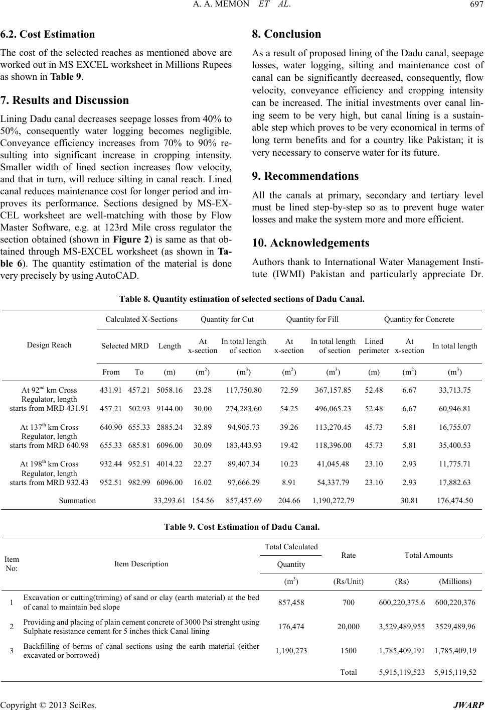 A. A. MEMON ET AL. 697 6.2. Cost Estimation The cost of the selected reaches as mentioned above are worked out in MS EXCEL worksheet in Millions Rupees as shown in Table 9. 7. Results and Discussion Lining Dadu canal decreases seepage losses from 40% to 50%, consequently water logging becomes negligible. Conveyance efficiency increases from 70% to 90% re- sulting into significant increase in cropping intensity. Smaller width of lined section increases flow velocity, and that in turn, will reduce silting in canal reach. Lined canal reduces maintenance cost for longer period and im- proves its performance. Sections designed by MS-EX- CEL worksheet are well-matching with those by Flow Master Software, e.g. at 123rd Mile cross regulator the section obtained (shown in Figure 2) is same as that ob- tained through MS-EXCEL worksheet (as shown in Ta- ble 6). The quantity estimation of the material is done very preci s ely by using Aut oCAD. 8. Conclusion As a result of proposed lining of the Dadu canal, seepage losses, water logging, silting and maintenance cost of canal can be significantly decreased, consequently, flow velocity, conveyance efficiency and cropping intensity can be increased. The initial investments over canal lin- ing seem to be very high, but canal lining is a sustain- able step which prov es to be very economical in terms of long term benefits and for a country like Pakistan; it is very necessary to conserve water for its future. 9. Recommendations All the canals at primary, secondary and tertiary level must be lined step-by-step so as to prevent huge water losses and make the system more and more efficient. 10. Acknowledgements Authors thank to International Water Management Insti- tute (IWMI) Pakistan and particularly appreciate Dr. Table 8. Quantity estimation of selected sections of Dadu Canal. Calculated X-Sections Quantity for Cut Quantity for Fill Qu antit y fo r Con crete Selected MRD Length At x-section In total length of sectionAt x-section In total length of sectionLined perimeter At x-section In total length Design Reach FromTo (m) (m2) (m3) (m2) (m3) (m) (m2) (m3) 431.91457.21 5058.16 23.28117,750.8072.59 367,157.8552.48 6.67 33,713.75 At 92nd km Cross Regulator, length starts from MRD 431.91 457.21502.93 9144.00 30.00274,283.6054.25 496,065.2352.48 6.67 60,946.81 640.90655.33 2885.24 32.8994,905.73 39.26 113,270.4545.73 5.81 16,755.07 At 137th km Cross Regulator, length starts from MRD 640.98 655.33685.81 6096.00 30.09183,443.9319.42 118,396.0045.73 5.81 35,400.53 932.44952.51 4014.22 22.2789,407.34 10.23 41,045.4823.10 2.93 11,775.71 At 198th km Cross Regulator, length starts from MRD 932.43 952.51982.99 6096.00 16.0297,666.29 8.91 54,337.7923.10 2.93 17,882.63 Summation 33,293.61 154.56857,457.69204.66 1,190,272.79 30.81 176,474.50 Table 9. Cost Estimation of Dadu Canal. Total Calculated Quantity Rate Total Amounts Item No: Item Description (m3) (Rs/Unit) (Rs) (Millions) 1 Excavation or cutting(triming) of sand or clay (earth material) at the bed of canal to maintain bed slope 857,458 700 600,220,375.6 600,220,376 2 Providing and plac ing of plai n cem ent concre te of 3000 Psi stren ght using Sulphate resistance cement for 5 inches thick Canal lining 176,474 20,000 3,529,489,955 3529,489,96 3 Backfilling of berms of canal sections using the earth material (either excavated or borrowed) 1,190,273 1500 1,785,409,191 1,785,409,19 Total 5,915,119,523 5,915,119,52 Copyright © 2013 SciRes. JWARP 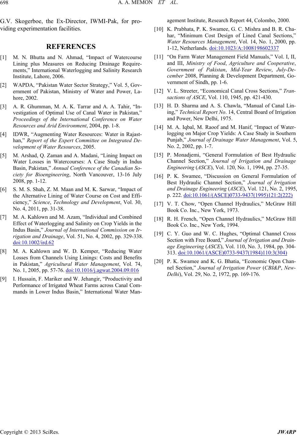 A. A. MEMON ET AL. 698 G.V. Skogerboe, the Ex-Director, IWMI-Pak, for pro- viding experimentation facilities. REFERENCES [1] M. N. Bhutta and N. Ahmad, “Impact of Watercourse Lining plus Measures on Reducing Drainage Require- ments,” Internat ional Waterlogging and Salinity Research Institute, Lahore, 2006. [2] WAPDA, “Pakis tan Water Sec tor Strategy,” Vol. 5, Gov- ernment of Pakistan, Ministry of Water and Power, La- hore, 2002. [3] A. R. Ghumman, M. A. K. Tarrar and A. A. Tahir, “In- vestigation of Optimal Use of Canal Water in Pakistan,” Proceedings of the International Conference on Water Resources and Arid Environment, 2004, pp. 1-8. [4] IDWR, “Augmenting Water Resources: Water in Rajast- han,” Report of the Expert Committee on Integrated De- velopment of Water Resources, 2005. [5] M. Arshad, Q. Zaman and A. Madani, “Lining Impact on Water Losses in Watercourses: A Case Study in Indus Basin, Pakistan,” Annual Conference of the Canadian So- ciety for Bioengineering, North Vancouver, 13-16 July 2008, pp. 1-12. [6] S. M. S. Shah, Z. M. Maan and M. K. Sarwar, “Impact of the Alternative Lining of Water Course on Cost and Effi- ciency,” Science, Technology and Development, Vol. 30, No. 4, 2011, pp. 31-38. [7] M. A. Kahlown and M. Azam, “Individual and Combined Effect of Waterlogging and Salinity on Crop Yields in the Indus Basin,” Journal of International Commission on Ir- rigation and Drainage, Vol. 51, No. 4, 2002, pp. 329-338. doi:10.1002/ird.62 [8] M. A. Kahlown and W. D. Kemper, “Reducing Water Losses from Channels Using Linings: Costs and Benefits in Pakistan,” Agricultural Water Management, Vol. 74, No. 1, 2005, pp. 57-76. doi:10.1016/j.agwat.2004.09.016 [9] I. Hussain, F. Mariker and W. Jehangir, “Productivity and Performance of Irrigated Wheat Farms across Canal Com- mands in Lower Indus Basin,” International Water Man- agement Institute, Research Report 44, Colombo, 2000. [10] K. Prabhata, P. K. Swamee, G. C. Mishra and B. R. Cha- har, “Minimum Cost Design of Lined Canal Sections,” Water Resources Management, Vol. 14, No. 1, 2000, pp. 1-12, Netherlands. doi:10.1023/A:1008198602337 [11] “On Farm Water Mana gement Field Manuals,” Vol. I, II, and III, Ministry of Food, Agriculture and Cooperative, Government of Pakistan, Mid-Year Review, July-De- cember 2008, Planning & Development Department, Go- vernment of Sindh, pp. 1-6. [12] V. L. Streeter, “Economical Canal Cross Sections,” Tran- sactions of ASCE, Vol. 110, 1945, pp. 421-430. [13] H. D. Sharma and A. S. Chawla, “Manual of Canal Lin- ing,” Technical Report No. 14, Central Board of Irrigation and Power, New Delhi, 1975. [14] M. A. Iqbal, M. Raoof and M. Hanif, “Impact of Water- logging on Major Crop Yields: A Case Study in Southern Punjab,” Journal of Drainage Water Management, Vol. 5, No. 2, 2002, pp. 1-7. [15] P. Monadjemi, “General Formulation of Best Hydraulic Channel Section,” Journal of Irrigation and Drainage Engineering (ASCE), Vol. 120, No. 1, 1994, pp. 27-35. [16] P. K. Swamee, “Discussion on General Formulation of Best Hydraulic Channel Section,” Journal of Irrigation and Drainage Engineering (ASCE), Vol. 121, No. 2, 1995, p. 222. doi:10.1061/(ASCE)0733-9437(1995)121:2(222) [17] V. T. Chow, “Open Channel Hydraulics,” McGraw Hill Book Co. Inc., New York, 1973. [18] R. H. French, “Open Channel Hydraulics,” McGraw Hill Book Co. Inc., New York, 1994. [19] C. Y. Guo and W. C. Hughes, “Optimal Channel Cross Section with Free Board,” Journal of Irrigation and Drain- age Engineering (ASCE), Vol. 110, No. 3, 1984, pp. 304- 313. doi:10.1061/(ASCE)0733-9437(1984)110:3(304) [20] P. K. Swamee and K. G. Bhatia, “Economic Open Chan- nel Section,” Journal of Irrigation Power (CBI&P, New- Delhi), Vol. 29, No. 2, 1972, pp. 169-176. Copyright © 2013 SciRes. JWARP
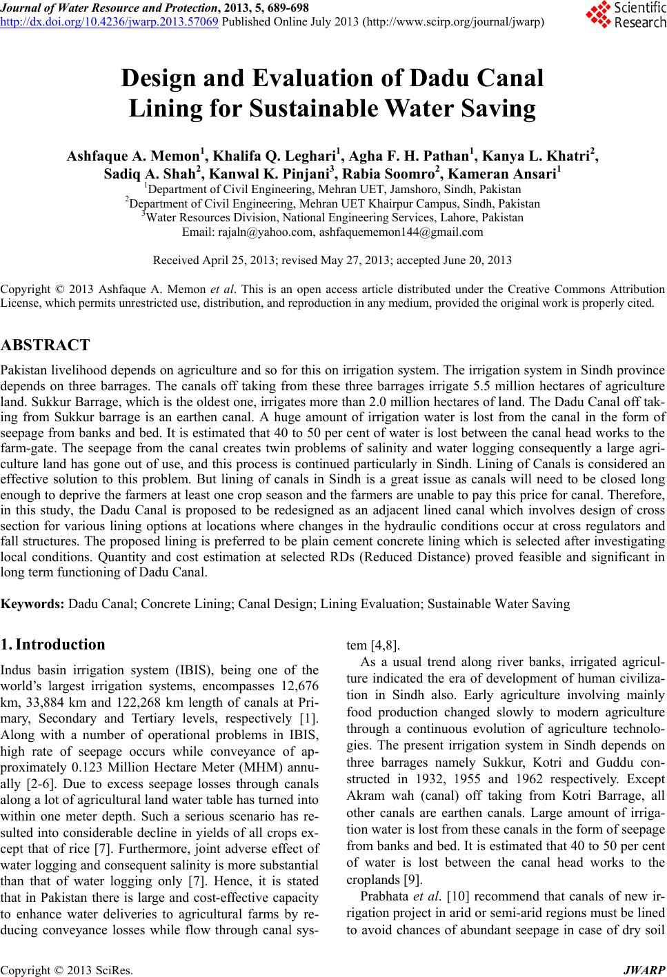
|