J. Z. MORO ET AL.
250
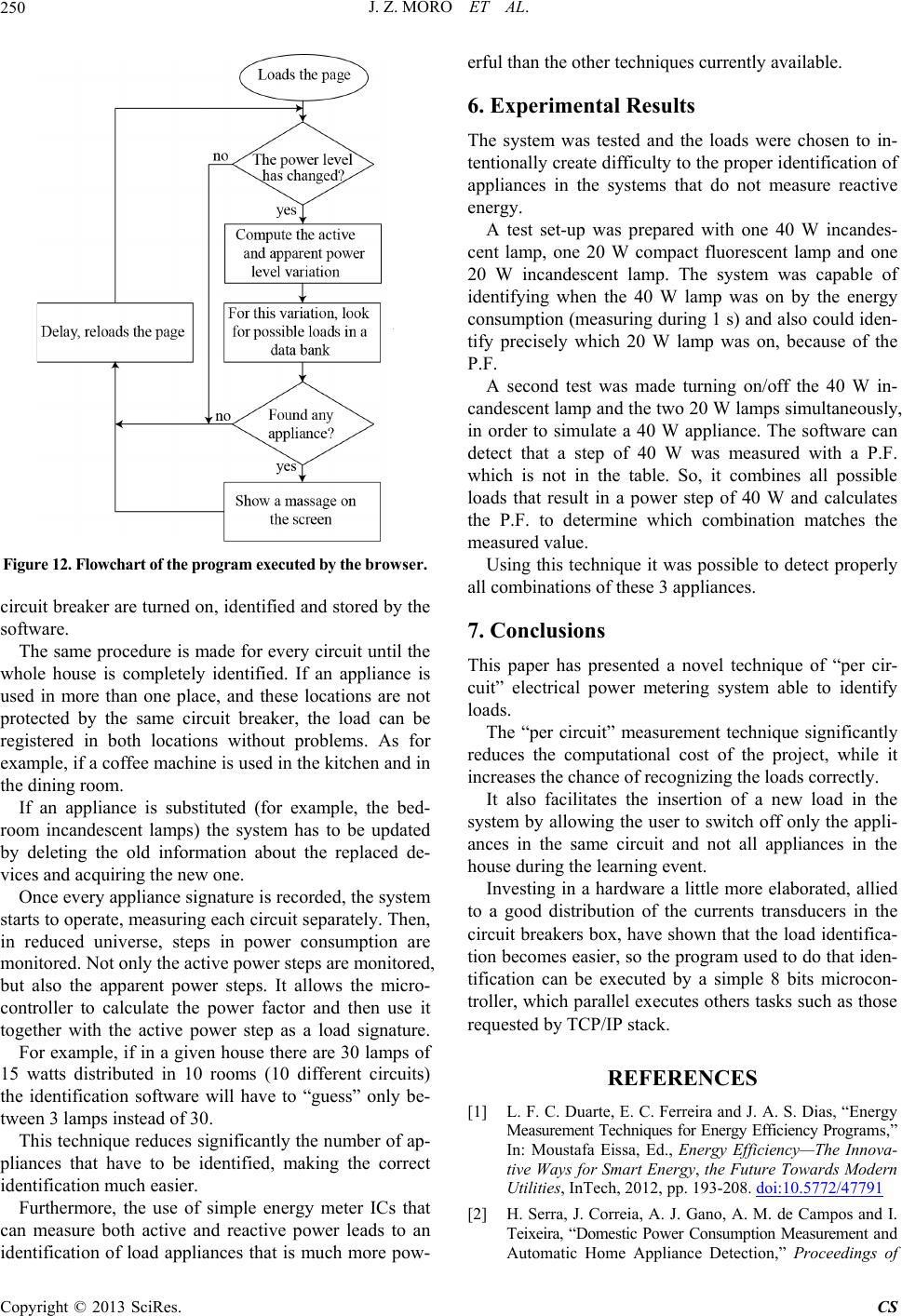
Figure 12. Flowchart of the program executed by the browser.
circuit breaker are turned on, identified and stored by the
software.
The same procedure is made for every circuit until the
whole house is completely identified. If an appliance is
used in more than one place, and these locations are not
protected by the same circuit breaker, the load can be
registered in both locations without problems. As for
example, if a coffee machine is used in the kitchen and in
the dining room.
If an appliance is substituted (for example, the bed-
room incandescent lamps) the system has to be updated
by deleting the old information about the replaced de-
vices and acquiring the new one.
Once every appliance signature is recorded, the system
starts to operate, measuring each circuit separately. Then,
in reduced universe, steps in power consumption are
monitored. Not only the active power steps are monitored,
but also the apparent power steps. It allows the micro-
controller to calculate the power factor and then use it
together with the active power step as a load signature.
For example, if in a given house there are 30 lamps of
15 watts distributed in 10 rooms (10 different circuits)
the identification software will have to “guess” only be-
tween 3 lamps instead of 30.
This technique reduces significantly the number of ap-
pliances that have to be identified, making the correct
identification much easier.
Furthermore, the use of simple energy meter ICs that
can measure both active and reactive power leads to an
identification of load appliances that is much more pow-
erful than the other techniques currently available.
6. Experimental Results
The system was tested and the loads were chosen to in-
tentionally create difficulty to the proper identification of
appliances in the systems that do not measure reactive
energy.
A test set-up was prepared with one 40 W incandes-
cent lamp, one 20 W compact fluorescent lamp and one
20 W incandescent lamp. The system was capable of
identifying when the 40 W lamp was on by the energy
consumption (measuring during 1 s) and also could iden-
tify precisely which 20 W lamp was on, because of the
P.F.
A second test was made turning on/off the 40 W in-
candescent lamp and the two 20 W lamps simultaneously,
in order to simulate a 40 W appliance. The software can
detect that a step of 40 W was measured with a P.F.
which is not in the table. So, it combines all possible
loads that result in a power step of 40 W and calculates
the P.F. to determine which combination matches the
measured value.
Using this technique it was possible to detect properly
all combinations of these 3 appliances.
7. Conclusions
This paper has presented a novel technique of “per cir-
cuit” electrical power metering system able to identify
loads.
The “per circuit” measurement technique significantly
reduces the computational cost of the project, while it
increases the chance of recognizing the loads correctly.
It also facilitates the insertion of a new load in the
system by allowing the user to switch off only the appli-
ances in the same circuit and not all appliances in the
house during the learning event.
Investing in a hardware a little more elaborated, allied
to a good distribution of the currents transducers in the
circuit breakers box, have shown that the load identifica-
tion becomes easier, so the program used to do that iden-
tification can be executed by a simple 8 bits microcon-
troller, which parallel executes others tasks such as those
requested by TCP/IP stack.
REFERENCES
[1] L. F. C. Duarte, E. C. Ferreira and J. A. S. Dias, “Energy
Measurement Techniques for Energy Efficiency Programs,”
In: Moustafa Eissa, Ed., Energy Efficiency—The Innova-
tive Ways for Smart Energy, the Future Towards Modern
Utilities, InTech, 2012, pp. 193-208. doi:10.5772/47791
[2] H. Serra, J. Correia, A. J. Gano, A. M. de Campos and I.
Teixeira, “Domestic Power Consumption Measurement and
Automatic Home Appliance Detection,” Proceedings of
Copyright © 2013 SciRes. CS