Paper Menu >>
Journal Menu >>
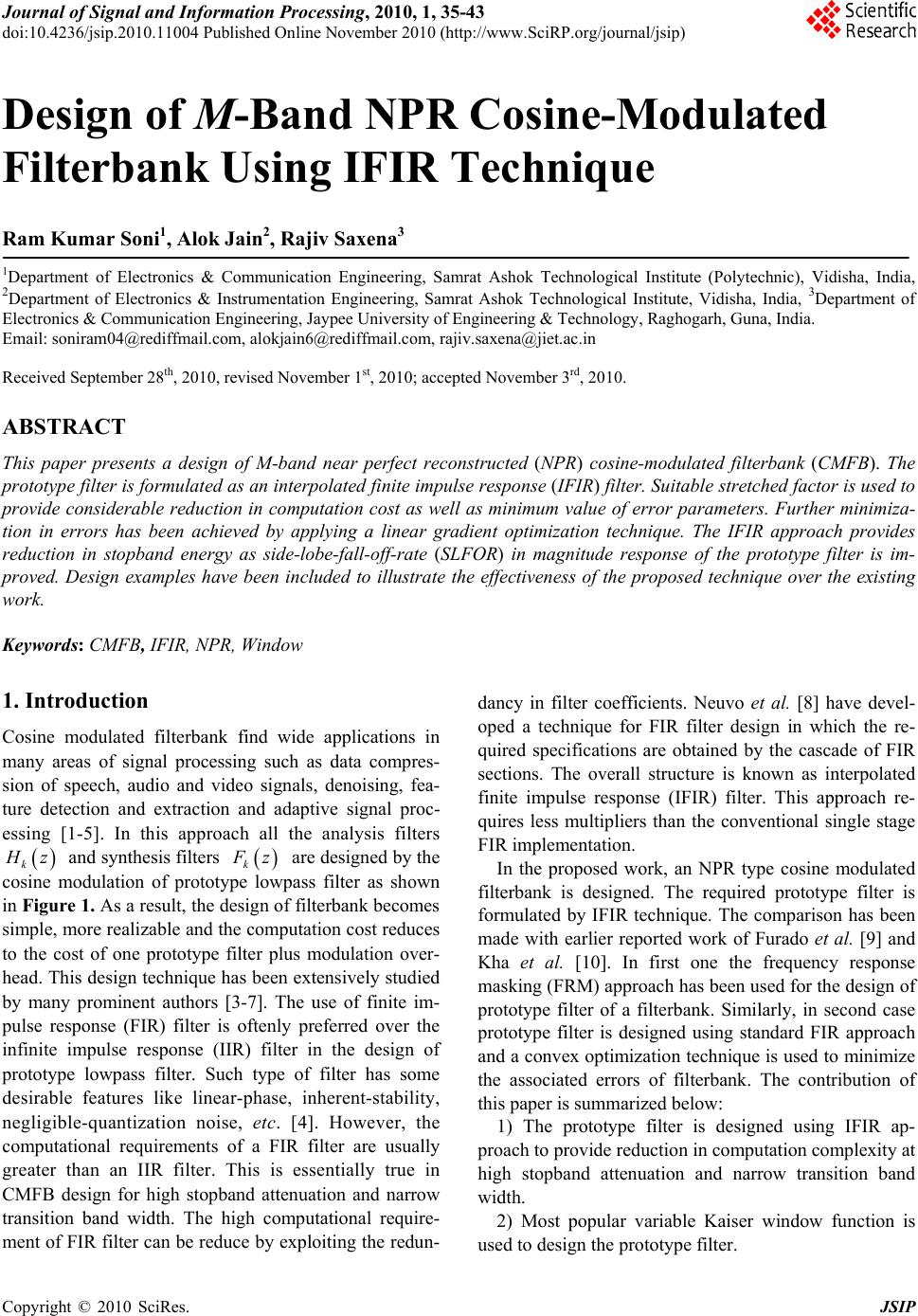 Journal of Signal and Information Processing, 20 10 , 1, 35 -43 doi:10.4236/jsip.2010.11004 Published Online November 2010 (http://www.SciRP.org/journal/jsip) Copyright © 2010 SciRes. JSIP 35 Design of M-Band NPR Cosine-Modulated Filterbank Using IFIR Technique Ram Kumar So ni1, Alok Jain2, Rajiv Saxena3 1Department of Electronics & Communication Engineering, Samrat Ashok Technological Institute (Polytechnic), Vidisha, India, 2Department of Electronics & Instrumentation Engineering, Samrat Ashok Technological Institute, Vidisha, India, 3Department of Electronics & Communication Engineering, Jaypee University of Engineering & Technology, Raghogarh, Guna, India. Email: soniram04@rediffmail.com, alokjain6@rediffmail.com, rajiv.saxena@jiet.ac.in Received September 28th, 2010, revised November 1st, 2010; accepted November 3rd, 2010. ABSTRACT This paper presents a design of M-band near perfect reconstructed (NPR) cosine-modulated filterbank (CMFB). The prototype filter is formulated as an interpolated finite impulse response (IFIR) filter. Suitable stretched factor is used to provide considerable reduction in computation cost as well as minimum value of error parameters. Further minimiza- tion in errors has been achieved by applying a linear gradient optimization technique. The IFIR approach provides reduction in stopband energy as side-lobe-fall-off-rate (SLFOR) in magnitude response of the prototype filter is im- proved. Design examples have been included to illustrate the effectiveness of the proposed technique over the existing work. Keywords: CMFB, IFIR, NPR, Window 1. Introduction Cosine modulated filterbank find wide applications in many areas of signal processing such as data compres- sion of speech, audio and video signals, denoising, fea- ture detection and extraction and adaptive signal proc- essing [1-5]. In this approach all the analysis filters k H z and synthesis filters k F z are designed by the cosine modulation of prototype lowpass filter as shown in Figure 1. As a result, the design of filterbank becomes simple, more realizable and the computation cost reduces to the cost of one prototype filter plus modulation over- head. This design technique has been extensively studied by many prominent authors [3-7]. The use of finite im- pulse response (FIR) filter is oftenly preferred over the infinite impulse response (IIR) filter in the design of prototype lowpass filter. Such type of filter has some desirable features like linear-phase, inherent-stability, negligible-quantization noise, etc. [4]. However, the computational requirements of a FIR filter are usually greater than an IIR filter. This is essentially true in CMFB design for high stopband attenuation and narrow transition band width. The high computational require- ment of FIR filter can be reduce by exploiting the redun- dancy in filter coefficients. Neuvo et al. [8] have devel- oped a technique for FIR filter design in which the re- quired specifications are obtained by the cascade of FIR sections. The overall structure is known as interpolated finite impulse response (IFIR) filter. This approach re- quires less multipliers than the conventional single stage FIR implementation. In the proposed work, an NPR type cosine modulated filterbank is designed. The required prototype filter is formulated by IFIR technique. The comparison has been made with earlier reported work of Furado et al. [9] and Kha et al. [10]. In first one the frequency response masking (FRM) approach has been used for the design of prototype filter of a filterbank. Similarly, in second case prototype filter is designed using standard FIR approach and a convex optimization technique is used to minimize the associated errors of filterbank. The contribution of this paper is summarized below: 1) The prototype filter is designed using IFIR ap- proach to provide reduction in computation complexity at high stopband attenuation and narrow transition band width. 2) Most popular variable Kaiser window function is used to design the prototype filter.  Design of M-Band NPR Cosine-Modulated Filterbank Using IFIR Technique Copyright © 2010 SciRes. JSIP 36 Figure 1. M-band cosine modulated filterbank. 3) NPR type cosine modulation approach is used for the design of filterbank. It avoids the computation of large matrix sets of perfect reconstruction (PR) condition and thereby further reduces the computational burden during the implementation. 4) The reconstructed output of NPR system is not ex- act replica of input due to reconstruction and aliasing error. A linear gradient optimization is applied in which the cutoff frequency is changed in order to approximate the power complementary property. 5) Examples are included to evaluate the performance of the proposed technique in terms of error parameters, computational complexity, group delay and stopband energy. This paper is organized as follow: The IFIR filter with their performance parameters are described in Section 2. This section is also included the design procedure of prototype lowpass filter using proposed IFIR. Section 3 covered the description of cosine modulation approach for filterbank design and parameters related with compu- tational complexity. The algorithm of linear gradient optimization technique with required objective function is provided in Section 4. Section 5 included design ex- amples of eight, sixteen and thirty two band NPR CMFB. The performance of proposed work with earlier reported publications are discussed in Section 6. Finally conclud- ing remarks are made in Section 7. 2. Design of Prototype Filter The impulse response coefficients of a causal Nth-order linear phase FIR filter p[n] using window technique is given by [4]: pnw nhn (1) where, h[n] is the impulse response of the ideal lowpass filter and is expressed as: c sin 0.5 0.5 nN hn nN (2) where, c is the cutoff frequency of the ideal low- pass filter and wn is the Kaiser window function. For the given value of passband p and stopband s frequencies the filter order is calculated by [4]: 7.95 14.36 As N (3) where, 2 sp is the normalized transi- tion bandwidth, As is the stopband attenuation and 2 csp . In the design of narrowband FIR lowpass filter the fil- ter order is very high consequently the required number of adders and multipliers are also high. Therefore, in pro- posed work an IFIR technique is used for the design of prototype lowpass filter. This technique is computation- ally more efficient than standard FIR filter design tech- nique. In IFIR technique the final prototype lowpass fil- ter can be obtained by Eq. (4) [11] L PzGz Iz (4) where, L Gz is the up-sampled version of model filter Gzwith the stretching factor of L and I(z) is the inter- polator filter. In the proposed work, both filters are de- signed by using Kaiser window function. Input parame- ters like stopband attenuation, passband ripple are taken same as desire in final prototype IFIR filter. Only the passband and stopband frequencies are different. For the model filter the values are relaxed by factor of L, i.e. ,  Design of M-Band NPR Cosine-Modulated Filterbank Using IFIR Technique Copyright © 2010 SciRes. JSIP 37 p L and s L , respectively. Similarly, for the in- terpolator filter the value of passband and stopband fre- quencies are p and 2 s L , respectively. The reduction in computation complexity provided by IFIR filter is very much depends upon the stretch factor. There is an optimum value of stretch factor L given in (5), which provides upto 90% reduction in computation at the cost of other performance parameters [11]. Therefore, the selection of L is depends upon the applications, for which the IFIR filter is designed. The optimum value of L is given as [11]. 2 2 opt ps sp L (5) The computational complexity is stated in terms of number of multipliers needed for implementation. The number of multiplier in case of linear phase FIR structure, polyphase structure and IFIR structure can be calculated as below [4,12] Multiplier in linear phase FIR structure = 2N (6) Multiplier in polyphase structure =2 N (7) Multiplier in IFIR structure = 22 N Ni m (8) Similarly, Adders in linear phase FIR structure = N (9) Adders in polyphase structure = 2N (10) Adders in IFIR structure = i N m N (11) where, N, Nm and Ni are the filter order for standard FIR filter, model filter and interpolator, respectively. Since, the filter order of model filter and interpolator are less because first one is stretched version of desired prototype filter and second one has wide band and large transition width. Therefore, the multiplier (multi) needed in IFIR filter is much less than standard FIR filter and achieved computational reduction is given as: () %Computational reduction F IR IFIR FIR multi multi multi (12) A FIR filter exhibits property of linear phase. There- fore, its phase response is constant and derivatives of phase with respect to frequency called the group delay ( g ) is given by [12]: 2 g dN d (13) Hence, in linear phase FIR filter the groups delay de- pends upon filter order. The proposed technique provides improvement in SLFOR, consequently reduction in stopband energy (Es). For a lowpass prototype filter stopband energy is given as [13] 2 () s s EHd (14) 3. Cosine Modulation Cosine modulation is one of the efficient technique which provides minimum computational cost in filter- bank design. In this technique all the filters of synthesis and analysis sections are obtained by cosine modulation of a linear phase lowpass prototype filter [4,12]. 2cos 211 22 4 2)cos 211 224 k k k k N hn pnkn M N fn pnkn M for 0 1, and 0kM nN (15) Here, M is the number of bands in filterbank and k hnand k f n are the impulse responses of the fil- ters of analysis and synthesis sections, respectively. The relation between the reconstructed output Y(z) and input X(z) is expressible in the z-domain as 12 0 1 M- -j πlM l l Yz TzXzTzXze (16) Here, T0(z) is the overall distortion transfer function and determines the distortion caused by the overall sys- tem for the unaliased component X(z) of the input signal and 12 0 M- jπ lM k lk k Tz FzHze (17) for l = 1,2,,M-1 is called the aliased transfer func- tion and determine how well the aliased components 2 jlM Xze of the input signal are attenuated. To can- cel aliasing and achieve PR, it is required that [4] 0,0, d Tz cznc (18) where, ndis positive integer and 0, l Tz for l = 1,2,3,, M -1 (19) For PR the criteria for the prototype filter are very strict. Fortunately, in many practical applications the PR property can be slightly relaxed, resulting in NPR [4]. 4. Optimization Technique In NPR system, the PR conditions are certainly relaxed  Design of M-Band NPR Cosine-Modulated Filterbank Using IFIR Technique Copyright © 2010 SciRes. JSIP 38 by allowing small amount of error. There are three types of errors occurs at the reconstructed output, viz., ampli- tude, phase and aliasing [4,5]. The stopband attenuation plays an important role in analysis of these parameters. High stopband attenuation results smaller aliasing error but larger reconstruction error. The peak to peak recon- struction and the peak aliasing errors are define in (19-20) [10] 00 max min jj pp EMTeMTe (19) max j a EEe (20) where, 12 12 1 M jj l l EeT e In NPR system, the measures of these error parameters are approximately and are given by the following equa- tions: 0for / j Pe M (21) 0 2 / 0 1, 21 where 0 j jkM j Te M Te Pe k (22) The accuracy of the first approximation gives aliasing and accuracy of the second gives the reconstruction error. The phase error can be eliminating completely by using linear phase prototype filter. Other two distortion pa- rameters can be minimized by applying suitable optimi- zation technique. Much of work have been done in this field [5,14-16]. Initially, Johnston [16] developed a nonlinear optimization technique, later on many promi- nent authors such as Creusere et al. [14] and Lin et al. [15] and others [5] have simplified it and developed sin- gle variable linear optimization techniques with different objective functions. In the proposed work, a linear gra- dient optimization technique is used with objective func- tion given in (23). The cutoff frequency of the model filter is selected as variable parameter to optimize the objective function. 2 2 max( 1 jM j Pe Pe (23) for 0≤ ω < π / M Initially, input parameters, i.e., sampling rate, number of bands, stretch factor, passband and stopband frequen- cies, passband ripple and stopband attenuation of proto- type filter are specified. Based on these input parameters the passband and stopband frequencies of model filter and interpolator filter are calculated. Determine the cut- off frequency, transition band and filter length of model filter as well as interpolator filter. Initialize, different optimization pointers like step size, search direction, flag and initial as well as expected minimum possible values of objective function. Inside the optimization loop, de- sign the model filter, interpolated filter, up-sampled model filter and finally, obtained the prototype lowpass filter using Equation (4). Determine the other bandpass filters of analysis and synthesis sections using cosine modulation. In optimization routine cutoff frequency of model filter is gradually change as per the search direc- tion and calculate the corresponding value of objective function. Algorithm comes out from the loop as it at- tained the minimum value of objective function and ob- tained the optimized value of reconstruction error. The flowchart of the optimization algorithm is given in appendix and implemented on MATLAB 7.0 on Pentium IV processor. 5. Design Examples In this section, the performance evaluation of the pro- posed technique has been done with the help of design examples. The performance of the filterbank is examined in terms of stopband attenuation, reconstruction error, aliasing error, computational complexity, group delay and stopband energy in used prototype filter. The effec- tiveness of proposed work is compared with the earlier reported work for same input parameters. Example 1: An eight-band cosine modulated filter- bank has been designed for same specifications as given by Kha et al. [10] with stopband attenuation (As) = 35.8dB, stopband frequency s = 0.12 . Figure 2(a), shows the frequency response of the prototype filter designed by standard FIR technique. In this proposed work, the prototype filter is designed using IFIR tech- nique. For the given design parameters of prototype filter, the required model, up-sampled model and interpolator filters are obtained for stretched factor 2L. The stop- band attenuation and passband ripple for these filters are same as desire in prototype filter, however the stopband frequency is different. For model and interpolator filters these values are s L = 0.24 and 2/ s L = 0.88 , respectively. The obtained magnitude responses of these filters are shown in Figure 2(b). The magnitude response of the resultant IFIR filter is shown in Figure 2(c). Filter coefficients are optimized by the proposed gradient optimization algorithm (given in Appendix) to reduce the reconstruction error. The optimized eight- band CMFB is shown in Figure 2(d). The obtained val- ues of reconstruction error, aliasing error, group delay, stopband energy and the required number of multipliers and adders in case of Kha et al. [10] and in proposed IFIR technique are given in Table-1. The magnitude re- sponses of reconstruction and aliasing errors are shown  Design of M-Band NPR Cosine-Modulated Filterbank Using IFIR Technique Copyright © 2010 SciRes. JSIP 39 in Figures 3(a) and 3(b), respectively. Example 2: In this example, sixteen-band cosine modulated filterbank is designed using same specifica- tions as given in [10]. The stopband attenuation and stopband frequency are taken as same, i.e., (As) = 45dB, s = 0.0590 . The stopband attenuation for model and interpolator are same as in prototype filter, i.e., 45dB. The stopband frequency for these filters are s L = 0.118 and 2 s L = 0.941 , respectively. The magnitude response of prototype IFIR filter is shown in Figure 4(a) and the magnitude responses of sixteen band CMFB is shown in Figure 4(b). The optimized value of reconstruction error, aliasing error and reduction in computation cost, stopband energy and group delay are given in Table 1. The reconstruction error and aliasing error are shown in Figure 4(c) and 4(d), respectively. Example 3: A thirty two-band cosine modulated fil- terbank has been designed for same specifications as given by Kha et al.[10] with stopband attenuation (As) = 100 dB, stopband frequency s =0.03125 . The same stopband attenuation, i.e., 100dB is taken for model filter as well as for interpolator. The stopband frequency for these filters are s L = 0.0625 and 2 s L = 0.968 , respectively. The magnitude response of prototype IFIR filter is shown in Figure 5(a) and the magnitude responses of first and last four bands of thirty two-band CMFB is shown in Figure 5(b). The reconstruction error and aliasing error are shown in Fig- ure 5(c) and 5(d), respectively. The optimized value of reconstruction error, aliasing error and reduction in computation cost and group delay are given in Table 1. Example 4: In this example, the performance of pro- posed technique is compared with the reported work of Furado et al. [9]. Same input parameters as reported are taken for comparison purposes. The obtained error pa- rameters from the proposed technique are given in Table 2. The plot of reconstruction error and aliasing error are given in Figure 6. Figure 2. (a) FIR lowpass filter, (b) (–––) Up-sampled model,(– – – –)model filter,(--------) Interpolator filter, (c) IFIR proto- type lowpass filter, (d) Eight-band CMF bank. Figure 3. Magnitude response of (a) Reconstruction error, (b) Aliasing error for eight-band filterbank.  Design of M-Band NPR Cosine-Modulated Filterbank Using IFIR Technique Copyright © 2010 SciRes. JSIP 40 Figure 4. Magnitude response of (a) IFIR prototype filter, (b) Sixteen-bands CMF bank(c) Reconstruction error, (d) Aliasing error. Table 1. Performance comparison. As Filter order Arithmetic elements %Computa- tional saving Work Approach dB M ωs N NmNiEpp Ea E s Ad- ders Mult- liers g FIR 35.8 8 0.12π 40 - -5.50e-32.47e-31.18e-240 20 20 - FIR 45.0 160.059π 102 - -5.95e-3 3.89e-4 9.00e-4102 51 51 - FIR 100 320.031π 466 - -9.12e-4 2.38e-7 9.9e-10466 233 233 35.8 8 40 - - 20 20 45.0 16 102 - - 51 51 Kha et al.[10] Polyphase 100 32 466 - - 233 233 35.8 8 0.12π - 20065.46e-31.41e-31.0e-226 13 13 35 45.8 16 0.059π - 46062.1e-32.62e-41.0e-352 26 26 49 Pro- posed IFIR 100 320.031π - 267153.3e-31.80e-78.8e-10282 141 141 39  Design of M-Band NPR Cosine-Modulated Filterbank Using IFIR Technique Copyright © 2010 SciRes. JSIP 41 Figure 5. Magnitude response of (a) IFIR prototype filter, (b) Thirty two-band CMF bank (c) Reconstruction error, (d) aliasing error. Table 2. Performance comparison with Furado et al. [9]. work Approach As M ωs N Nm N i E pp E a Furado et al. [9] FRM 60 8 0.035π639- - - 2.1e-4 Proposed IFIR 60 8 0.035π- 12208 9.1e-3 0.92e-5 00.1 0.2 0.3 0.4 0.50.5 -5 0 5x 10⁻³ Magnitude Normal ized Frequ ency 00.1 0.2 0.3 0.4 0.50.5 0 0.2 0.4 0.6 0.8 11x 10 -5 Magnitude Normalized Frequency (a) (b) Figure 6. Plot of magnitude response of (a) reconstruction error (b) aliasing error. 6. Discussion In last two decades, lot of cost effective techniques have been developed for the design of the filterbank. IFIR approach is one of the techniques, which provides sig- nificant reduction in computational cost. In this proposed work, the reduction in computation is achieved by using stretch factor of two and better results are obtained.  Design of M-Band NPR Cosine-Modulated Filterbank Using IFIR Technique Copyright © 2010 SciRes. JSIP 42 In the first example, 8-bands CMFB is designed. The values of resulting reconstruction and aliasing error in Kha et al. [10] and proposed work are 5.508 × 10⁻³; 2.477 × 10⁻³ and 5.46 × 10⁻³; 1.4 × 10⁻³ respectively. Hence, the proposed method offers much better per- formance in terms of reconstruction and aliasing errors. Apart from lower values of error parameters the pro- posed method provides reduction in stopband energy, less group delay and 35% reduction in computational cost in contrast to Kha et al. Similarly, in second example, 16-band CMFB is de- signed. It is quite clear from Table 1 that the value of error parameters in the proposed work is much smaller than the Kha et al. [10] with 49% reduction in computa- tional cost. In third example, 32-band CMFB is designed with the same input parameters as of Kha et al. [10]. As it is clear from the results given in Table 1 that the pro- posed technique provides smaller value of aliasing error then reported work with reduction in computational cost in terms of multipliers. The fourth example is quoted for the comparison with the work of Furado et al. [9]. In this approach the proto- type filter is designed using FRM technique and the re- quired number of filter order is very large, therefore computational complexity is also high. However, the proposed IFIR technique provides smaller value of alias- ing error using much lower value of filter order. The results in Table 1 indicate that the proposed method provides better performance in terms of compu- tational complexity then the equivalent polyphase im- plementation. It is also clear from the magnitude re- sponse of prototype filter that there is improvement in SLFOR, which provides reduction in stopband energy of prototype filter. The proposed method is not only suitable for lower range of stopband attenuation, but also appli- cable at higher value of stopband attenuations. 7. Conclusion Efficient design for M-band NPR CMFBs has been pre- sented. IFIR technique is used to design the prototype filter, which provides significant reduction in computa- tion cost as well as improvement in SLFOR of the proto- type filter. The obtained values of reconstruction and aliasing errors are much smaller than the error values in previous publications for wide range of stopband at- tenuation. Therefore, the proposed method is useful in variety of applications such as audio and image compres- sion. The improvement in SLFOR can be utilized for better suppression of cross-talk and echo cancellation. The improvement in proposed approach is possible by using multistage IFIR prototype filter. REFERENCES [1] W. P. Zhu, M. O. Ahamed and M. N. S. Swamy, “An Efficient Approach for the Design of Nearly Perfect Re- construction QMF Banks,” IEEE Transactions on Cir- cuits and System II: Analog and Digital Signal Process- ing, Vol. 45, No. 8, August 1998, pp. 1161–1165. [2] Y. J. Chen and K. S. Amaratunga, “M-Channel Lifting Factorization of Perfect Reconstruction Filter Banks and Reversible M-Band Wavelet Transforms,” IEEE Trans- actions on Circuits and System II: Analog and Digital Signal Processing, Vol. 50, No. 12, December 2003, pp. 963-976. [3] C. K. Goh and Y. C. Lim, “Novel Approach for the De- sign of Two Channel Perfect Reconstruction Linear Phase Fir Filter Banks,” IEEE Transactions on Circuits and System II: Analog and Digital Signal Processing, Vol. 45, No. 8, August 1998, pp. 1141-1146. [4] P. P. Vaidyanathan, “Multirate Systems and Filter Banks,” Prentice-Hall, Englewood Cliffs, New Jersey, 1993. [5] A. Jain, R.Saxena and S. C. Saxena, “An Improved and Simplified Design of Cosine Modulated Pseudo-QMF Filterbanks,” Digital Signal Processing, Vol. 16, No. 3, May 2006, pp. 225-232. [6] T. Q. Nguyen, “Near-Perfect-Reconstruction Pseudo-QMF Banks,” IEEE Transactions on Signal Processing, Vol. 42, No. 1, January 1994, pp. 65-76. [7] T. Q. Nguyen, “Digital Filterbank Design Quadratic-Con- strained Formulation,” IEEE Transactions on Signal Processing, Vol. 43, No. 9, September 1995, pp. 2103- 2108. [8] Y. Neuvo, C. Y. Dong and S. K. Mitra, “Interpolated Finite Impulse Response Filters,” IEEE Transactions on Acoust, Speech, Signal Processing, Vol. ASSP-32, June 1984, pp. 563-570. [9] M. B. Furado, P. S. R. Diniz, S. L. Netto and T. Saramaki, “On the Design of High-Complexity Cosine-Modulated Transmultiplexers Based on the Frequency-Response Masking Approach,” IEEE Transactions on Circuits and System, Vol. 52, No. 11, November 2005, pp. 2413-2426. [10] H. H. Kha, H. D. Tuan and T. Q. Nguyen, “Efficient De- sign of Cosine-Modulated Filterbanks via Convex Opti- mization,” IEEE Transactions on Signal Processing, Vol. 57, No. 3, March 2009, pp. 966-976. [11] A. Mehrnia and J. A. Willson, “On Optimal IFIR Filter Design,” IEEE Proceedings of the 2004 International Symposium on Circuits and Systems, Vol. 3, May 2004, pp. 133-136. [12] S. K. Mitra, “Digital Signal Processing-A computer based approach,” Tata McGraw-Hill Publishing Co. Ltd., New Delhi, 1998. [13] O. P. Sahu, M. K. Soni and I. M. Talwar, “Marquardt Optimization Method to Design Two-Channel Quadrature Mirror Filterbanks,” Digital Signal Processing, Vol. 16, No. 6, November 2006, pp. 870-879. [14] C. D. Creusere and S. K. Mitra, “A Simple Method for Designing High-Quality Prototype Filters for M-Band  Design of M-Band NPR Cosine-Modulated Filterbank Using IFIR Technique Copyright © 2010 SciRes. JSIP 43 Pseudo QMF Banks,” IEEE Transactions on Signal Processing, Vol. 43, No. 4, April 1995, pp. 1005-1007. [15] Y. P. Lin and P. P. Vaidyanathan, “A Kaiser Window Approach for the Design of Prototype Filters of Co- sine-Modulated Filterbanks,” IEEE Signal Processing Letters, Vol. 5, No. 6, June 1998, pp. 132-134. [16] J. D. Johnston, “A Filter Family Designed for Use in Quadrature Mirror Filterbanks,” IEEE International Con- ference on Acoustics, Speech and Signal Processing, Denver, 1980, pp. 291-294. Appendix |