Paper Menu >>
Journal Menu >>
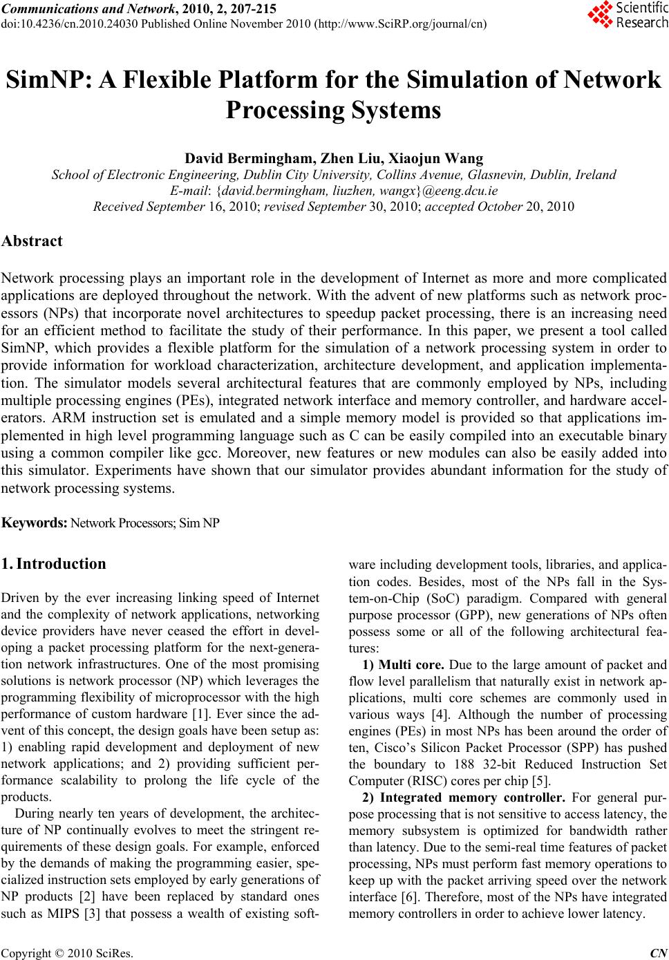 Communications and Network, 2010, 2, 207-215 doi:10.4236/cn.2010.24030 Published Online November 2010 (http://www.SciRP.org/journal/cn) Copyright © 2010 SciRes. CN SimNP: A Flexible Platform for the Simulation of Network Processing Systems David Bermingham, Zhen Liu, Xiaojun Wang School of Electronic Engineering, Dublin City University, Collins Avenu e, Glasnevin, Dublin, Ireland E-mail: {david.bermingham , liuzhen, wangx}@eeng.dcu.ie Received September 16, 2010; revised September 30, 2010; accepted October 20, 2010 Abstract Network processing plays an important role in the development of Internet as more and more complicated applications are deployed throughout the network. With the advent of new platforms such as network proc- essors (NPs) that incorporate novel architectures to speedup packet processing, there is an increasing need for an efficient method to facilitate the study of their performance. In this paper, we present a tool called SimNP, which provides a flexible platform for the simulation of a network processing system in order to provide information for workload characterization, architecture development, and application implementa- tion. The simulator models several architectural features that are commonly employed by NPs, including multiple processing engines (PEs), integrated network interface and memory controller, and hardware accel- erators. ARM instruction set is emulated and a simple memory model is provided so that applications im- plemented in high level programming language such as C can be easily compiled into an executable binary using a common compiler like gcc. Moreover, new features or new modules can also be easily added into this simulator. Experiments have shown that our simulator provides abundant information for the study of network processing systems. Keywords: Network Processors; Sim NP 1. Introduction Driven by the ever increasing linking speed of Internet and the complexity of network applications, networking device providers have never ceased the effort in devel- oping a packet processing platform for the next-genera- tion network infrastructures. One of the most promising solutions is network processor (NP) which leverages the programming flexibility of microprocessor with the high performance of custom hardware [1]. Ever since the ad- vent of this concept, the design goals have been setup as: 1) enabling rapid development and deployment of new network applications; and 2) providing sufficient per- formance scalability to prolong the life cycle of the products. During nearly ten years of development, the architec- ture of NP continually evolves to meet the stringent re- quirements of these design goals. For example, enforced by the demands of making the programming easier, spe- cialized instruction sets employed by early generations of NP products [2] have been replaced by standard ones such as MIPS [3] that possess a wealth of existing soft- ware including development tools, libraries, and applica- tion codes. Besides, most of the NPs fall in the Sys- tem-on-Chip (SoC) paradigm. Compared with general purpose processor (GPP), new generations of NPs often possess some or all of the following architectural fea- tures: 1) Multi core. Due to the large amount of packet and flow level parallelism that naturally exist in network ap- plications, multi core schemes are commonly used in various ways [4]. Although the number of processing engines (PEs) in most NPs has been around the order of ten, Cisco’s Silicon Packet Processor (SPP) has pushed the boundary to 188 32-bit Reduced Instruction Set Computer (RISC) cores per chip [5]. 2) Integrated memory controller. For general pur- pose processing that is not sensitive to access latency, the memory subsystem is optimized for bandwidth rather than latency. Due to the semi-real time features of packet processing, NPs must perform fast memory operations to keep up with the packet arriving speed over the network interface [6]. Therefore, most of the NPs have integrated memory controllers in order to achieve lower latency. 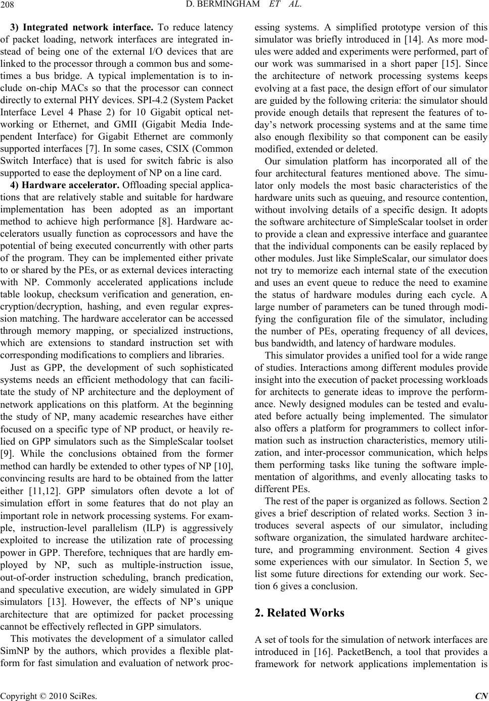 208 D. BERMINGHAM ET AL. 3) Integrated network interface. To reduce latency of packet loading, network interfaces are integrated in- stead of being one of the external I/O devices that are linked to the processor through a common bus and some- times a bus bridge. A typical implementation is to in- clude on-chip MACs so that the processor can connect directly to external PHY devices. SPI-4.2 (System Packet Interface Level 4 Phase 2) for 10 Gigabit optical net- working or Ethernet, and GMII (Gigabit Media Inde- pendent Interface) for Gigabit Ethernet are commonly supported interfaces [7]. In some cases, CSIX (Common Switch Interface) that is used for switch fabric is also supported to ease the deployment of NP on a line card. 4) Hardware accelerator. Offloading special applica- tions that are relatively stable and suitable for hardware implementation has been adopted as an important method to achieve high performance [8]. Hardware ac- celerators usually function as coprocessors and have the potential of being executed concurrently with other parts of the program. They can be implemented either private to or shared by the PEs, or as external devices interacting with NP. Commonly accelerated applications include table lookup, checksum verification and generation, en- cryption/decryption, hashing, and even regular expres- sion matching. The hardware accelerator can be accessed through memory mapping, or specialized instructions, which are extensions to standard instruction set with corresponding modifications to compliers and libraries. Just as GPP, the development of such sophisticated systems needs an efficient methodology that can facili- tate the study of NP architecture and the deployment of network applications on this platform. At the beginning the study of NP, many academic researches have either focused on a specific type of NP product, or heavily re- lied on GPP simulators such as the SimpleScalar toolset [9]. While the conclusions obtained from the former method can hardly be extended to other types of NP [10], convincing results are hard to be obtained fro m the latter either [11,12]. GPP simulators often devote a lot of simulation effort in some features that do not play an important role in network processing systems. For exam- ple, instruction-level parallelism (ILP) is aggressively exploited to increase the utilization rate of processing power in GPP. Therefore, techniques that are hardly em- ployed by NP, such as multiple-instruction issue, out-of-order instruction scheduling, branch predication, and speculative execution, are widely simulated in GPP simulators [13]. However, the effects of NP’s unique architecture that are optimized for packet processing cannot be effectively reflected in GPP simulators. This motivates the development of a simulator called SimNP by the authors, which provides a flexible plat- form for fast simulation and evaluation of network proc- essing systems. A simplified prototype version of this simulator was briefly introduced in [14]. As more mod- ules were added and experiments were performed, part of our work was summarised in a short paper [15]. Since the architecture of network processing systems keeps evolving at a fast pace, the design effort of our simulator are guided by the following criteria: the simulator sho uld provide enough details that represent the features of to- day’s network processing systems and at the same time also enough flexibility so that component can be easily modifi ed, extended or delet e d. Our simulation platform has incorporated all of the four architectural features mentioned above. The simu- lator only models the most basic characteristics of the hardware units such as queuing, and resource contention, without involving details of a specific design. It adopts the software architecture of SimpleScalar toolset in order to provide a clean and expressive interface and guarantee that the individual components can be easily replaced by other modules. Just like SimpleScalar, our simulator does not try to memorize each internal state of the execution and uses an event queue to reduce the need to examine the status of hardware modules during each cycle. A large number of parameters can be tuned through modi- fying the configuration file of the simulator, including the number of PEs, operating frequency of all devices, bus bandwidth, and latency of hardware modules. This simulator provides a unified tool for a wide range of studies. Interactions among different modules provide insight into th e execution of packet processing workloads for architects to generate ideas to improve the perform- ance. Newly designed modules can be tested and evalu- ated before actually being implemented. The simulator also offers a platform for programmers to collect infor- mation such as instruction characteristics, memory utili- zation, and inter-processor communication, which helps them performing tasks like tuning the software imple- mentation of algorithms, and evenly allocating tasks to different PEs. The rest of the paper is organized as follows. Section 2 gives a brief description of related works. Section 3 in- troduces several aspects of our simulator, including software organization, the simulated hardware architec- ture, and programming environment. Section 4 gives some experiences with our simulator. In Section 5, we list some future directions for extending our work. Sec- tion 6 gives a conclusion. 2. Related Works A set of tools for the simulation of network interfaces are introduced in [16]. PacketBench, a tool that provides a framework for network applications implementation is Copyright © 2010 SciRes. CN  D. BERMINGHAM ET AL. 209 presented in [17]. This tool only adds several APIs for loading packets into SimpleScalar and omits most of the impact of NP architectural features. Simulators targeted to real life network processors are also developed. Yan Luo et al have developed a NP simulator called NePSim that complies with most of the functionalities described in Intel IXP1200 specification [18]. Compared with IXP1200’s own cycle-accurate architectural simulator, NePSim estimates the packet throughpu t with an average of only 1% of error and the processing time with 6% of error on the tested benchmark applications. However, application development on IXP1200 requires a thorough understanding of the underlying hardware details. The difficulty in programming has greatly constrained the usage of NePSim in any architectural studies. In [19], Deepak Suryanarayanan et al. present a component net- work simulator called ComNetSim which models a Cisco Toaster network processor. However, it only provides functional simulation and is implemented according to the execution of applications that are modeled. 3. The SimNP Platform The SimNP derives its software architecture from the widely used SimpleScalar/ARM toolset, which allows us to perform accurate simulation of modules such as de- vice command queues and bus arbitration using the exe- cution-driven method. Our simulation platform organizes the simulated hardware components to p ermit their reuse over a wide range of modeling tasks. It consists of sev- eral interchangeable modules to model a range of archi- tectural features. It can be used to model the entire life cycle of packet processing, from packet receiving to its transmission onto the external link. Although it models the architecture of a typical network processor, its usage can be easily extended to other network processing sys- tems. Most of the packet processing is based on software implementation , in addition to the support for simulatin g hardware accelerators. 3.1. Software Architecture The simulator follows the traditional way of having a front-end functional simulator that interprets instructions and handles I/O operations, and a back-end performance model that calculates the expected behaviors according to the executed instructions. To maintain compatibility, the execution of system calls still depends on calling the host operating system. For the simulated packet interface, we provide a specific programming paradigm to avoid using system calls. The simulator accepts instruction binaries and packet traces as input. For applications that need table accesses, a memory image file of these tables should be loaded before the program executes. Both real-life packet traces and synthesized traffic can be used within simulations. In the case of packet headers collected from a website such as the National Laboratory for Applied Network Re- search (NLANR), any encoding format (TSH, TCPDUMP, ERF, FR+) can be used [20]. A dedicated trace loader is able to turn each of them into the SimNP native packet format, with anonymous IP addresses be- ing replaced with random IP addresses generated from real-life route table or rule-set, and payload being padded with random contents to the length indicated in packet header. 3.2. Simulated Hardware Architecture As has mentioned before, the design choices of the simulator concentrate on selecting only those necessary features of packet processing so that the simulated archi- tecture can represent a wide range of network processing systems without getting involved into too many specific details. As shown in Figure 1, all of the four architec- tural features described in Section 1 have been covered in our simulator. As the advance of NP architecture and software, new features are expected to be easily added. 3.2.1. Processing En gi nes SimNP supports up to 32 PEs, with each PE functionally emulating the ARM Instruction Set. The ARM instruc- tion set is chosen for two reasons. Firstly, the Instruction Set Architecture (ISA) provided by the ARM processor closely resembles the small RISC type PEs used with in a NP, and secondly, the maturity of the ARM architecture provides a number of efficient compiler solutions. With free compiler suites such as gcc [21] allowing fast gen- eration of ARM code from languages such as C, and C++. The processing cores support the ARM7 integer instruction set and FPA floating-point extensions, with- out the 16-bit thumb extension. Each PE also has a Control Store, Local SRAM and Local Hardware Accelerators, as will be explained later. The communications between PEs and other devices are performed through a System Bus. Since a shared bus system can result in long access latencies to both I/O and memory, PEs are simulated with an automatic suspen- sion mechanism once a command has been issued. When the command has been completed, the PE resumes from its previous state. At current stage we do not implement synchronization mechanism. 3.2.2. Memory Subsystem Qshared by all PEs. The operation parameters, such as ccess latency and number of banks in DRAM, of these a Copyright © 2010 SciRes. CN  D. BERMINGHAM ET AL. Copyright © 2010 SciRes. CN 210 ... System Bus Rx Buffer Bus Interface Shared Hardware Accelerators ARM Register File Local SRAM Processing Engine Control Store Local Hardware Accelerators ARM Register File Local SRAM Processing Engine Control Store Local Hardware Accelerators Bus Interface SRAM SRAM Bus Interf ace Bus Inter face DMA Tx Buffer I/F CTRL DRAM Controller Bus Interface DRAM TCAM Controller Local Masks TCAM SRAM Controller Bus Interface SRAM Cluster ACluster B Figure 1. Hardware architecture. memory devices are configurable. Prefix Matching (LPM) applications such as route table lookup. In addition to normal content, both global mask (GM) and local masks are needed to be loaded from- memory image before the processing begins. Both Control Store and Local SRAM provide single cycle access. As shown in Figure 2, they can be used to store the program execution environment for each PE, including instructions, initialized and uninitialized data, stack, heap, and arguments. Packets are normally loaded from network interface into DRAM, along with the queuing information stored in global SRAM. Other shared data structures such as routing table, packet clas- sification rule sets, can be stored in either global SRAM or DRAM. TCAM is expected to accelerate the Longest Figure 2 also shows a possible PE memory map. The address space [0000 0000h, 0FFF FFFFh] is private to each PE, while the address space from 1000 0000h is shared among all PEs. Unlike Intel IXP instructions, ARM uses the same instructions to access different type of memory devices. The device-to-address mapping is implemented by modifying the parameters for compiler and specifying starting address in memory image. With- out changing the ARM instructions, it is easier and more flexible for the programmer to create new applications. 3.2.3. Netw ork Interface The SimNP network interface is designed to model the behavior of SPI-like interface. To simplify the program- ming of network applications, packets are maintained in a link-list, instead of fixed-length blocks as in some real-life NPs, when stored in the memory pool of net- work interface. Once the Rx Buffer has been filled, newly arrived packets are dropped. Similarly, a full Tx Buffer blocks the processing of some PEs until enough space is released. PEs demand packet from Rx Buffer or write packet to Tx Buffer by issuing commands to net- work interface. The actual transfers between network interface and memory are handled via a DMA controller which uses either main system bus or a dedicated bus (not shown in Figure 1. A dedicated bus is provided to reduce the contention on system bus, since the traffic volume generated by parallel architecture can be poten- tially very high. Figure 2. An example of memory usage and PE address space mapping. 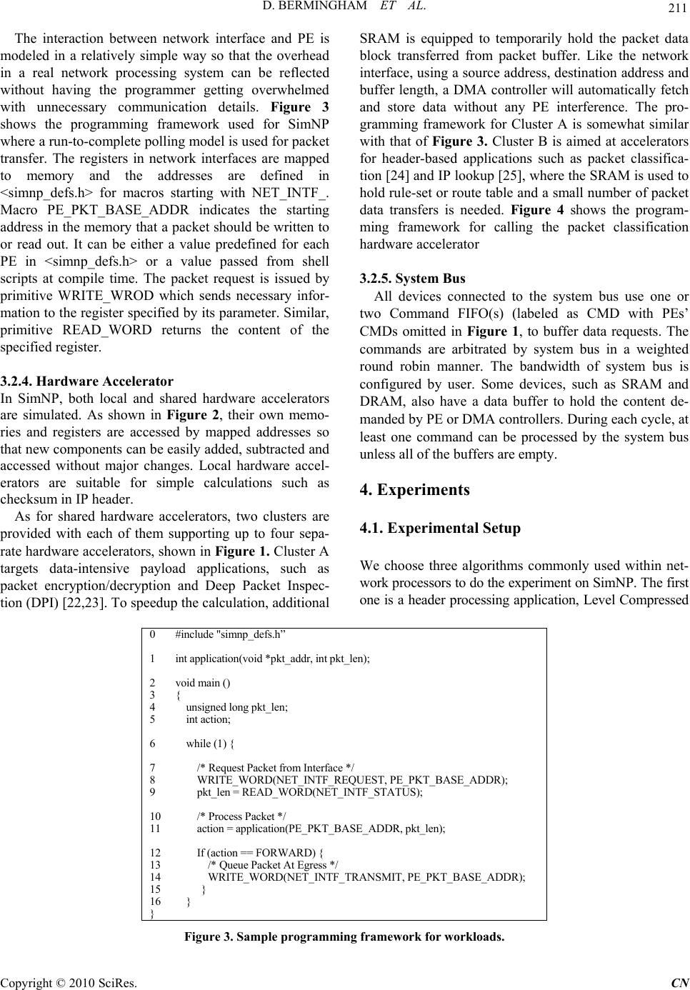 D. BERMINGHAM ET AL. 211 The interaction between network interface and PE is modeled in a relatively simple way so that the overhead in a real network processing system can be reflected without having the programmer getting overwhelmed with unnecessary communication details. Figure 3 shows the programming framework used for SimNP where a run-to-complete polling model is used for packet transfer. The registers in network interfaces are mapped to memory and the addresses are defined in <simnp_defs.h> for macros starting with NET_INTF_. Macro PE_PKT_BASE_ADDR indicates the starting address in the memory that a packet shou ld be written to or read out. It can be either a value predefined for each PE in <simnp_defs.h> or a value passed from shell scripts at compile time. The packet request is issued by primitive WRITE_WROD which sends necessary infor- mation to the register specified by its parameter. Similar, primitive READ_WORD returns the content of the specified register. 3.2.4. Hardware Accelerator In SimNP, both local and shared hardware accelerators are simulated. As shown in Figure 2, their own memo- ries and registers are accessed by mapped addresses so that new components can be easily added, subtracted and accessed without major changes. Local hardware accel- erators are suitable for simple calculations such as checksum in IP header. As for shared hardware accelerators, two clusters are provided with each of them supporting up to four sepa- rate hardware accelerators, shown in Figure 1. Cluster A targets data-intensive payload applications, such as packet encryption/decryption and Deep Packet Inspec- tion (DPI) [22,23]. To speedup the calculation, additional SRAM is equipped to temporarily hold the packet data block transferred from packet buffer. Like the network interface, using a sour ce address, destination address and buffer length, a DMA controller will automatically fetch and store data without any PE interference. The pro- gramming framework for Cluster A is somewhat similar with that of Figure 3. Cluster B is aimed at accelerators for header-based applications such as packet classifica- tion [24] and IP lookup [25], where the SRAM is used to hold rule-set or route table and a small number of packet data transfers is needed. Figure 4 shows the program- ming framework for calling the packet classification hardware accelerator 3.2.5. System Bus All devices connected to the system bus use one or two Command FIFO(s) (labeled as CMD with PEs’ CMDs omitted in Figure 1, to buffer data requests. The commands are arbitrated by system bus in a weighted round robin manner. The bandwidth of system bus is configured by user. Some devices, such as SRAM and DRAM, also have a data buffer to hold the content de- manded by PE or DMA controllers. During each cycle, at least one command can be processed by the system bus unless all of the buffers are empty. 4. Experiments 4.1. Experimental Setup We choose three algorithms commonly used within net- work processors to do the experiment on SimNP. The first one is a header processing application, Level Compressed 0 #include "simnp_defs.h” 1 int application(void *pkt_addr, int pkt_len); 2 void main () 3 { 4 unsigned long pkt_len; 5 int action; 6 while (1) { 7 /* Request Packet from Interface */ 8 WRITE_WORD(NET_INTF_REQUEST, PE_PKT_BASE_ADDR); 9 pkt_len = READ_WORD(NET_INTF_STATUS); 10 /* Process Packet */ 11 action = application(PE_PKT_BASE_ADDR, pkt_len); 12 If (action == FORWARD) { 13 /* Queue Packet At Egress */ 14 WRITE_WORD(NET_INTF_TRANSMIT, PE_PKT_BASE_ADDR); 15 } 16 } } Figure 3. Sample programming framework for workloads. Copyright © 2010 SciRes. CN 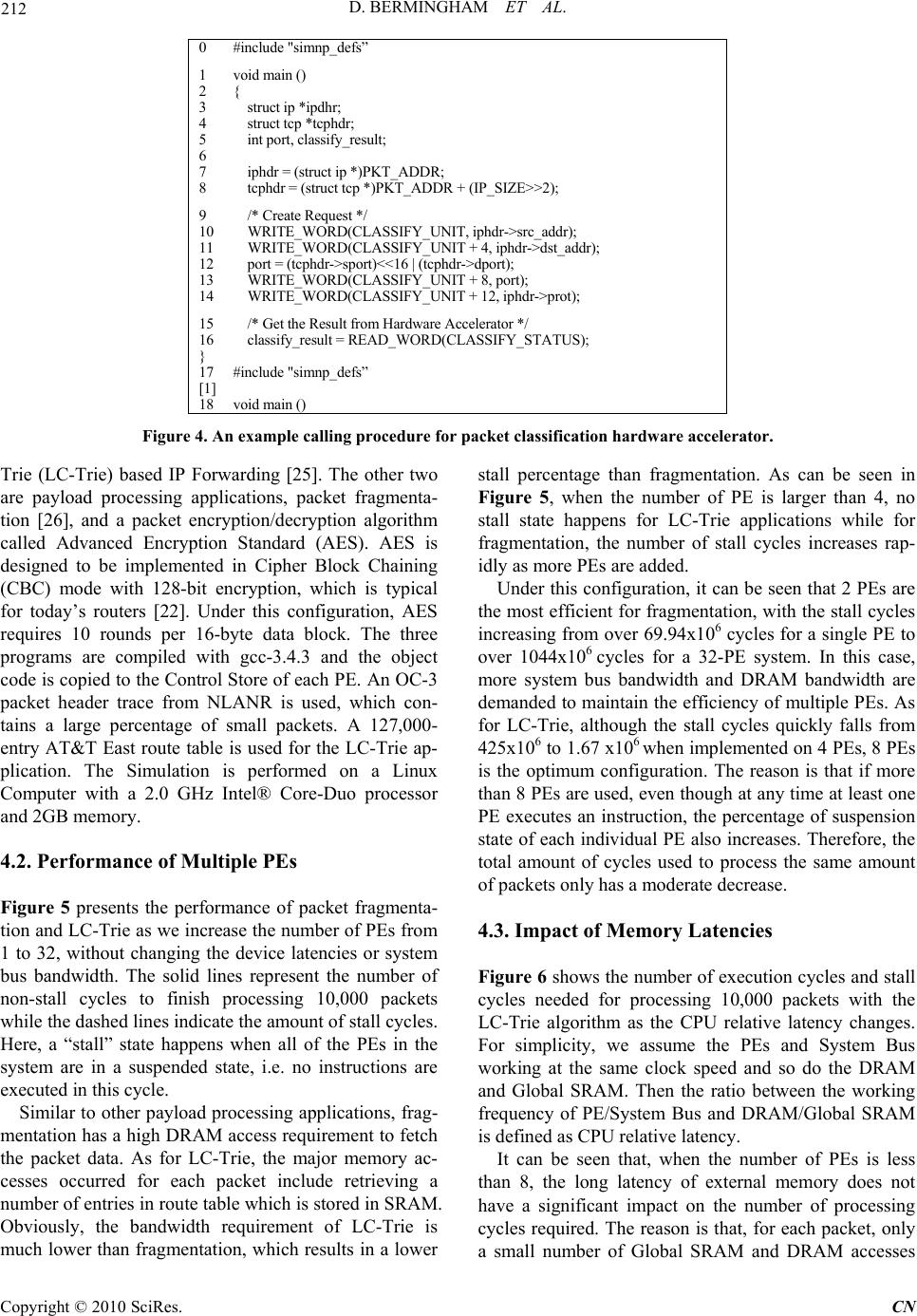 212 D. BERMINGHAM ET AL. 0 #include "simnp_defs” 1 void main () 2 { 3 struct ip *ipdhr; 4 struct tcp *tcphdr; 5 int port, classify_result; 6 7 iphdr = (struct ip *)PKT_ADDR; 8 tcphdr = (str uct tcp *)PKT_ADDR + (IP_SIZE>>2); 9 /* Create Request */ 10 WRITE_WORD(CLASSIFY_UNIT, iphdr->src_addr); 11 WRITE_WORD(CLASSIFY_UNIT + 4, iphdr->dst_addr); 12 port = (tcphdr->sport)<<16 | ( tcphdr->dport); 13 WRITE_WORD(CLASSIFY_UNIT + 8, port); 14 WRITE_WORD(CL ASSIFY_UNIT + 12, iphdr->prot) ; 15 /* Get the Result fr om Hardwar e Acceler ator */ 16 classify_result = READ_WORD(CLASSIFY_STATUS); } 17 #include "simnp_defs” [1] 18 void main () Figure 4. An example calling procedure for packet classification hardware accelerator. Trie (LC-Trie) based IP Forwarding [25]. The other two are payload processing applications, packet fragmenta- tion [26], and a packet encryption/decryption algorithm called Advanced Encryption Standard (AES). AES is designed to be implemented in Cipher Block Chaining (CBC) mode with 128-bit encryption, which is typical for today’s routers [22]. Under this configuration, AES requires 10 rounds per 16-byte data block. The three programs are compiled with gcc-3.4.3 and the object code is copied to the Control Store of each PE. An OC-3 packet header trace from NLANR is used, which con- tains a large percentage of small packets. A 127,000- entry AT&T East route table is used for the LC-Trie ap- plication. The Simulation is performed on a Linux Computer with a 2.0 GHz Intel® Core-Duo processor and 2GB memory. 4.2. Performance of Multiple PEs Figure 5 presents the performance of packet fragmenta- tion and LC-Trie as we increase the number of PEs from 1 to 32, without changing the device latencies or system bus bandwidth. The solid lines represent the number of non-stall cycles to finish processing 10,000 packets while the dashed lines indicate the amount of stall cycles. Here, a “stall” state happens when all of the PEs in the system are in a suspended state, i.e. no instructions are executed in this cycle. Similar to other payload processing applications, frag- mentation has a high DRAM access requirement to fetch the packet data. As for LC-Trie, the major memory ac- cesses occurred for each packet include retrieving a number of entries in route table wh ich is stored in SRAM. Obviously, the bandwidth requirement of LC-Trie is much lower than fragmentation, which results in a lower stall percentage than fragmentation. As can be seen in Figure 5, when the number of PE is larger than 4, no stall state happens for LC-Trie applications while for fragmentation, the number of stall cycles increases rap- idly as more PEs are added. Under this configuration, it can be seen that 2 PEs are the most efficient for fragmentation, with the stall cycles increasing from over 69.94x10⁶ cycles for a single PE to over 1044x106 cycles for a 32-PE system. In this case, more system bus bandwidth and DRAM bandwidth are demanded to maintain the efficiency of multiple PEs. As for LC-Trie, although the stall cycles quickly falls from 425x106 to 1 .67 x106 wh en implemented on 4 PEs, 8 PEs is the optimum configuration. The reason is that if more than 8 PEs are used, even though at any time at least one PE executes an instruction, the percentage of suspension state of each individual PE also increases. Therefore, the total amount of cycles used to process the same amount of packets only has a moderate decrease. 4.3. Impact of Memory Latencies Figure 6 shows the number of execution cycles and stall cycles needed for processing 10,000 packets with the LC-Trie algorithm as the CPU relative latency changes. For simplicity, we assume the PEs and System Bus working at the same clock speed and so do the DRAM and Global SRAM. Then the ratio between the working frequency of PE/System Bus and DRAM/Global SRAM is defined as CPU relative latency. It can be seen that, when the number of PEs is less than 8, the long latency of external memory does not have a significant impact on the number of processing cycles required. The reason is that, for each packet, only a small number of Global SRAM and DRAM accesses Copyright © 2010 SciRes. CN 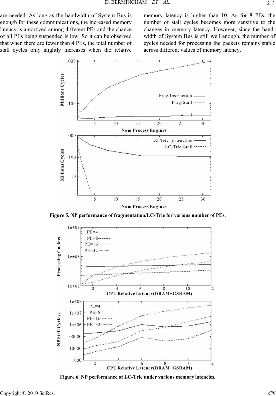 D. BERMINGHAM ET AL. 213 are needed. As long as the bandwidth of System Bus is enough for these communications, the increased memory latency is amortized among different PEs and the chance of all PEs being suspended is low. So it can be observed that when there are fewer than 4 PEs, the total number of stall cycles only slightly increases when the relative memory latency is higher than 10. As for 8 PEs, the number of stall cycles becomes more sensitive to the changes in memory latency. However, since the band- width of System Bus is still well enough, the number of cycles needed for processing the packets remains stable across different values of memory latency. Figure 5. NP performance of fragmentation/LC-Trie for various number of PEs. Figure 6. NP performance of LC-Trie under various memory latencies. Copyright © 2010 SciRes. CN 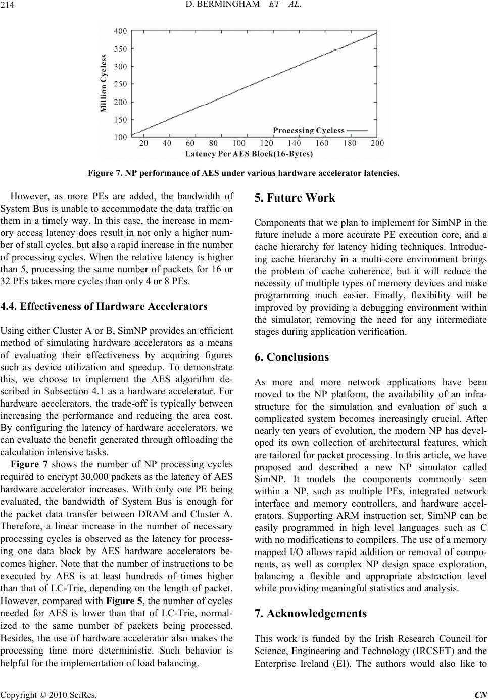 214 D. BERMINGHAM ET AL. Figure 7. NP performance of AES under various hardware accelerator latencies. However, as more PEs are added, the bandwidth of System Bus is unable to accommodate the data traffic on them in a timely way. In this case, the increase in mem- ory access latency does result in not only a higher num- ber of stall cycles, but also a rapid increase in the number of processing cycles. When the relative latency is higher than 5, processing the same number of packets for 16 or 32 PEs takes more cycles than only 4 or 8 PEs. 4.4. Effectiveness of Hardware Accelerators Using either Cluster A or B, SimNP provides an efficient method of simulating hardware accelerators as a means of evaluating their effectiveness by acquiring figures such as device utilization and speedup. To demonstrate this, we choose to implement the AES algorithm de- scribed in Subsection 4.1 as a hardware accelerator. For hardware accelerators, the trade-off is typically between increasing the performance and reducing the area cost. By configuring the latency of hardware accelerators, we can evaluate the benefit generated through offloading the calculation intensiv e tasks. Figure 7 shows the number of NP processing cycles required to en crypt 30,000 packets as the laten cy of AES hardware accelerator increases. With only one PE being evaluated, the bandwidth of System Bus is enough for the packet data transfer between DRAM and Cluster A. Therefore, a linear increase in the number of necessary processing cycles is observed as the latency for process- ing one data block by AES hardware accelerators be- comes higher. Note that the number of instructions to be executed by AES is at least hundreds of times higher than that of LC-Trie, depending on the length of packet. However, compared with Figure 5, the number of cycles needed for AES is lower than that of LC-Trie, normal- ized to the same number of packets being processed. Besides, the use of hardware accelerator also makes the processing time more deterministic. Such behavior is helpful for the implementation of load balancing. 5. Future Work Components that we plan to implement for SimNP in the future include a more accurate PE execution core, and a cache hierarchy for latency hiding techniques. Introduc- ing cache hierarchy in a multi-core environment brings the problem of cache coherence, but it will reduce the necessity of multiple type s of memory dev ices and make programming much easier. Finally, flexibility will be improved by providing a debugging environment within the simulator, removing the need for any intermediate stages during a ppl i cation verificat i o n. 6. Conclusions As more and more network applications have been moved to the NP platform, the availability of an infra- structure for the simulation and evaluation of such a complicated system becomes increasingly crucial. After nearly ten years of evolution, the modern NP has devel- oped its own collection of architectural features, which are tailored for packet processing. In this article, we have proposed and described a new NP simulator called SimNP. It models the components commonly seen within a NP, such as multiple PEs, integrated network interface and memory controllers, and hardware accel- erators. Supporting ARM instruction set, SimNP can be easily programmed in high level languages such as C with no modifications to compilers. The use of a memory mapped I/O allows rapid addition or removal of compo- nents, as well as complex NP design space exploration, balancing a flexible and appropriate abstraction level while providing meaningful statistics and analysis. 7. Acknowledgements This work is funded by the Irish Research Council for Science, Engineering and Technology (IRCSET) and the Enterprise Ireland (EI). The authors would also like to Copyright © 2010 SciRes. CN  D. BERMINGHAM ET AL. 215 thank Ms. Yachao Zhou and Mr. Feng Guo for their work in preparing this manuscript. 8. References [1] D. Comer and L. Peterson, “Network Systems Design Using Network Processors,” 1st Edition, Prentice-Hall, Inc., USA, 2003. [2] Intel Inc., IXP2800 Hardware Reference Manual. [3] M. R. Hussain, “Octeon Multi-Core Processor,” Keynote Speech of ANCS 2006, San Jose, California, USA, De- cember 2006. [4] M. Venkatachalam, P. Chandra and R. Yavatkar, “A Highly Flexible, Distributed Multiprocessor Architecture for Network Processing,” Computer Networks, Vol. 41, No. 5, 2003, pp. 563-586. [5] W. Eatherton, “The Push of Network Processing to the Top of the Pyramid,” Keynote Address at the Symposium on Architectures for Networking and Communication Systems (ANCS2005), Princeton, New Jersey, USA, Oc- tober 2005. [6] J. Mudigonda, H. M. Vin and R. Yavatkar, “Managing Memory Access Latency in Packet Processing,” Pro- ceedings of the International Conference on Measure- ment and Modeling of Computer Systems (SIGMETRICS 2005), Banff, Alberta, Canada, June 2005, pp. 396-397 [7] M. Peyravian and J. Calvignac, “Fundamental Architec- ture Considerations for Network Processors,” Computer Networks, Vol. 41, No. 5, 2003, pp. 587-600. [8] W. Bux, W. E. Denzel, T. Engbersen, A. Herkersdorf and R.P. Luijten, “Technologies and Building Blocks for Fast Packet Forwarding,” IEEE Communications Magazine, , Vol. 39, No. 1, 2001, pp. 70-77 [9] D. Burger and T. Austin, “The SimpleScalar tool set ver- stion 2.0,” Computer Architecture News, Vol. 25, No. 3, 1997, pp.13-25 [10] N. Shah, W. Plishker and K. Keutzer, “NP-click: A pro- ductive software development approach for network processors,” IEEE Micro, Vol. 24, No. 5, 2004, pp. 45-54. [11] T. Wolf and M. Franklin, “Commbench: A Telecommu- nications Benchmark for Network Processors,” IEEE In- ternational Symposium on Performance Analysis of Sys- tems and Software, Austin, USA, April 2000. [12] G. Memik, W. H. Mangione-Smith and W. Hu, “NetBench: A Benchmarking Suite for Network Proces- sors,” Proceedings of IEEE/ACM International Confer- ence on Computer-Aided Design, Digest of Technical Papers, San Jose, USA, November 2001, pp. 39-42. [13] J. L. Hennessy and D. A. Patterson, “Computer Architec- ture: A Quantitative Approach,” 4th Edition, Morgan Kaufmann, USA, 2006. [14] Z. Liu, D. Bermingham and X. Wang, “Towards Fast and Flexible Simulation of Network Processors,” The IET 2008 China-Ireland International Conference on Infor- mation and Communications Technologies (CIICT2008), Beijing, China, September 2008, pp. 611-614. [15] D. Bermingham, Z. Liu and X. Wang, “SimNP: A Flexi- ble Platform for the Simulation of Network Processing System,” ACM/IEEE Symposium on Architectures for Networking and Communications Systems (ANCS2008), California, USA, November 2008, pp. 123-124. [16] P. Willman, M. Broglioli and V. Pai, “Spinach: A Lib- erty-Based Simulator for Programmable Network Inter- face Architectures,” LCTES, 2004, pp. 20-29. [17] R. Ramaswamy and T. Wolf, “PacketBench: A Tool for Workload Characterization of Network Processing,” Pro- ceeding of IEEE 6th Annual Workshop on Workload Characterization (WWC-6), Austin, TX, 2003, pp. 42-50. [18] Y. Luo, J. Yang, L. N. Bhuyan and L. Zhao, “NePSim: A Network Processor Simulator with a Power Evaluation Framework,” IEEE Micro, Vol. 24, No. 5, 2004, pp. 34- 44. [19] D. Suryanarayanan, J. Marshall and G. T. Byrd, “A Meth- odology and Simulator for the Study of Network Proces- sors,” In: P. Crowley, M. A. Franklin, H. Hadimioglu, and P. Z. Onufryk, Eds., Network Processor Design: Is- sues and Practices, Morgan Kaufmann Publishers, USA, 2003, pp. 27-54. [20] “NLANR Passive Measurement Analysis,” 2007. http:// pma. nlanr.net/ [21] “The GNU Compiler Collection,” 2009. http://gcc.gnu.org [22] B. Schneier, “Applied Cryptography,” 2nd Edition, John Wiley & Sons, New York, 1996. [23] S. Kumar, J. Turner and J. Williams, “Advanced Algo- rithms for Fast and Scalable Deep Packet Inspection,” Proceedings of the ACM/IEEE symposium on Architec- ture for networking and communications systems, San Jose, USA, December 2006, pp. 81-92. [24] P. Gupta and N. McKeown, “Packet Classification on Multiple Fields,” Proceedings of the 1999 Conference on Applications, Technologies, Architectures and Protocols for Computer Communications (ACM SIGCOMM’99), Massachusetts, US, September 1999, pp. 147-160. [25] S. Nilsson and G. Karlsson, “IP-Address Lookup Using LC-Tries,” IEEE Journal on Selected Areas in Commu- nications, Vol. 17, No. 6, June 1999, pp. 1083-1092. [26] RFC-791, “Internet Protocol DARPA Internet Pro- gram Protocol Specification,” 1981. Copyright © 2010 SciRes. CN |