Circuits and Systems
Vol.07 No.09(2016), Article ID:68862,15 pages
10.4236/cs.2016.79212
Design and Implementation of ANFIS Controller Based Grid Connected Voltage Source Inverters in RTOS Environment
D. Thalapathi Udhayakumar1, P. S. Manoharan2
1Department of Electrical and Electronics Engineering, Christian College of Engineering and Technology, Oddanchtram, Dindigul, Tamil Nadu, India
2Department of Electrical and Electronics Engineering, Thiagarajar College of Engineering, Madurai, Tamil Nadu, India

Copyright © 2016 by authors and Scientific Research Publishing Inc.
This work is licensed under the Creative Commons Attribution International License (CC BY).
http://creativecommons.org/licenses/by/4.0/


Received 9 April 2016; accepted 18 April 2016; published 22 July 2016
ABSTRACT
In this manuscript it is proposed and demonstrated that how an ANFIS (Adaptive Neuro Fuzzy Inference System) can be used in the control of a Voltage Source Inverter (VSI) connected to the grid. Volatile changes in the gird parameters rising by its variable demands and other related issues may humiliate the efficiency with which power can be injected into the grid. The system becomes a higher order one with the filters used at the terminal of the Voltage Source Inverter (VSI) along with the parameters of the grid which change from time to time. Single time tuned mathematical controllers like the PID variants are not suitable for such applications. Considering the increased order of the system and the associated non-linearity we have to look out for intelligent controllers. An ANFIS based control is found to be promising; the development and implementation of one such are demonstrated in this paper using the MATLAB SIMULINK platform and through experimental verification using the Reduced Instruction Set Computer (RISC) Microcontroller Advanced RISC Machine (ARM) processor as the central controller for the VSI.
Keywords:
ANFIS Controller, Power Electronics, Voltage Source Inverter

1. Introduction
This is the age of distributed generation, generating here and there something, using the locally available natural resource like wind, sun light or a water fall and so on. These natural resources are preferred for the generation of electricity because they offer almost free of cost whatever they offer big or small one. Clean production methodologies are involved because of no burring and no smoke and as such these methods are eco-friendly. They also help in stabilising the global warming by at least not increasing it.
Usually after many stages of power conversion like DC to DC or AC to DC, buck boost stages etc. in the final stage of these non-conventional energy production we use voltage source inverters. It is the output of the VSI that will be ultimately connected to the grid. In the VSI we have two parameters at our disposal. They are the Modulation Index (MI) and the Theta of the reference signal. Now these two ultimate manipulated parameters are to be handled properly. These two parameters are manipulated based on the present situation of the distributed generation side and the parameters of the grid side.
Hectic research is ongoing in this area and there has been an amount of breakthrough as well happening in this area.
The authors in [1] have proposed a PI control system that can be used in this situation and it is the simplest of the control schemes; however it needs a thorough knowledge of the plant under consideration and the mathematical models involved. However this method is not robust, considering the real time parametric variations.
In [2] the authors have suggested a PI control scheme with two different filter models: one with an L alone model and another with the LCL model of the terminal filter. Though the system works well it is quite cumbersome considering the mathematical procedures involved.
At this junction, it can be observed that the use of power electronic converters in power generation and compensation schemes are not actually used at large in the power industry especially in our country because of the mathematical complicities associated with such types of control schemes, as it is quite difficult to comprehend and implement such schemes.
In [3] the authors have developed a fuzzy logic based control scheme. Well, it is an interesting idea to go ahead with the FLC but when actually implemented in a digital processor it is comparatively slow because of the procedures involved in the FLC especially if a large set of rules, derived from large segments of the universe of discourse, are used. In nonlinear plant models the difficulty arises in selecting the membership functions for each of the segment.
Artificial neural networks are also one among the fore runners and in [4] the authors have used ANN based control scheme. However there is no suggestion regarding the implementation of the same in a real time environment.
The Hα control has also been demonstrated in [5] ; it is applicable in unpredictably changing plant, parametric situations are well demonstrated and it proves to offer a robust control scheme. Again in this case also it is quite difficult to implement in real time hardware with commonly available micro controllers.
Therefore, considering the bottlenecks of the various control schemes previously discussed [6] - [34] , in this paper a novel control scheme, not involving hectic mathematical procedures, has been presented. The proposed methodology first develops an FLC, collect the relevant error, error rate and the output data and then train a neural network with this data. Once a suitable ANN is trained the ANN is implemented in Keil C and is down loaded into a micro controller. The encapsulated ANN embedded in the micro controller can now handle the situation and generate appropriate control quantities.
For this purpose we have used the MATLAB/SIMULINK environment for developing the simulation of the FLC and the ANN and then an LPC 2148 ARM processor in the experimental verification.
The chapters of this paper are arranged in the following manner. Next to the introduction part the general control principles of the VSI are outlined in Chapter 2. Chapter 3 discusses the fuzzy logic control and its ANN implementation. Chapter 4 discusses about the experimental verification. MATLAB/SIMULINK sub systems and the details of experimental verifications along with a discussion on the results are presented in Chapter 5 followed by the conclusion.
2. General Control Principles of the VSI
2.1. An Outline of the Three-Leg VSI
A voltage source inverter is one which generates a pre set voltage level across its terminals. The metrics of the output voltage of the VSI typically voltage amplitude, frequency and phase are usually, or at least expected to be, not altered according to the load connected across the terminals of the VSI.
There are two controls or three degrees of freedom associated with the three leg three phase voltage source inverter. These three are the modulation index, the phase angle phi and the frequency. These three factors are embedded, according to the power transaction and power quality requirement, in a signal called the reference signal which will be used in the PWM section. The output of the inverter, driven by the PWM pulses, exhibits the requirements as embedded in the reference signal and thus the actual requirement is fulfilled. Figure 1 shown gives the block schematic of the arrangement usually used to connect a three phase voltage source inverter to the grid.
2.2. The Control Techniques of the VSI
The three leg Voltage Source Inverter used in this application is of the Graetz bridge type. The three leg inverter is usually driven by any one of the popular PWM techniques like Sinusoidal PWM, the Space Vector PWM or the SHE PWM. While the carrier based SPWM and the mathematically derived SVPWM are high switching frequency cases and exhibit higher switching losses, the SHE PWM technique leads to elimination of selected harmonics while offering much reduced switching losses. Whatever is the PWM technique used the more important is the generation of the reference signal. The three phase reference signal necessary for the generation of the PWM pulses is generated using a number of techniques based on the constraints of power transaction required. There are two degrees of freedom. We can observe and control the Modulation Index or the Theta. Based on the real and reactive power requirements at the minimal THD levels with uniform voltage profile we have to make decisions regarding the MI and the Theta.
There are two controllers one for the generation of the MI and the other for the generation of the Theta. Any control scheme like the PID, FLC, H∞, or any Artificial Neural Network based controllers can do the job. While each of these methodologies can offer an acceptable control scenario some are better than the other in terms of the performance parameters.
The basic control scheme for the VSI in the context of injection of real and reactive power into the grid is shown in Figure 2.
2.3. Reactive Power Transaction
Consider two nodes A and B, linked by a reactor, between which we need reactive power transaction. As for reactive power transaction between the two nodes A and B connected by the reactor X it is required that the voltage at node A be higher in amplitude than that at node B such that reactive power can flow from node A to B

Figure 1. Block diagram of three phase voltage source inverter to the grid.
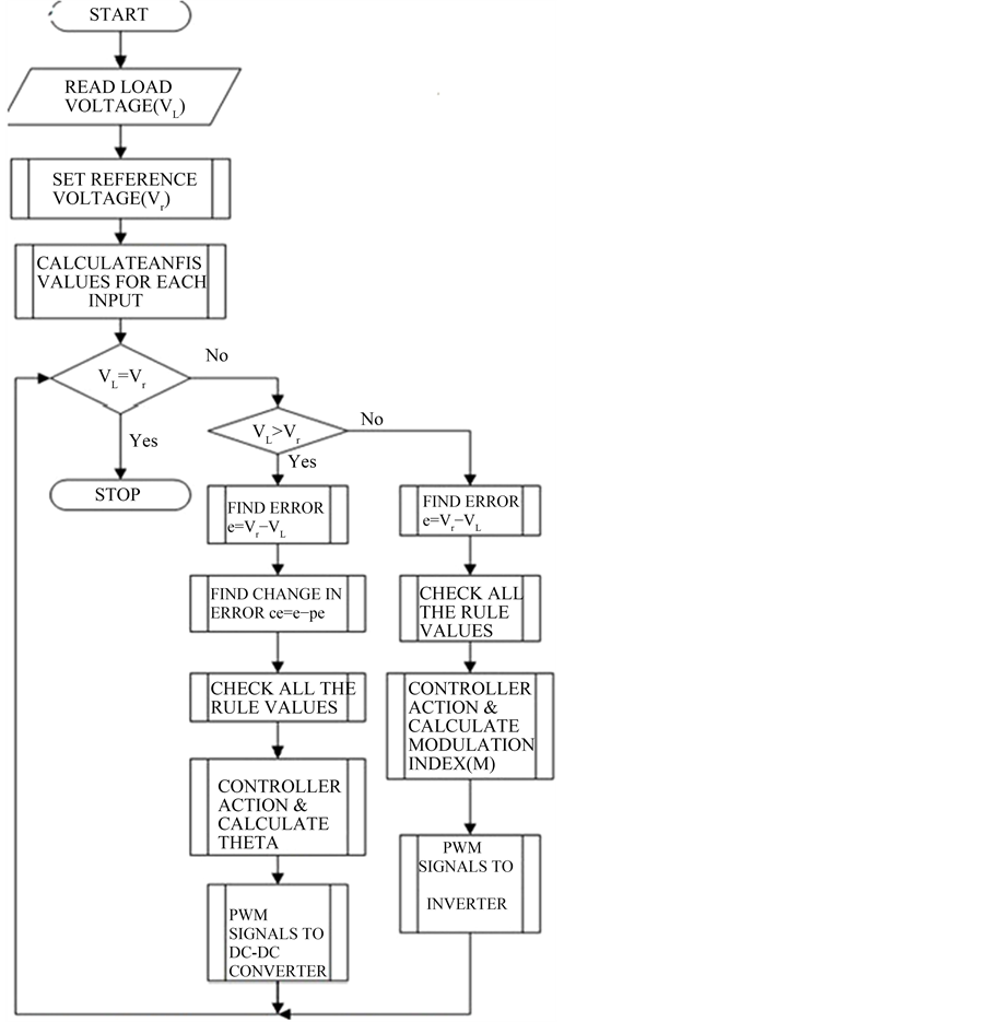
Figure 2. Basic control scheme of three phase voltage source inverter to the grid.
and vice versa.
This happens according to the Equation (1).
 (1)
(1)
where V1 and V2 are the two nodal voltages and X being the reactance between them then if the two nodal voltages are in phase, then Cosδ becomes equal to Cos0 = 1 and for the given potential difference between V1 and V2 the reactive power transact with the help of two controllers.
2.4. Real Power Transaction
The DC side of the VSI carries a fixed capacitor and this capacitor across the DC source and it to be held at a constant DC potential. This DC potential across the DC link capacitor is maintained by the control scheme of the VSI. For this purpose a control scheme is used in association real power transaction in the process of maintaining the required DC voltage across the DC link capacitor.
The real power transaction between the PCC and the DC link capacitor happens through the VSI and its operation is governed by the following equation.
 (2)
(2)
Real power transaction between two nodes at voltages V1 and V2 and linked by a reactor X is maximized when the phase angle V1 and V2 is 90 degrees. With 90 degrees phase difference between V1 and V2, the factor Sinδ in Equation (2) becomes Sin90 = 1.
Real power transaction between two nodes at voltages V1 and V2 and linked by a reactor X is maximized when the phase angle V1 and V2 is 90 degrees. With 90 degrees phase difference between V1 and V2, the factor Sinδ in Equation (2) becomes Sin90 = 1.
In this research the following methodology is sued.
Step 1. A set of FLCs are first developed.
Step 2. The FLC is first run and the real time data sets like error, error rate and the corresponding output for each of the controllers are collected in the MATLAB work space.
Step 3. Based on the collected data an ANFIS is trained and developed.
Step 4. The ANFIS is then used in the place of the previously used FLC and the model is run again to collect the data as done earlier in step 2.
Step 5. This data is further used to train a Back Propagation Feed Forward ANN unit.
Step 6. The newly formed ANN unit now replaces the ANFIS and the model is run again.
Step 7. Once satisfied with the performance of the latest ANN model which is a trained one the same is translated into a KEIL C program to be down loaded in the ARM 7 processor LPC 2148 and used in real time applications.
3. An Outline of Intelligent Controllers
3.1. Fuzzy Logic Control
Fuzzy logic control scheme is a technique to handle uncertain data in the process of arriving at an agreeable result. In any process control we are usually interested in the error and rate at which this error moves along with its direction so that an appropriate control action is carried out.
The error and the error rate are spread over a scale with a maximum and a minimum values. This scale is divided into a number of segments each segment occupying a certain range overlapping to a certain extent with the range of the adjacent segment. Over each such segment is the membership function. The membership function dictates the degree of membership of the error or error rate in that segment and we call this the Degree of Belief (DOB). The DOBs of error and error rate in real time are taken to a rule matrix and the appropriate rule is selected. This rule will decide what to do corresponding
Fuzzy logic, unlike the other systems of control does not make use of the numerical data instead it uses the linguistic variables. The MATLAB/SIMULINK tool was used in this research to develop the FLC and the ANFIS. The Figure 3 shows the block diagram of the control scheme as used in this research. The synchronously rotating frame was considered and the DQ quantities of the voltage at the point of common coupling the current injected into the grid to the currently prevailing situation.
3.2. Hybrid Soft Control Techniques
Hybrid software control schemes are used nowadays for getting the advantages of two or more soft computing schemes as applied to a common control system. FLC with ANN is a commonly used combination. In this paper the ANFIS model of control is demonstrated. Further an ANN is trained to mimic the ANFIS control model and this reverse operation is carried out just to implement the ANFIS function trained on an ANN to be easily implemented on an ARM processor typically LPC 2148.
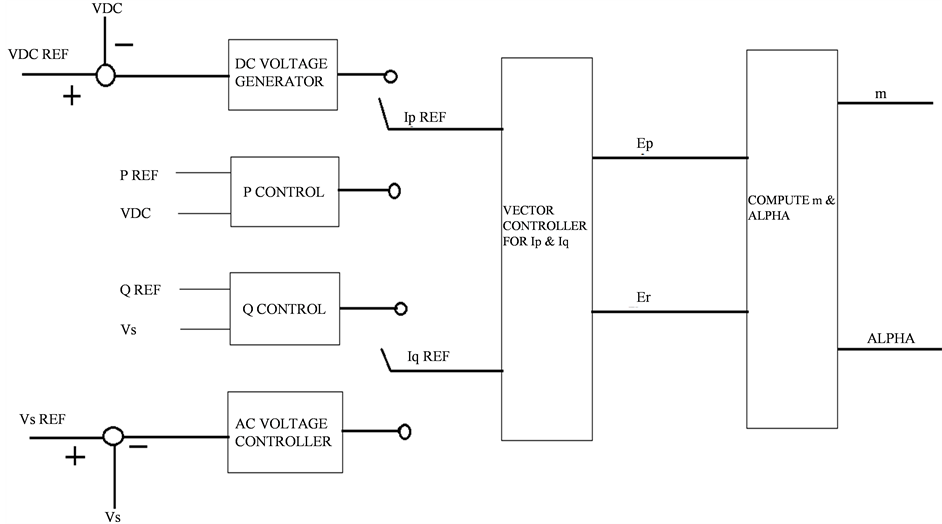
Figure 3. Block diagram of control scheme.
3.3. Artificial Neural Network
Artificial Neural Networks are networks of neurons arranged in layers. A minimum of three layers are required in the making of the back propagation feed forward ANN. The number neurons in the input layer and that in the output layer are determined by the number of elements in the input and output vectors of the system under consideration. In the making of a control system to mimic an ANFIS after the ANFIS has been developed in MATLAB/SIMULINK we have the error and the error rate inputs to the ANN. The first ANN unit considering the error and error inputs gives out the modulation index and the second ANN gives the Theta.
Thus we get the MI and the Theta from two ANN units. A general structure of the control scheme is as depicted in Figure 2.
4. Experimental Verification
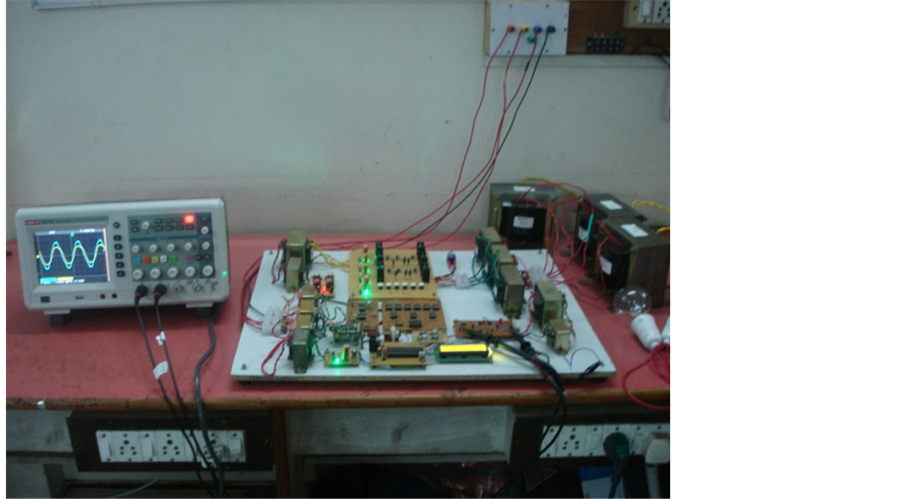
The real time implementation of the proposed system and its validation was carried out using a scaled down model. A solar panel with 80 W rating was used for the purpose. The output of the panel which is of around 17 V at maximum power output was first boosted to the required 400 V level using a boost DC to DC converter. The output of the boost converter was then applied to the three phase bridge inverter unit. The voltage source inverter was then connected to the three phase AC mains through the LCL filter unit.
The voltage and current measurements were carried out using potential and current transformers and after fed to the ARM 7 processor. The related control activities were carried out inside the ARM processor and the decisions were made using the built in ANN unit. This trained ANN unit is the coded version of the one we have developed in the MATLAB/SIMULINK environment. The modulation index and the phase angle were the two outputs of the ANN and using these two quantities the PWM was carried out. The PWM signals were then coupled to the MOSFETS used in the VSI (Figure 4(a)) using opto-couplers.
The Power injection into the grid had to be done based on the availability of the power source at the solar panel and at same time the load, in this case the grid, also exhibits changes in its impedance. The variations in solar insolation and the associated solar power generation and the variations in the grid impedance were the two challenges. The selection of the optimal MI and Theta to be used in the generation of the reference signal for the three phase VSI is the essence of this research. And this has been carried out using the ANN that got trained using the training data obtained after the ANFIS unit.
 (a)
(a) (b)
(b)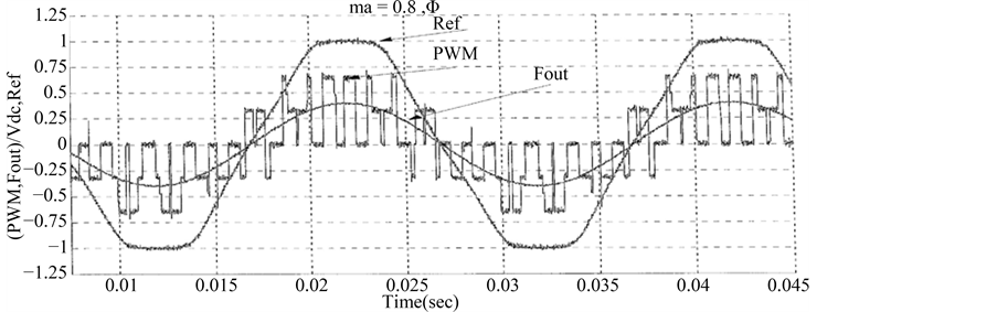 (c)
(c)
Figure 4. (a) Experimental setup; (b) ARM processor; (c) Reference signal, inverter output (PWM) and filter output (Fout).
Implementation of a trained unit in the ARM processor (Figure 4(b)) can be done by appropriately writing a function to represent the sigmoidal function of the neurons and then the synaptic weights in the form of multipliers.
Frequent changes in the power output of the solar power unit or the changes in the grid impedances cause disturbances to the power transaction as well as the power quality.
However when it can be observed from the waveforms and the THD of the terminal voltage after the filter at the grid terminals that the voltage waveforms are of better quality with the THD within the limit of 5%.
As mentioned earlier, Real Time Operating System based micro controller that can undertake multiple tasks is employed in this attempt. The three tasks to be carried out independently are
1. To monitor the output voltage continuously.
2. To send the switching pulses with appropriate theta for the DC-DC boost converter.
3. To send the switching pulses with appropriate MI for the VSI.
Each of the developed ICBT inverters was tested by driving the input from a DC power source and supplying a star-connected resistive load on the AC side. The reference signal, the PWM waveform generated of the phase to load neutral and the filter output are shown on Figure 4(c) for Modulation Index versus phase angle. It is clear that the magnitude of the reference signal has no effect on the inverter output. The output voltage magnitude is greatly affected by the modulation index. Also, the phase shift does not affect the magnitude of the inverter output voltage.
5. Results and Discussions
The Injection of power from the VSI onto the grid has been carried out using the ANFIS based controller. The power transactions, the FFT of the terminal voltages and the injected current are compared in this chapter. In this part output voltage and current waveforms of inverter have been shown. For nonlinear load a full wave rectifier with capacitive filter of 30 μF and a resistance of 50 Ω have been used. All the results were performed in isolated mode. Then THD of output voltage was calculated by FFT analysis and the obtained results are compared.
5.1. Fuzzy Logic Control
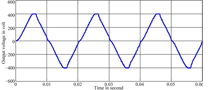
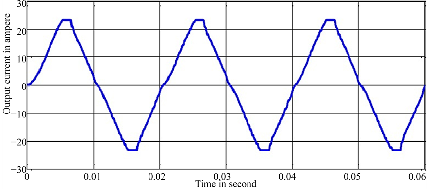
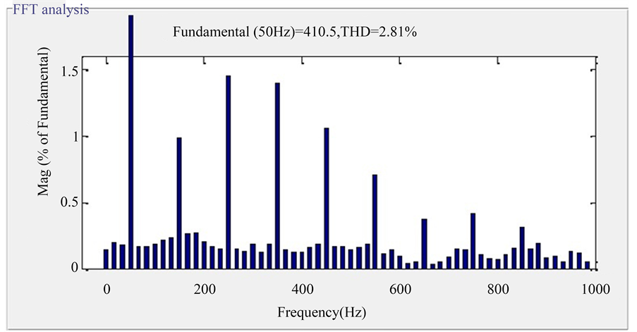
Here for linear load a resistance of 17.16 ohm is connected across inverter output. As the input dc supply is of 400 volt, an AC voltage of peak value 400 volt is obtained across output. The corresponding load limit is 23.31 ampere is opted as load current. Though output waveforms are approaching sinusoidal, yet output voltage contains some higher order harmonics. Corresponding harmonic spectrum of output voltage is shown in Figure 5(c) and it found that the THD of Vo is 2.81%.
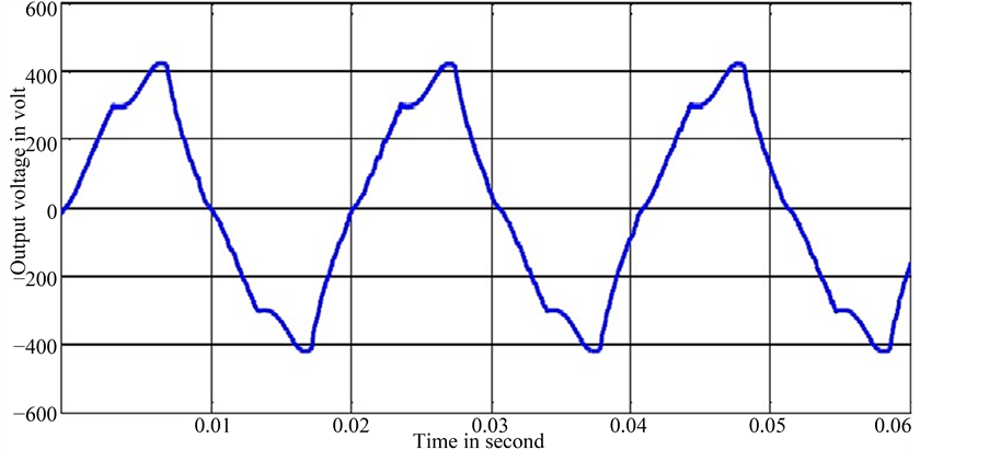
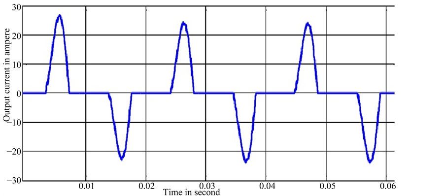
For a non-linear load a rectifier load is considered. As the rectifier uses switching devices, hence generates harmonics and then injects to source. Hence output voltage as well as output current is containing harmonics. As a result they are not sinusoidal which is expected to be so. When output voltage was analyzed through FFT the THD was found to be 15.08% given in Figure 5(f).
5.2. With ANFIS Controller
As ANFIS controller is based on principle ANN, it output performs the PI controller. In Figure 5(g) & Figure 5(h) output voltage and current are nearly sinusoidal. Its FFT analysis gives the THD of 0.69% given in Figure 5(i).
When this controller along with ANFIS is implemented in case of nonlinear load it shows better performance than Fuzzy Logic Controller. FFT analysis of output voltage gives THD of 4.53% given in Figure 5(l). From Table 1 shows ANFIS controller gives less %THD.
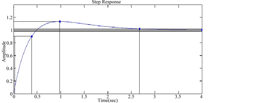
Based on the deduced transfer functions the step responses of the voltage and current controller of the three phase grid connected inverter are plotted in the MATLAB/Simulink environment.
In the Figure 6(a) step response of the dc-link voltage controller is shown. As the dc-link voltage controller is a slower one its rise time is set at 0.059 second. Its settling time is 2.675 second and having a peak overshoot of 13.3%.
In Figure 6(b) step response of the current compensator is shown. As the current controller is the faster one
 (a)
(a)
 (b)
(b)
 (c)
(c)
 (d)
(d)
 (e)
(e)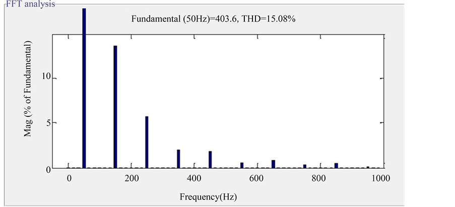 (f)
(f)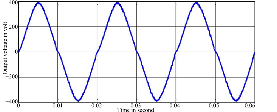 (g)
(g)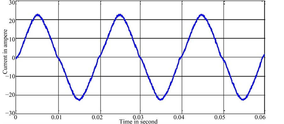 (h)
(h)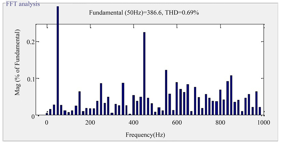 (i)
(i)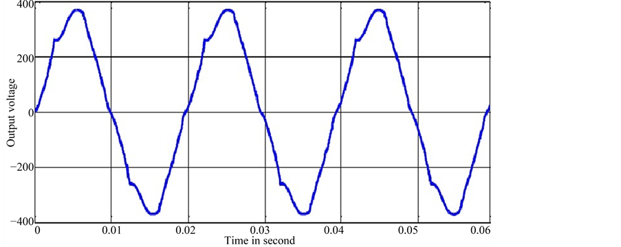 (j)
(j)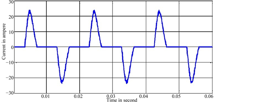 (k)
(k)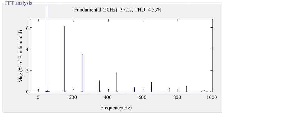 (l)
(l)
Figure 5. (a) Output voltage wave form of inverter (Linear Load); (b) Output current wave form of inverter (Linear Load); (c) THD of output voltage (Linear Load); (d) Output voltage wave form of inverter (Non-Linear Load); (e) Output current wave form of inverter (Non-Linear Load); (f) THD of output voltage (Non-Linear Load); (g) Output voltage wave form of inverter (Linear Load); (h) Output current wave form of inverter (Linear Load); (i) THD of output voltage (Linear Load); (j) Output voltage wave form of inverter (Non-Linear Load); (k) Output current wave form of inverter (Non-Linear Load); (l) THD of output voltage (Non-Linear Load).

Table 1. Comparison of %THD.
 (a)
(a)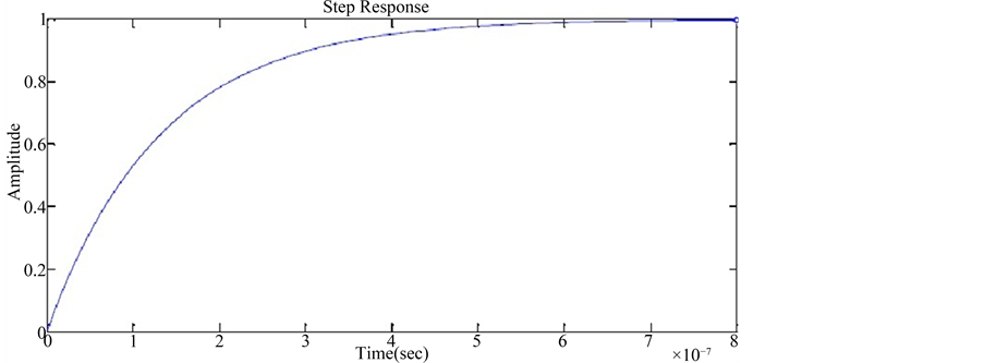 (b)
(b)
Figure 6. (a) Step response of voltage controller; (b) Step response of current controller.
it’s rise time is set to lesser than that of outer dc-link voltage controller. A control strategy is based on the goal of minimizing absolute error between the desired and the actual d-axis and q-axis currents through an adaptive tuning process. It is crucial to identify that fast current loop controller is necessary to assure highest power quality.
6. Conclusion
An ANFIS based control scheme for the management of the VSI connected to the grid was studied in detail. The results of the previous control schemes like H∞ controller, PI controller and fuzzy logic controllers were compared against the ANFIS model. The ANFIS model and its implementation through a trained ANN implemented in the ARM processor proved to be a better choice in this application. A control strategy was developed based on the model and its step responses were plotted. From the obtained results it is concluded that ANFIS controller gives less THD% in output voltage in case of both linear and non-linear load as compared to H∞ controller, PI controller and fuzzy logic controllers.
Cite this paper
D. Thalapathi Udhayakumar,P. S. Manoharan, (2016) Design and Implementation of ANFIS Controller Based Grid Connected Voltage Source Inverters in RTOS Environment. Circuits and Systems,07,2452-2466. doi: 10.4236/cs.2016.79212
References
- 1. Chen, C.L., Lai, J.S., Wang, Y.B., Park, S.Y. and Miwa, H. (2008) Design and Control for LCL-Based Inverters with Both Grid-Tie and Standalone Parallel Operations. IEEE Industry Applications Society Annual Meeting, Edmonton, 5-9 October 2008, 1-7.
http://dx.doi.org/10.1109/08ias.2008.326 - 2. Shen, G., Xu, D., Cao, L. and Zhu, X. (2008) An Improved Control Strategy for Grid-Connected Voltage Source Inverters with an LCL Filter. IEEE Transactions on Power Electronics, 23, 1899-1906.
- 3. Liserre, M., Teodorescu, R. and Blaabjerg, F. (2006) Stability of Photovoltaic and Wind Turbine Grid-Connected Inverters for a Large Set of Grid Impedance Values. IEEE Transactions on Power Electronics, 21, 263-272.
- 4. Li, Y., Vilathgamuwa, D.M. and Loh, P.C. (2004) Design, Analysis, and Real-Time Testing of a Controller for Multibus Microgrid System. IEEE Transactions on Power Electronics, 19, 1195-1204.
- 5. Yang, S., Ding, X., Liu, J. and Qian, Z. (2007) Analysis and Design of a Cost-Effective Voltage Feedback Control Strategy for EPS Inverters. IEEE Power Electronics Specialists Conference, Orlando, 17-21 June 2007, 477-482.
http://dx.doi.org/10.1109/pesc.2007.4342034 - 6. Asiminoaei, L., Teodorescu, R., Blaabjerg, F. and Borup, U. (2004) A New Method of On-Line Grid Impedance Estimation for PV Inverter. 19th Annual IEEE Applied Power Electronics Conference and Exposition, 3, 1527-1533.
http://dx.doi.org/10.1109/apec.2004.1296067 - 7. Willmann, G., Coutinho, D.F., Pereira, L.F.A. and Libano, F.B. (2007) Multiple-Loop H-Infinity Control Design for Uninterruptible Power Supplies. IEEE Transactions on Industrial Electronics, 54, 1591-1602.
- 8. Lee, T.S., Chiang, S.J. and Chang, J.M. (2001) H∞ Loop-Shaping Controller Designs for the Single-Phase UPS Inverters. IEEE Transactions on Power Electronics, 16, 473-481.
- 9. Li, Y.W., Vilathgamuwa, D.M. and Loh, P.C. (2007) Robust Control Scheme for a Microgrid with PFC Capacitor Connected. IEEE Transactions on Industry Applications, 43, 1172-1182.
- 10. Li, Y.W., Vilathgamuwa, D.M., Blaabjerg, F. and Loh, P.C. (2007) A Robust Control Scheme for Medium-Voltage- Level DVR Implementation. IEEE Transactions on Industrial Electronics, 54, 2249-2261.
- 11. Farrag, E.A.M. and Putrus, G.A. (2012) Design of an Adaptive Neurofuzzy Inference Control System for the Unified Power-Flow Controller. IEEE Transactions on Power Delivery, 27, 53-61.
http://dx.doi.org/10.1109/TPWRD.2011.2171061 - 12. Wang, L., Li, H.-W. and Wu, C.-T. (2013) Stability Analysis of an Integrated Offshore Wind and Seashore Wave Farm Fed to a Power Grid Using a Unified Power Flow Controller. IEEE Transactions on Power Systems, 28, 2211-2221.
http://dx.doi.org/10.1109/TPWRS.2013.2237928 - 13. Bloemink, J.M. and Green, T.C. (2013) Benefits of Distribution-Level Power Electronics for Supporting Distributed Generation Growth. IEEE Transactions on Power Delivery, 28, 911-919.
http://dx.doi.org/10.1109/TPWRD.2012.2232313 - 14. Golshannavaz, S., Aminifar, F. and Nazarpour, D. (2014) Application of UPFC to Enhancing Oscillatory Response of Series-Compensated Wind Farm Integrations. IEEE Transactions on Smart Grid, 5, 1961-1968.
http://dx.doi.org/10.1109/TSG.2014.2304071 - 15. Natália Santos, M.R., Fernando Silva, J. and Verveckken, J. (2014) Enhancing the Ride-Through Capability of DC- Link Voltage in NPC Multilevel Unified Power-Flow Controllers. IEEE Transactions on Power Delivery, 29, 1542- 1550.
http://dx.doi.org/10.1109/TPWRD.2014.2326774 - 16. Selvaperumal, S., Rajan, C.C.A. and Muralidharan, S. (2013) Stability and Performance Investigation of a Fuzzy- Controlled LCL Resonant Converter in an RTOS Environment. IEEE Transactions on Power Electronics, 28, 1817- 1832.
http://dx.doi.org/10.1109/TPEL.2012.2214236 - 17. Selvaperumal, S. and Rajan, C.C.A. (2012) Investigation of Closed-Loop Performance for an LCL Resonant Converter in a Real-Time Operating System Environment. IET Power Electronics, 5, 511-523.
http://dx.doi.org/10.1049/iet-pel.2011.0211 - 18. Pounraj, K., Rajasekaran, V. and Selvaperumal, S. (2013) Dynamic Performance Investigation of d-q Model with PID Controller-Based Unified Power-Flow Controller. IET Power Electronics, 6, 843-850.
http://dx.doi.org/10.1049/iet-pel.2012.0551 - 19. Selvaperumal, S. and Rajan, C.C.A. (2009) Micro-Controller Based LCC Resonant Converter Analysis, Design, and Simulation Results. International Journal of Computer and Electrical Engineering, 1, 323-327.
http://dx.doi.org/10.7763/IJCEE.2009.V1.51 - 20. Selvaperumal, S. and Rajan, C.C.A. (2009) Embedded Control of LCL Resonant Converter Analysis, Design, Simulation and Experimental Results. Engineering, 1, 1-54.
http://dx.doi.org/10.4236/eng.2009.11002 - 21. Park, S.Y., Chen, C.L., Sai, J.S. and Moon, S.R. (2008) Admittance Compensation in Current Loop Control for a Grid-Tie LCL Fuel Cell Inverter. IEEE Transactions on Power Electronics, 23, 1716-1723.
http://dx.doi.org/10.1109/TPEL.2008.924828 - 22. Abdel-Rahim, N. and Quaicoe, J.E. (1994) Modeling and Analysis of a Feedback Control Strategy for Three-Phase Voltage-Source Utility Interface Systems. Conference Record of the 1994 IEEE Industry Applications Society Annual Meeting, Denver, 2-6 October 1994, 895-902.
http://dx.doi.org/10.1109/IAS.1994.377524 - 23. Bierhoff, M.H. and Fuchs, F.W. (2009) Active Damping for Three-Phase PWM Rectifiers with High-Order Line-Side Filters. IEEE Transactions on Industrial Electronics, 56, 371-379.
http://dx.doi.org/10.1109/TIE.2008.2007950 - 24. Liserre, M., Blaabjerg, F. and Hansen, S. (2005) Design and Control of an LCL-Filter-Based Three-Phase Active Rectifier. IEEE Transactions on Industry Applications, 41, 1281-1291.
http://dx.doi.org/10.1109/TIA.2005.853373 - 25. Wang, F., Benhabib, M.C., Duarte, J.L. and Hendrix, M. (2009) Sequence-Decoupled Resonant Controller for Three- Phase Grid-Connected Inverters. Twenty-Fourth Annual IEEE Applied Power Electronics Conference and Exposition, 15-19 February 2009, 121-127.
http://dx.doi.org/10.1109/apec.2009.4802643 - 26. Castilla, M., Miret, J., Matas, J., Garcia de Vicuna, L. and Guerrero, J.M. (2009) Control Design Guidelines for Single- Phase Grid-Connected Photovoltaic Inverters with Damped Resonant Harmonic Compensators. IEEE Transactions on Industrial Electronics, 56, 4492-4501.
http://dx.doi.org/10.1109/TIE.2009.2017820 - 27. Zmood, D.N. and Holmes, D.G. (2003) Stationary Frame Current Regulation of PWM Inverters with Zero Steady-State Error. IEEE Transactions on Power Electronics, 18, 814-822.
http://dx.doi.org/10.1109/TPEL.2003.810852 - 28. Castilla, M., Miret, J., Matas, J., de Vicua, L.G. and Guerrero, J.M. (2008) Linear Current Control Scheme with Series Resonant Harmonic Compensator for Single-Phase Grid-Connected Photovoltaic Inverters. IEEE Transactions on Industrial Electronics, 55, 2724-2733.
http://dx.doi.org/10.1109/TIE.2008.920585 - 29. Twining, E. and Holmes, D.G. (2003) Grid Current Regulation of a Three-Phase Voltage Source Inverter with an LCL Input Filter. IEEE Transactions on Power Electronics, 18, 888-895.
http://dx.doi.org/10.1109/TPEL.2003.810838 - 30. Wang, Z.T. and Chang, L.C. (2008) A DC Voltage Monitoring and Control Method for Three-Phase Grid-Connected Wind Turbine Inverters. IEEE Transactions on Power Electronics, 23, 1118-1125.
http://dx.doi.org/10.1109/TPEL.2008.921174 - 31. Kazmierkowski, P.M. and Malesani, L. (1998) Current Control Techniques for Three-Phase Voltage-Source PWM Converters: A Survey. IEEE Transactions on Industrial Electronics, 45, 691-703.
http://dx.doi.org/10.1109/41.720325 - 32. Selvaraj, J. and Rahim, N.A. (2009) Multilevel Inverter for Grid-Connected PV System Employing Digital PI Controller. IEEE Transactions on Industrial Electronics, 56, 149-158.
http://dx.doi.org/10.1109/TIE.2008.928116 - 33. Carrasco, J.M., Franquelo, L.G., Bialasiewicz, J.T., Galván, E., Guisado, R.P., Prats, M.A. and Moreno-Alfonso, N. (2006) Power-Electronic Systems for the Grid Integration of Renewable Energy Sources: A Survey. IEEE Transactions on Industrial Electronics, 53, 1002-1016.
http://dx.doi.org/10.1109/TIE.2006.878356 - 34. Blaabjerg, F., Teodorescu, R., Liserre, M. and Timbus, A.V. (2006) Overview of Control and Grid Synchronization for Distributed Power Generation Systems. IEEE Transactions on Industrial Electronics, 53, 1398-1409.
http://dx.doi.org/10.1109/TIE.2006.881997