Circuits and Systems
Vol.07 No.06(2016), Article ID:66627,12 pages
10.4236/cs.2016.76082
An Innovative Design Approach to Control over Ad Hoc Networks
S. Subburam1, T. Senthilkumaran2, S. Revathi3, M. Mathivanan2
1Prince Shri Venkateshwara Padmavathy Engineering College, Chennai, India
2ACS College of Engineering, Bengaluru, India
3B. S Abdur Rahman University, Chennai, India

Copyright © 2016 by authors and Scientific Research Publishing Inc.
This work is licensed under the Creative Commons Attribution International License (CC BY).
http://creativecommons.org/licenses/by/4.0/


Received 30 March 2016; accepted 16 May 2016; published 20 May 2016
ABSTRACT
In Mobile ad hoc networks (MANETs), the mobile nodes are communicating trough wireless medium. The protocol designs of MANETs are based on a traditional approach which has been found ineffective to deal congestion related problems. Hence, it is affecting properties of physical layer, the network layer and transport layer. This paper proposes a novel design approach, deviating from the traditional network design, towards enhancing the cross-layer interaction among different layers, namely physical, MAC and network. The novel approach for congestion control is to solve congestion and mobility related problems with a cross layer interaction. The significance of CLCC is that it has used two mechanisms: (i) Dynamic Transmission Power Control algorithm that predicts a link breakage if it is likely to happen, (ii) Dynamic Congestion Estimation Technique, which analyzes traffic fluctuation and categorize congestion status perfectly. The proposed protocol reduces the route breakage and network congestion, hence reduces the control overhead and latency, and increases the packet delivery ratio. Through simulation, it is shown that the proposed protocol is simple, robust and effective.
Keywords:
Congestion, MAC, Link Breaks, Cross Layer

1. Introduction
A mobile ad hoc network works on the principle of one-hop neighbour node broadcasting, in which a transmission signal from the source node propagates to all neighbour nodes within its communication region [1] . Transmission power-related problems are common features affecting the functioning of mobile ad hoc networks. The inability to maintain a steady transmission power degrades the transmission range and signal strength, and hence the reliability of mobile ad hoc networks [2] [3] .
Transmission power related problems can affect all the layers of the stack, from physical to transport, and include: (i) long delay, (ii) packet losses and (iii) low throughput. Previously, the design of ad hoc network protocol has been largely based on the “layered approach”. In layered architecture, the designer or implementer of the protocol focuses on a particular layer, without being required to consider the parameters of the rest of the stack [4] - [6] . However, this has generally resulted in suboptimal performance of applications. To overcome this, the “cross-layer” approach has been found to address transmission power-related issues in mobile ad hoc networks. The cross-layer design deviates from the traditional network design approach in which each layer of the stack would be made to operate independently. A workgroup of the Internet Engineering Task Force [4] has been studying interlayer interactions and performance in mobile ad hoc networks. The interlayer interaction metrics and the benefits of information exchange among the lower layers, network layer and transport layer were also reported. At the transport layer, the node interference affects the level of transmission power and causes network congestion. In such networks, TCP-supported congestion control has been unreliable, the well known transport protocols, such as UDP, are unreliable, and since no mechanism of congestion detection has been provided [7] - [10] .
In this work, a new cross-layer optimization framework is proposed that gathers information about a node’s Receiving Signal Strength (RSS) by using hello packet. Using a dynamic transmission power control mechanism, every node computes minimum RSS, average RSS and maximum RSS. This information can help each node to know its neighbor’s positions and guide to dynamically manage its power levels. The Cross-Layer design approach for Congestion Control (CLCC) would help to find an effective route between the source and the destination. This cross-layer design approach was tested by simulation (NS2 simulator) and its performance over CAR and AODV are found to be better.
2. Cross-Layer Design Framework
The proposed cross-layer optimization framework allows modification of transmission power to be made at physical layer after knowing a node’s one-hop neighbor’s RSS information. The modified transmission power will help that node to dynamically vary its propagation range at the physical layer. This information is passed from the physical layer to the network layer so that it can take optimal decisions in routing protocols. A major advantage of this framework is that it allows access of information between physical layer and top layers (MAC and network layer). Figure 1 illustrates the cross-layer interaction between lower and higher layers.
2.1. Dynamic Transmission Power Control
Much of work on power management protocols for mobile ad hoc network is yet to reflect in literature. Without an effective transmission power control mechanism in place, packet transmissions can be affected by link instability, weak Receiving Signal Strength (RSS) and, network interference [10] . As noted above, the quality of RSS always depends on a broadcasting node’s transmission power. It is known that the broadcasting signal from one node travels omni-directionally to its one-hop neighbors. This research assumes that all nodes have the same
Figure 1. Cross-layer interactions between physical layer and network layer.
propagation range, which can be altered depending on the one-hop neighbors’ coverage. The node’s receiving signal strength has taken from MAC layer. This information helps to decide whether a current node is placed either in high or low signal strength area. After computing the RSS, the node broadcasts this information to its one-hop neighbours by hello packets (see Algorithm 1). These hello packers will also help to update all nodes’ RSS in the routing table. Then, each node computes the average RSS values of its neighbors and determines three communication regions (minimum range, average range and maximum range) [10] .
Equations (1) to (3) are used to find three threshold values (AMin_RSS―Average of Minimum RSS, AMax_RSS- Average of Maximum RSS, and A_RSS- Average RSS). Let n be the number of one-hop neighbors of node Xi and let RSSi represent the receiving signal strength of all neighbors of node Xi: Average RSS (A_RSS) of neighbors computed as follows.
 (1)
(1)
From these, two sets of nodes―Min_node (Minimum RSS neighbours which is less than A_RSS) and Max_node (Maximum RSS neighbours which is greater than A_RSS) and two averages, AMin_RSS and AMax_RSS, for both sets are computed as follows.
 (2)
(2)
 (3)
(3)
Using these values, AMin_RSS, AMax_RSS and A_RSS, every node then determines its communication region. The RSS values are always indirectly proportional to transmission distance (Weak RSS can cover maximum transmission distance). AMin_RSS covers the maximum communication region, while Amax_RSS covers the minimum communication region. Algorithm 1 describes the procedure for control of transmission power.
Algorithm 1: Algorithm for adjusting transmission power control
Begin
Node initiates Hello packet for gathering neighbors RSS value
Get number of neighbors and their RSS value
Receiving node checks its routing table neighbors RSS value
If value present
Update routing table
Else
Store as a new value
Calculate Average of RSS
If neighbors RSS value < Average RSS
Find Lower Average value say AMin_RSS
Else if neighbors RSS value > Average RSS
Find Upper Average value say AMax_RSS.
Segregate the regions of communication into three Transmission regions
Average of RSS region
Amax_RSS region
Amin_RSS region
End
Figure 2(a) shows the actual network without applying transmission power control algorithm. Figure 2(b) shows reduction of transmission range after applying adjusting transmission power control algorithm.


Figure 2. Modified networks (reducing transmission range).
Congestion in a network signifies that a node at any interval can become congested and starts to lose packets. Several metrics are available to monitor the congestion status at node level. For instance, it could be based on the average queue length and the percentage of packets discarded for lack of buffer space. Every node periodically checks the occupancy of its link layer queue using the dynamic congestion estimation technique so as to detect congestion well in advance. The Dynamic Congestion (DC) estimation technique is a queue management algorithm that makes use of a direct measurement of the congestion status.
Equations (4) to (8) are used to find three parameters, namely Minth, Maxth and wq to standardize its performance. Minth and Maxth are queue thresholds to present the current status of the queue, and wq is the queue weight parameter to compute the average queue size from the instantaneous queue length. The performance of DC depends on these thresholds. If the thresholds are small, then link utilization will be very low. If the thresholds are set too high, then congestion might occur even before the nodes are notified. To overcome this problem, we propose an effective threshold selection strategy.
 (4)
(4)
 (5)
(5)
Initially Maxth is set to twice the Minth, because the DC would function most effectively when Maxth- Minth is larger than the typical increase in the calculated average queue size in one round-trip time, and a useful rule is to set Maxth to at least twice of Minth [11] - [13] . For this reason, the Minimum threshold can be fixed as 40% total queue size. The weight parameter, wq, regulates network congestion and acts as a time constant of the low-pass filter. The average queue length is desired to track recurrent network congestion that happens over a long period and, at the same time, filter short time congestion.
This condition imposes a setback on the selection of wq. If wq is too small, the average queue length could not grasp the long-range congestion, which might result in ineffective congestion detection. If wq is too large, the average queue length follows the instantaneous queue length, which also degrades the performance of the congestion estimation technique. Therefore, the value of wq should be related to the flow of traffic in the queue [11] - [13] . The proposed DC algorithm would concentrate on assigning wq values dynamically according to the traffic flow. Equation (6) is used to set wq values dynamically. The wq ranges between 0 and 1 (0 < wq < 1) [11] - [13] . Equation (7) is used to calculate an average queue.
 (6)
(6)
where Inst_que means current queue size
The objective of average queue length is to incorporate all the traffic fluctuations, and it follows the long-term changes of Inst_que, reflecting persistent congestion in the networks. Equation (7) is used to find the average queue length [11] - [13] .
 (7)
(7)
 (8)
(8)
C is Constant value, if the average queue length is less than Minth, then the node is in zone I (safe zone). If the average queue length is greater than Minth and less than Maxth, then the node is likely to be in congestion and an alternative path discovery mechanism is initiated. Finally, if the average queue length is greater than Maxth, then the node’s congestion status becomes Zone-III (congested zone).
2.2. Primary Route Discovery
The main objective of routing protocols in ad hoc network is to find the shortest path between the source and the destination. Majorities of routing protocols are able to choose the shortest path but not a reliable path because, these routing protocols do not consider neighbor’s RSS value and neighbor’s congestion status. To overcome this limitation, as well as to reduce unnecessary RREQ packets and save network resources (link, buffer, battery), in this cross-layer optimization framework, every node applies a dynamic transmission power control mechanism and identifies three communication regions (minimum communication region, average communication region and maximum communication region). All nodes in the network update their transmission power based on an Amin_RSS value (maximum communication region). After adjusting transmission power, the protocol initiates CFS (Congestion Free Set) construction procedure. After construction of CFS, it initiates route discovery. In Cross-Layer Design Approach for Congestion Control (CLCC) route discovery, all nodes are not re-broad- casting; only selected nodes participate, reducing the flooding. For this, when a source node sends “unicast RREQ” packet to its next CFS node on the network, which is present its CFS neighbor’s table; CFS node shall decide whether or not to forward the RREQ packet.
When the CFS node receives this RREQ packet, it also checks its two-hop list. If the destination host is in its two-hop list, then the CFS node forwards the RREQ directly to the destination host. In case the destination host is not in its two-hop list, then it modifies the sequence number and hops count and forward this RREQ to the next CFS node to the network. The process is repeated until the destination host is found. Finally, the source finds a non-congested path to the destination. The destination responds to the first received RREQ and sends back an RREP packet. The RREP will travel back in the same path and add a new entry in its routing table. This path now becomes the primary route between the source and the destination. After a successful route discovery, the data packet is transmitted to the destination. Figure 4 illustrates the route discovery process. Figure 3 shows the route discovery after CFS selection, the first mobile host S checks its two-hop list to see whether it included the destination host D. If destination host D is not in this list, the sources host S forwards the RREQ packet to the next CFS node 3. Then, node 3 would check the two-hop list. If the destination is not inside it, the CFS node 3 forwards the RREQ to the next CFS node 6. The CFS host 6 would check the two-hop list. If the destination is
Figure 3. Route discovery process by using CFS node.
not inside it, the CFS node 6 forwards RREQ to the next CFS node 9. Finally node 9 finds that the destination node D is in the two-hop list, and so it forwards this packet through the CFS node 10 to the destination node D. The destination node D receives the RREQ packet and then returns it to the source. The RREP follows the reverse path of the RREQ to the source host. A route S ® 3 ® 6 ® 9 ® 10 ® D is found from source S to destination D.
2.3. Reliable Route Rediscovery
The primary path of a CFS node checks signal strength by using dynamic transmission power control algorithm. When a node’s signal strength is less than or equal to Amax_RSS (node is approaching), node’s signal strength is greater than Amax_RSS and less than or equal to A_RSS (node may be moving away or approaching), and node’s signal strength is greater than or equal to Amin_RSS(node is moving away). Every mobile node exchanges its RSS value by using a hello packet to its one-hop neighbors on the network. After receiving the hello packet from a neighboring CFS node, the predecessor CFS node will identify a new CFS node from its neighbor list, and then construct a new CFS from the current node to the destination and exchange it with its neighbors. When the CFS node receives a new CFS, it first compares the (Src, Dst) pair information in its routing table. If the entries do not match, it adds the new entry (CFS) in its routing table; otherwise, it updates itself in its routing table. Finally, the predecessor CFS node calls for a route discovery process to find a new route to the destination.
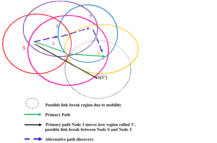
The alternative path finding algorithm does not incur any significant overhead, because for every CFS, only one extra broadcast message is necessary to inform one of the neighboring nodes to update its routing table, and also the alternative path discovery process incurs no extra cost. Figure 4, node 3 moves from a primary path to a new position, say 3’. By exchanging hello packet between node S and node 3, The signal strength of node 3 would be low due to mobility, which is now equal to Amin_RSS of node S. node S predicts link breakage between itself and node 3, it attempts to identify another CFS node in a maximum communication region and reestablish a route. Now node S establishes a new route by using intermediate nodes 2 and 5. Therefore, the new primary route is S → 2 → 5 → 6 → 9 → 10 → D.
Figure 4. Route rediscovery.
Algorithm 2: Reliable Route Rediscovery
Begin
Primary path node calculates RSS value using Dynamic transmission power control mechanism
if (current RSS value == predecessor node A_min RSS)
/* chance of Link break*/
Predecessor node initiates route discovery
If (alternative route found)
Packet transmission through alternative route
Else
Continue with existing path until route break.
End
3. Performance with Mobility of the Nodes.
The effect of node speed on the performance is also studied. Accordingly, the speed of the node are varied between 10 m/s and 35 m/s with a data flow pairs of 25, packet rate of 8/s, size of the network 100 nodes and high mobility. The results are collected as average values over 125 runs of simulation setting. They are compared with widely referred protocol CAR [14] .
3.1. End to End Delay
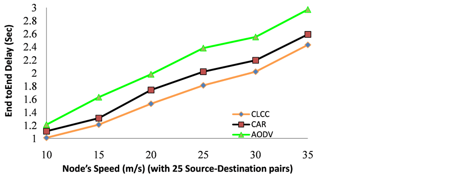
Figure 5 shows a comparison of end to end delay among three protocols CLCC, CAR and AODV. When a node’s mobility is low (10 m/s), the delay incurred by three protocols increase but not with large variation among the three. When the speed of a node is increased from 15 to 35 m/s, link breakage occurs frequently. In CAR, no special mechanism is present to predict link breakage, as a result, the CAR does route re-establishment mechanism after receiving a link break message. In AODV, after receiving a link break message, the source node would initiate a route request process to destination node, causing additional delay. However, in the proposed model (CLCC), a dynamic power control algorithm would predict if link breakage is likely to happen.
In this event, the algorithm will rediscover a new route and reestablish a route locally. Therefore, When CLCC is compared to CAR and AODV at node speed between 15 and 30 m/s; the delay is less and better performance around 8.29% over CAR and 22% over AODV. When the speed of node is high (35 m/s), the nodes are moving continuously in the network with frequent link breaks. In this situation, CLCC’s delay is less and the difference is around 5.81% only, compared CAR and less by 18.1% over AODV.
3.2. Packet Delivery Ratio
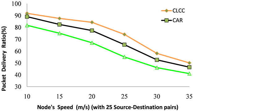
From Figure 6, it is seen that the packet delivery ratios among three protocols are almost similar at normal node speed (10 m/s). When node speed increases from 15 to 35 m/s, there is a decrease in delivery ratio for three pro-
Figure 5. End to end delay vs. node speed.
Figure 6. Packet delivery ratio vs. node speed.
tocols. This is because of frequent link breaks and data packet losses, requiring to construct a fresh route between the source and the destination. This new route discovery process is costlier because numerous RREQ packets need to be generated and transmitted, leading to network congestion. This retransmission of RREQ packets will consume more network resources and pull down the network performance. CLCC is able to deliver more data packets than AODV because it uses three transmission regions (minimum, average, maximum) based on receiver node’s receiving signal strength, and that a source node can chose a maximum transmission region node( Minimum RSS value) for broadcasting.
As a result, it is to lose only fewer data packets as compared with CAR and AODV. At node speed between 15 m/s and 30 m/s, the packet delivery ratio of CLCC is higher by around 8% than CAR and 20% than AODV. When the speed of node is very high (30 to 35 m/s), the delivery ratio decreases for both protocols CAR and AODV, but CLCC performs better than CAR by 8% and better than AODV by 19.7% with the possibility of more modification of the route. Similarly additional control packets required to reconstruct the route on link failure, or to reestablish a new route on link failure, or to reestablish a new route sensing the congestion due to node mobility is analyzed and is given in Figure 6.
3.3. Routing Overhead
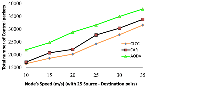
With regard to routing overhead as seen from Figure 7, when the speed of the node is normal (10 m/s), CLCC performs slightly better than CAR and AODV. This is because at 10 m/s the possibility of link break is low and the new route discovery is minimized. When nodes move faster in a network (15 to 35 m/s), frequent link breaks can happen. The AODV then initiates a new route request process by using RREQ packets. More number of RREQ packets being broadcasted leads to routing overhead in a network and degrades network performance. Our proposed algorithm (CLCC) has a dynamic power control mechanism that helps all nodes to predict link breaks well in advance. This information will support nodes to make early decisions to resolve link breaks locally.
The advantage of this mechanism to adjust their transmission power based on node’s receiving signal strength, helps to segregate nodes as weak link nodes and strong link nodes. The RREQ packets are forwarded only from strong link nodes. Therefore, the routing overhead decreases, compared to AODV. When the speed of node is 15 to 30(m/sec), the CLCC consumes around 10% less control packets than CAR and around 23.74% less control packets than AODV. When the speed of node is very high (30 to 35 m/s), CLCC performs better and requires 6.6% less control packets than CAR and 16.6% less control packets than AODV. This is because, the CLCC can anticipate link break by using dynamic power control mechanism and find an alternative path locally. But, the CAR and AODV can react only after link break happens and tries to establish a new route to the destination by broadcasting a route request. Therefore, CLCC consumes less control packets than CAR and AODV.
4. Effect of Network Size
The effect of network-size on the performance is also studied. Accordingly, the sizes of the networks are varied
Figure 7. Routing overhead vs. node speed.
between 125 nodes and 250 nodes with data flows in up to 25% of network size, Terrain Size 1400X1400, packet rate of 8/s, maximum speed 20 m/s and high mobility. The results are collected as average values over 125 runs of simulation setting.
4.1. Packet Delivery Ratio
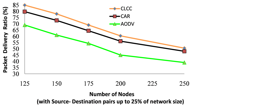
Figure 8 illustrates the effect of packet delivery ratio with varying node densities. As the node density increases the packet delivery ratio of AODV decreases more quickly, where as the delivery ratio of CLCC is maintained considerably better in the performance. As seen in Figure 8, the packet delivery ratio of CLCC is nearly the same as that of CAR but much better than AODV, in the case of lower node density (number of nodes =125). When the node density increases, the RREQ broadcast packets, as a result of link break also increases; this adds more packets to the queue of each node and increases the average waiting time of packets in each node. In addition, higher density seems to have negative effect to data delivery rate, which is true for AODV. However, for CLCC, the effect is around 6% decrease than CAR and around 18% decrease than AODV.
The reason for this that the CLCC executes a dynamic transmission control mechanism, which helps to forecast of link break and avoids packet drops particularly in higher network densities and the use of reduced number of control over head during path construction. As compared to AODV, node density has less impact on CLCC protocol, which is apparently a direct consequence of much fewer RREQ broadcasts. When the size of the network is increased from 150 to 200, the packet delivery ratio of CLCC is from 20% to 26% better compared to AODV and around 6% better compared to CAR. Moreover, when the size of the network is increased to 250 nodes, the CLCC shows a 23.5% performance improvement over AODV and 5.8% performance improvement over CAR.
4.2. Routing Overhead
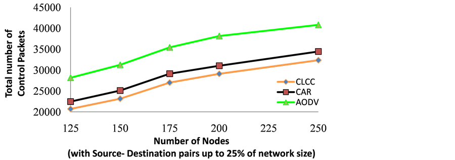
Figure 9 shows the routing overhead generated throughout the entire simulation with varying the number of nodes in the network. Most of routing packets generated are for the route discovery process. Route request messages are forwarded to the destination by broadcast in AODV, whereas in CLCC, only few nodes participated in the route discovery process by unicast; hence, not many route request packets are sent out. As a result, the overall saving in control overhead is better than AODV. Thus CLCC’s dynamic congestion estimation technique helps in reduction of congestion level caused by control packets and utilizes the bandwidth better.
When the size of the network is with 125 nodes, the routing overhead of CLCC is lesser than that of AODV and CAR. When the size of the network is increased from 150 to 175 nodes, it is clear from Figure 9 that the number of control messages used by AODV to discover and maintain the discovered path increases heavily with the increase of number of nodes in the network. This increased routing overhead leads to congestion in the network and hence the degradation in the routing performance. In contrast to AODV, the number of routing over-
Figure 8. Packet delivery ratio vs. node densities.
Figure 9. Routing overhead vs. node densities.
heads used by CLCC is very less. Compared to AODV, the routing overhead is lesser by 27% for CLCC than AODV and around 12% is lesser than CAR. This improvement is due to the dynamic transmission power control mechanism in CLCC that helps to alter a node’s transmission power according to its receiving signal strength, which in turn would help to reduce packet collision and unnecessary rebroadcasting of control packets and it could resolve congestion by using the CFS (congestion free set). With the size of the network is further increased to 200 nodes, the CLCC demonstrated only around 25.3% reductions in control packets than AODV and 10.4% reductions in control packets than CAR. This is because of the fact that, when more nodes are communicating it leads to collision. Moreover, when the size of the network is increased to 250 nodes, the CLCC shows 19.7% performance improvement over AODV and 10.1% performance improvement over CAR.
4.3. End to End Delay
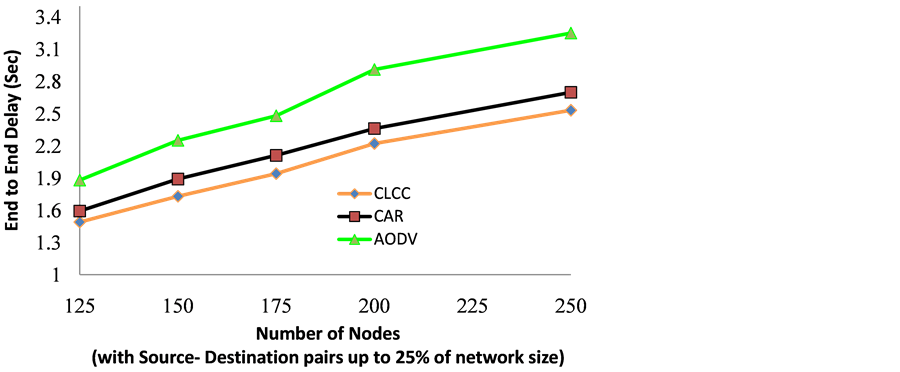
Figure 10 compares the end to end delay among three protocols CLCC, CAR and AODV. In general, delay of any scheme increases as network size increases whereas in CLCC, the end to end delays are comparatively lesser to that of CAR and AODV. When the size of the network is 125 nodes, the delay variation among CLCC, CAR and AODV are minimum. When the size of the network grows from 150 to 200 nodes, AODV and CAR initiate a new path discovery from the source end only after the link failure is detected; where as in the proposed protocol uses a dynamic power control mechanism to detect probable link breaks and an early action is taken on fixing up the problem locally. Due to this, the delay in CLCC is less by 10% than that of CAR and around 22.6% lesser than AODV. Moreover, when the network size is increased to 250 nodes, the CLCC demonstrated a re- duction performance, but only around 7.63% compared to CAR and around 23% is less than AODV, because of
Figure 10. End to end delay vs. node densities.
collisions. As it is seen from Figure 10, the difference in delay is almost maintained with increase in node density.
5. Conclusion
Link breakage can cause serious impairment in network performance, because the cost of new route finding is very high. In traditional route finding methods, the source node (or intermediate node) floods the entire network with RREQ packets to obtain the new route to destination. Whereas, in the proposed model (CLCC), a dynamic transmission power control algorithm predicts a link breakage and discovers a new route to be updated in the routing table. Firstly, each node gathers its neighbors’ Receiving Signal Strength (RSS) and constructs three transmission ranges, namely maximum, average, and minimum. Secondly, each node alters its transmission power based on maximum transmission range. Since the path finding process is based on neighbor’s RSS value and transmission range, the approach will find path before it fails, avoiding the source to reestablish a new path all over again. It has been verified by simulation that the performance of CLCC is appreciably better than that of CAR and AODV in terms of end to end delay, packet delivery ratio and routing overhead.
Cite this paper
S. Subburam,T. Senthilkumaran,S. Revathi,M. Mathivanan, (2016) An Innovative Design Approach to Control over Ad Hoc Networks. Circuits and Systems,07,971-982. doi: 10.4236/cs.2016.76082
References
- 1. Park, S. and Yoo, S.-M. (2013) An Efficient Reliable One-Hop Broadcast in Mobile Ad Hoc Networks. Ad Hoc Networks, 11, 19-28.
http://dx.doi.org/10.1016/j.adhoc.2012.03.021 - 2. Goldsmith, J. and Wicker, S.B. (2002) Design Challenges for Energy Constrained Ad-Hoc Wireless Networks. IEEE Wireless Communication, 9, 8-27.
http://dx.doi.org/10.1109/MWC.2002.1028874 - 3. Kawadia, V. and Kumar, P.R. (2005) Principles and Protocols for Power Control in Wireless Ad-Hoc Networks. IEEE Journal on Selected Areas in Communication, Part I, 23, 78-88.
http://dx.doi.org/10.1109/jsac.2004.837354 - 4. (2001) The National Science Foundation and Office of Naval Research Jointly Held a Workshop on Cross-Layer Design in Adaptive Ad Hoc Networks.
- 5. Srivastava, V. and Motani, M. (2005) Cross Layer Design: A Survey and the Road ahead. IEEE Communication Magazine, 43, 112-119.
http://dx.doi.org/10.1109/MCOM.2005.1561928 - 6. Foukalas, F., Gazis, V. and Alonistioti, N. (2008) Cross-Layer Design Proposals for Wireless Mobile Networks: A Survey and Taxonomy”, University of Athens. IEEE Communications Surveys and Tutorials, 10, 70-84.
http://dx.doi.org/10.1109/COMST.2008.4483671 - 7. Lochert, C., Scheuermann, B. and Mauve, M. (2007) A Survey on Congestion Control for Mobile Ad-Hoc Networks. Wiley Wireless Communications and Mobile Computing, 7, 655-676.
http://dx.doi.org/10.1002/wcm.524 - 8. Senthilkumaran,T. and Sankaranarayanan, V. (2013) Dynamic Congestion Detection and Control Routing in Ad Hoc Networks. Journal of King Saud University-Computer and Information Sciences, 25, 165-175.
http://dx.doi.org/10.1016/j.jksuci.2012.05.004 - 9. Senthilkumaran,T. and Sankaranarayanan, V. (2011) Early Congestion Detection and Adaptive Routing in MANET. Egyptian Informatics Journal, 12, 65-175.
http://dx.doi.org/10.1016/j.eij.2011.09.001 - 10. Ahmed, A.S., Kumaran, T.S., Syed, S.S.A. and Subburam, S. (2015) Cross-Layer Design Approach for Power Control in Mobile Ad Hoc Networks. Egyptian Informatics Journal, 16, 1-7.
http://dx.doi.org/10.1016/j.eij.2014.11.001 - 11. Floyd, S. and Jacobson, V. (1993) Random Early Detection Gateways for Congestion Avoidance. IEEE/ACM Transaction on Networking, 1, 397-413.
http://dx.doi.org/10.1109/90.251892 - 12. Floyd, S. (2000) Recommendation on Using the “Gentle” Variant of RED.
- 13. Floyd, S., Gummadi, R. and Shenker, S. (2001) Adaptive RED: An Algorithm for Increasing the Robustness of RED’s Active Queue Management.
- 14. Tran, D.A. and Raghavendra, H. (2006) Congestion Adaptive Routing in Mobile Ad Hoc Networks. IEEE Transactions on Parallel and Distributed Systems, 17, 16-28.
http://dx.doi.org/10.1109/tpds.2006.151


