Paper Menu >>
Journal Menu >>
 Energy and Power Engineering, 2010, 2, 313-319 doi:10.4236/epe.2010.24044 Published Online November 2010 (http://www.SciRP.org/journal/epe) Copyright © 2010 SciRes. EPE Experimental Investigation of Boundary Layer Characteristics on Blade Surface under Different Inlet Flow Conditions Xiangfeng Bo, Bo Liu, Pengcheng Zhao, Zhiyuan Cao National Aerodynamics Lab. of Airfoil and Cascade, School of Engine and Energy, Northwestern Polytechnical University, Xi’an, China E-mail: bxfa209@mail.nwpu.edu.cn, liubo704@nwpu.edu.cn Received July 18, 2010; revised September 4, 2010; accepted October 24, 2010 Abstract In this paper, an experimental study is conducted on cascade boundary layer under different inlet conditions. New method is used to measure the total pressure in blade surface boundary layer directly using total pres- sure probe. Total pressure in both suction and pressure surfaces are acquired at different inlet conditions by changing incidence angle and inlet Mach number. In addition, a series of parameters related to boundary layer characteristics are calculated. The objective of the experiment is to investigate the influence of inlet flow conditions on them. The results indicate that influence of incidence angle is significant when other con- ditions are the same. Displacement thickness, momentum thickness as well as other parameters display some disciplines for variation. In contrast, inlet Mach number has only a small influence in that boundary layer becomes a litter thinner with increasing Mach number. Comparisons of experimental results with theoretical expectations demonstrate that the method in this experiment is effective and reliable. Keywords: Boundary Layer, Cascade, Inlet Flow Conditions, Total Pressure Probe 1. Introduction Modern developing trend for aero-engine is toward high performance, wide range of work, high efficiency and high thrust-to-weight ratio [1-3]. Compressor is a key component of aero-engine which holds a large share in size and weight. Therefore, improving the performance of fan and compressor plays a vital role [4]. End-wall boundary layer, blade surface boundary layer and their interaction lead to great flow loss. Inlet flow conditions have an important impact for boundary layer on its development, separation and transition [5-6]. Along history, wind tunnel experiment is always an im- portant method for research. In early times only inlet or outlet flow parameters are directly measured. This method does no help to understand the specific loss mechanism in cascade. With the variation of research emphasis, the whole flow conditions in cascade need to be investigated. Many scholars have already conducted such experiments and provided some valuable results [7-9]. In this paper, an experimental research on both suction and pressure surface boundary layer is conducted on high subsonic cascade wind tunnel. The impacts of different inlet flow conditions on boundary layer characteristics are discussed in-depth. Experimental investigation is conducted to get detailed information about the velocity, displacement thickness and momentum thickness of boundary layer. 2. Design of Experiment and Experimental Devices 2.1. Design of Experiment Total pressure in boundary layer on both suction and pressure surface is measured using total pressure probe. The cascade wind tunnel is composed of gas source, regulator section, convergence section, experimental section, end wall boundary layer suction devices and control system. The wind tunnel structure is showed in Figure 1. Parameters of the tested cascade are in Table 1. The total pressure probe can only measure one posi- 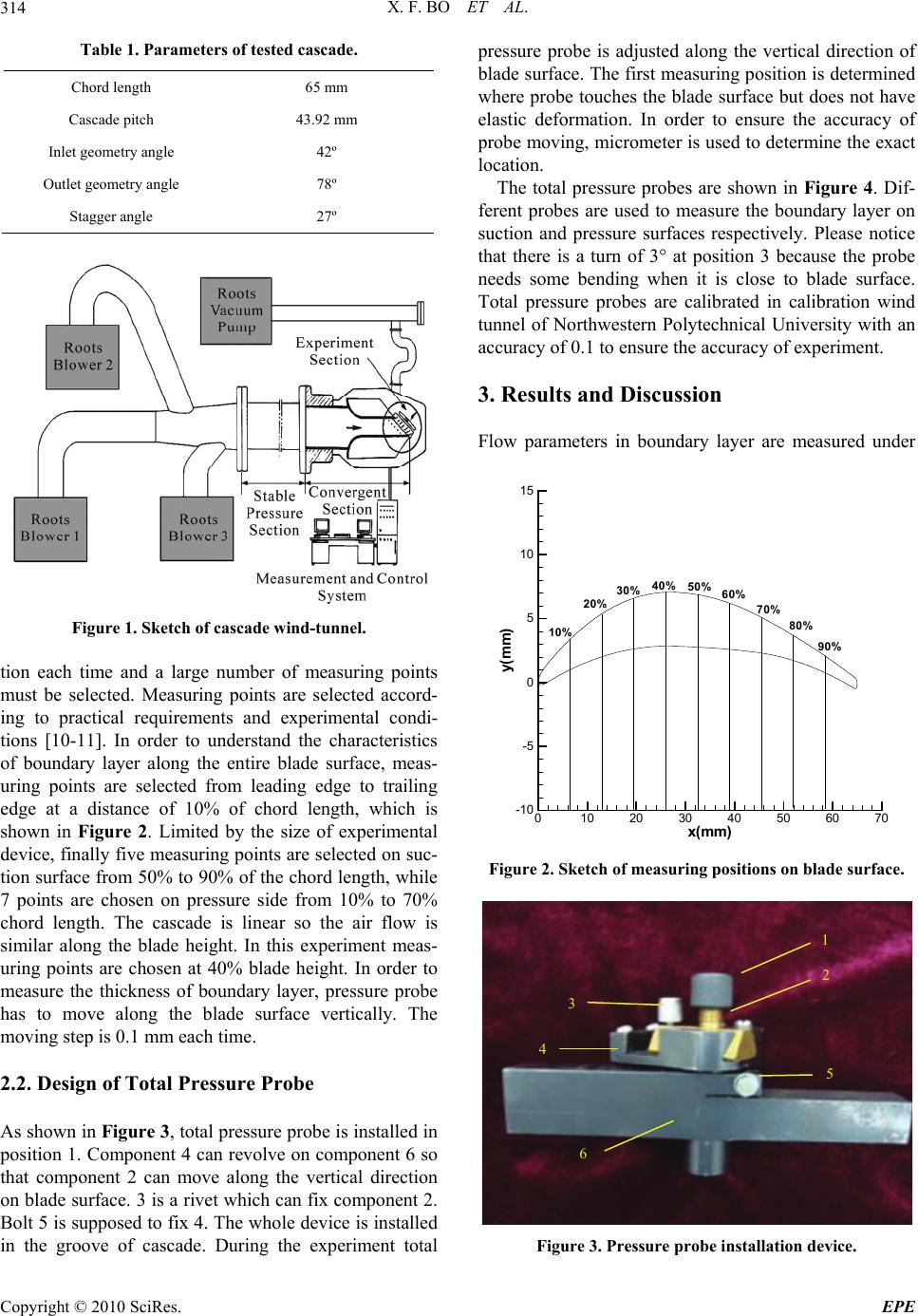 X. F. BO ET AL. Copyright © 2010 SciRes. EPE 314 Table 1. Parameters of tested cascade. Chord length 65 mm Cascade pitch 43.92 mm Inlet geometry angle 42º Outlet geometry angle 78º Stagger angle 27º Figure 1. Sketch of cascade wind-tunnel. tion each time and a large number of measuring points must be selected. Measuring points are selected accord- ing to practical requirements and experimental condi- tions [10-11]. In order to understand the characteristics of boundary layer along the entire blade surface, meas- uring points are selected from leading edge to trailing edge at a distance of 10% of chord length, which is shown in Figure 2. Limited by the size of experimental device, finally five measuring points are selected on suc- tion surface from 50% to 90% of the chord length, while 7 points are chosen on pressure side from 10% to 70% chord length. The cascade is linear so the air flow is similar along the blade height. In this experiment meas- uring points are chosen at 40% blade height. In order to measure the thickness of boundary layer, pressure probe has to move along the blade surface vertically. The moving step is 0.1 mm each time. 2.2. Design of Total Pressure Probe As shown in Figure 3, total pressure probe is installed in position 1. Component 4 can revolve on component 6 so that component 2 can move along the vertical direction on blade surface. 3 is a rivet which can fix component 2. Bolt 5 is supposed to fix 4. The whole device is installed in the groove of cascade. During the experiment total pressure probe is adjusted along the vertical direction of blade surface. The first measuring position is determined where probe touches the blade surface but does not have elastic deformation. In order to ensure the accuracy of probe moving, micrometer is used to determine the exact location. The total pressure probes are shown in Figure 4. Dif- ferent probes are used to measure the boundary layer on suction and pressure surfaces respectively. Please notice that there is a turn of 3° at position 3 because the probe needs some bending when it is close to blade surface. Total pressure probes are calibrated in calibration wind tunnel of Northwestern Polytechnical University with an accuracy of 0.1 to ensure the accuracy of experiment. 3. Results and Discussion Flow parameters in boundary layer are measured under x(mm) y(mm) 010 20 30 40 50 60 70 -10 -5 0 5 10 15 10% 20% 30% 40% 50% 60% 70% 90% 80% Figure 2. Sketch of measuring positions on blade surface. 1 2 3 4 5 6 Figure 3. Pressure probe installation device. 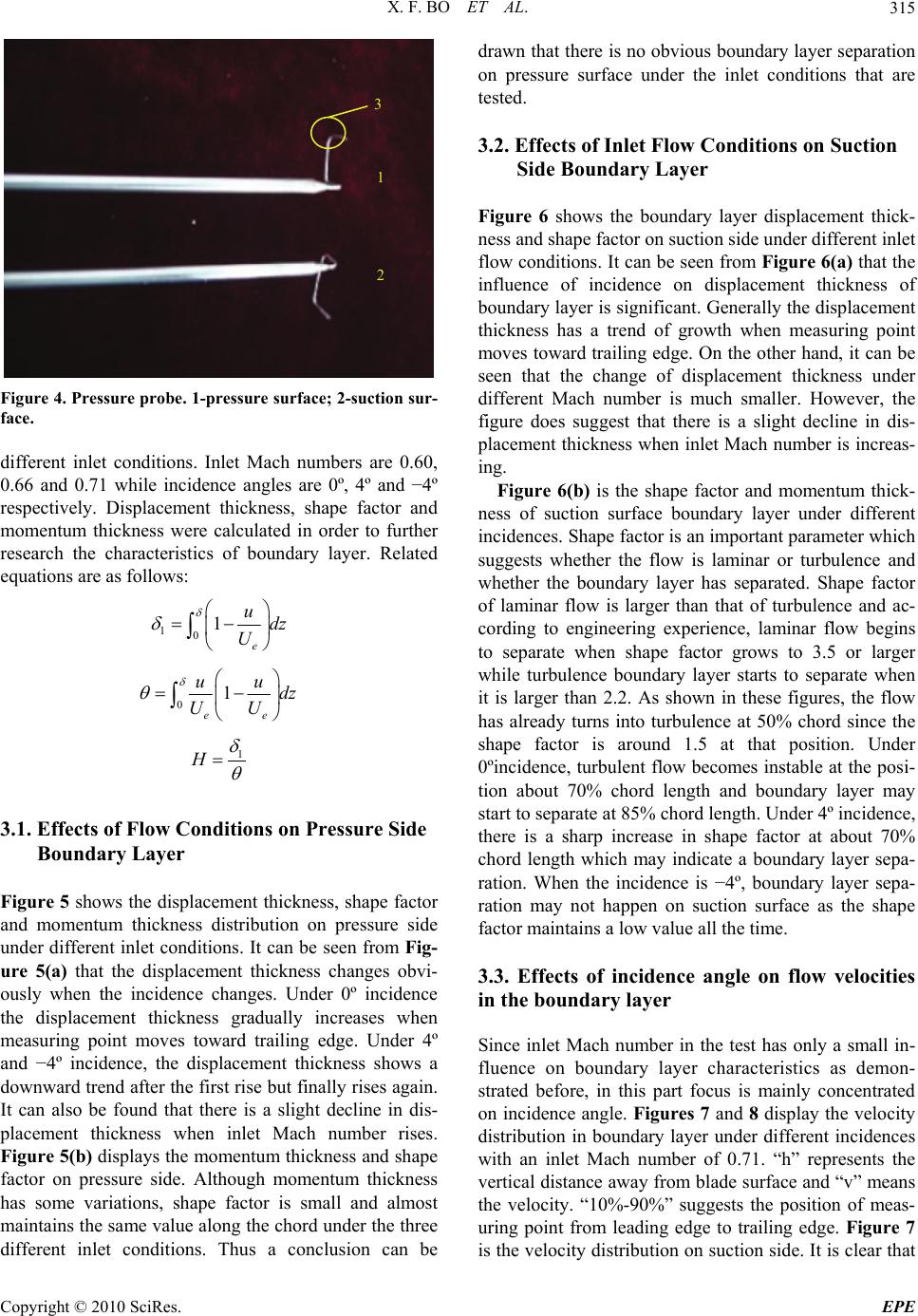 X. F. BO ET AL. Copyright © 2010 SciRes. EPE 315 1 2 3 Figure 4. Pressure probe. 1-pressure surface; 2-suction sur- face. different inlet conditions. Inlet Mach numbers are 0.60, 0.66 and 0.71 while incidence angles are 0º, 4º and −4º respectively. Displacement thickness, shape factor and momentum thickness were calculated in order to further research the characteristics of boundary layer. Related equations are as follows: 101 e udz U 01 ee uu dz UU 1 H 3.1. Effects of Flow Conditions on Pressure Side Boundary Layer Figure 5 shows the displacement thickness, shape factor and momentum thickness distribution on pressure side under different inlet conditions. It can be seen from Fig- ure 5(a) that the displacement thickness changes obvi- ously when the incidence changes. Under 0º incidence the displacement thickness gradually increases when measuring point moves toward trailing edge. Under 4º and −4º incidence, the displacement thickness shows a downward trend after the first rise but finally rises again. It can also be found that there is a slight decline in dis- placement thickness when inlet Mach number rises. Figure 5(b) displays the momentum thickness and shape factor on pressure side. Although momentum thickness has some variations, shape factor is small and almost maintains the same value along the chord under the three different inlet conditions. Thus a conclusion can be drawn that there is no obvious boundary layer separation on pressure surface under the inlet conditions that are tested. 3.2. Effects of Inlet Flow Conditions on Suction Side Boundary Layer Figure 6 shows the boundary layer displacement thick- ness and shape factor on suction side under different inlet flow conditions. It can be seen from Figure 6(a) that the influence of incidence on displacement thickness of boundary layer is significant. Generally the displacement thickness has a trend of growth when measuring point moves toward trailing edge. On the other hand, it can be seen that the change of displacement thickness under different Mach number is much smaller. However, the figure does suggest that there is a slight decline in dis- placement thickness when inlet Mach number is increas- ing. Figure 6(b) is the shape factor and momentum thick- ness of suction surface boundary layer under different incidences. Shape factor is an important parameter which suggests whether the flow is laminar or turbulence and whether the boundary layer has separated. Shape factor of laminar flow is larger than that of turbulence and ac- cording to engineering experience, laminar flow begins to separate when shape factor grows to 3.5 or larger while turbulence boundary layer starts to separate when it is larger than 2.2. As shown in these figures, the flow has already turns into turbulence at 50% chord since the shape factor is around 1.5 at that position. Under 0ºincidence, turbulent flow becomes instable at the posi- tion about 70% chord length and boundary layer may start to separate at 85% chord length. Under 4º incidence, there is a sharp increase in shape factor at about 70% chord length which may indicate a boundary layer sepa- ration. When the incidence is −4º, boundary layer sepa- ration may not happen on suction surface as the shape factor maintains a low value all the time. 3.3. Effects of incidence angle on flow velocities in the boundary layer Since inlet Mach number in the test has only a small in- fluence on boundary layer characteristics as demon- strated before, in this part focus is mainly concentrated on incidence angle. Figures 7 and 8 display the velocity distribution in boundary layer under different incidences with an inlet Mach number of 0.71. “h” represents the vertical distance away from blade surface and “v” means the velocity. “10%-90%” suggests the position of meas- uring point from leading edge to trailing edge. Figure 7 is the velocity distribution on suction side. It is clear that 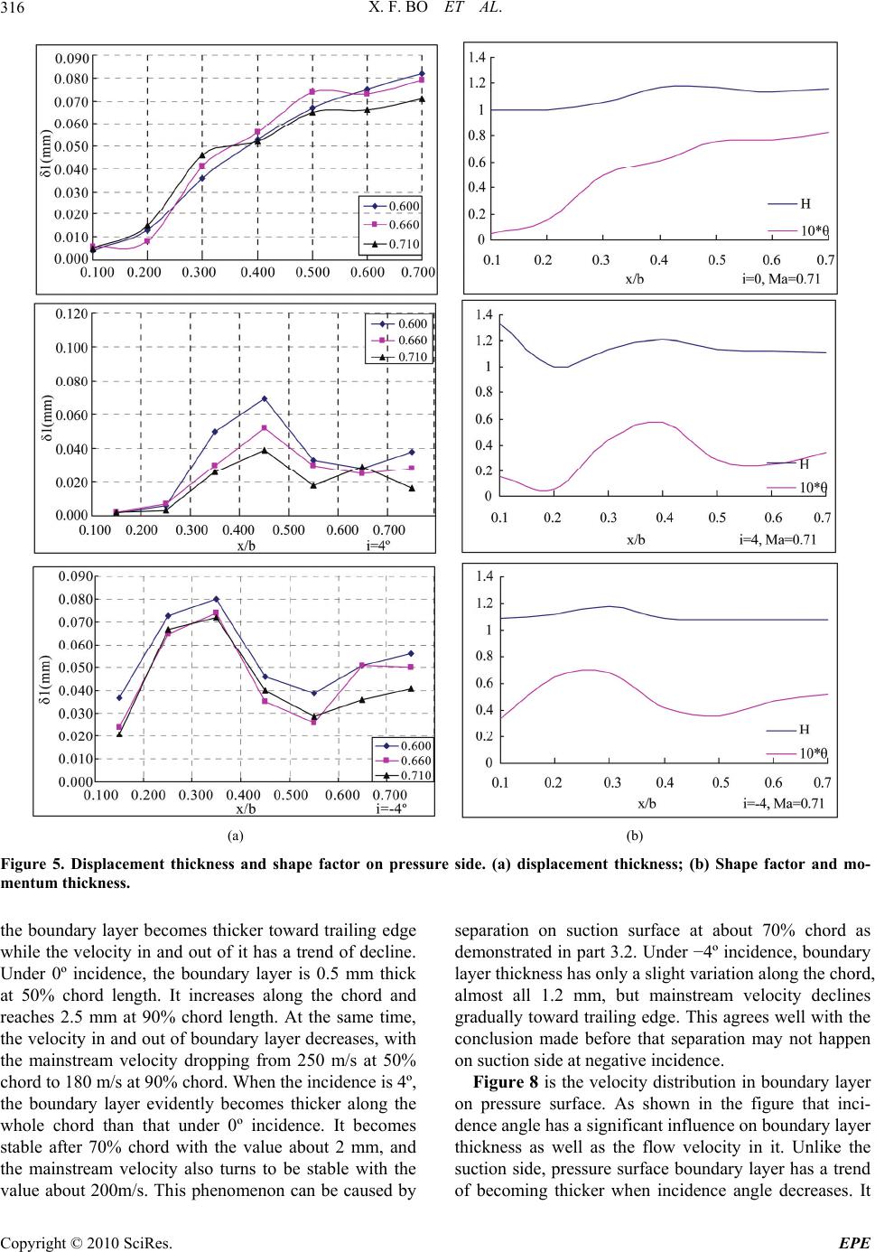 X. F. BO ET AL. Copyright © 2010 SciRes. EPE 316 (a) (b) Figure 5. Displacement thickness and shape factor on pressure side. (a) displacement thickness; (b) Shape factor and mo- mentum thickness. the boundary layer becomes thicker toward trailing edge while the velocity in and out of it has a trend of decline. Under 0º incidence, the boundary layer is 0.5 mm thick at 50% chord length. It increases along the chord and reaches 2.5 mm at 90% chord length. At the same time, the velocity in and out of boundary layer decreases, with the mainstream velocity dropping from 250 m/s at 50% chord to 180 m/s at 90% chord. When the incidence is 4º, the boundary layer evidently becomes thicker along the whole chord than that under 0º incidence. It becomes stable after 70% chord with the value about 2 mm, and the mainstream velocity also turns to be stable with the value about 200m/s. This phenomenon can be caused by separation on suction surface at about 70% chord as demonstrated in part 3.2. Under −4º incidence, boundary layer thickness has only a slight variation along the chord, almost all 1.2 mm, but mainstream velocity declines gradually toward trailing edge. This agrees well with the conclusion made before that separation may not happen on suction side at negative incidence. Figure 8 is the velocity distribution in boundary layer on pressure surface. As shown in the figure that inci- dence angle has a significant influence on boundary layer thickness as well as the flow velocity in it. Unlike the suction side, pressure surface boundary layer has a trend of becoming thicker when incidence angle decreases. It 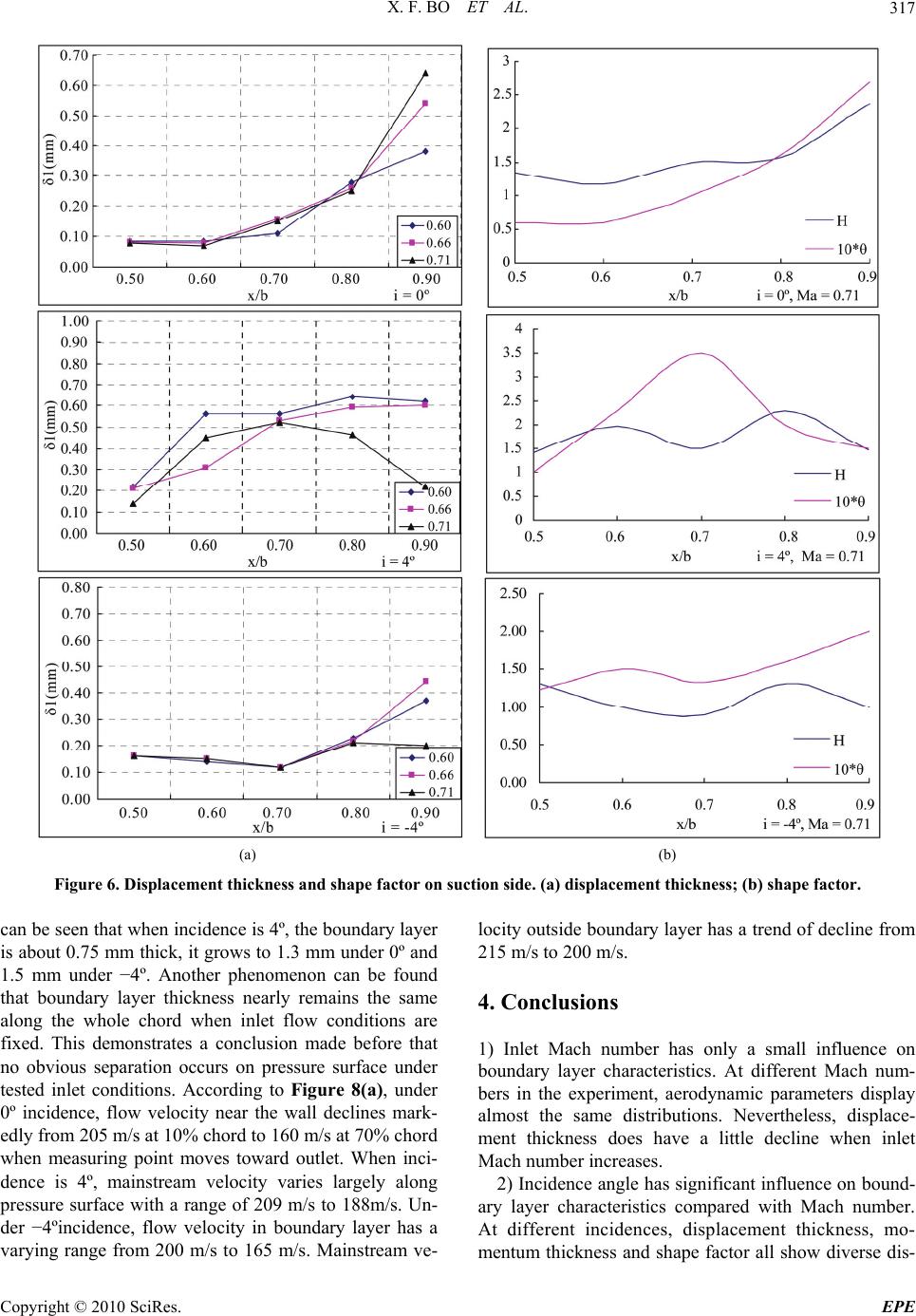 X. F. BO ET AL. Copyright © 2010 SciRes. EPE 317 (a) (b) Figure 6. Displacement thickness and shape factor on suction side. (a) displacement thickness; (b) shape factor. can be seen that when incidence is 4º, the boundary layer is about 0.75 mm thick, it grows to 1.3 mm under 0º and 1.5 mm under −4º. Another phenomenon can be found that boundary layer thickness nearly remains the same along the whole chord when inlet flow conditions are fixed. This demonstrates a conclusion made before that no obvious separation occurs on pressure surface under tested inlet conditions. According to Figure 8(a), under 0º incidence, flow velocity near the wall declines mark- edly from 205 m/s at 10% chord to 160 m/s at 70% chord when measuring point moves toward outlet. When inci- dence is 4º, mainstream velocity varies largely along pressure surface with a range of 209 m/s to 188m/s. Un- der −4ºincidence, flow velocity in boundary layer has a varying range from 200 m/s to 165 m/s. Mainstream ve- locity outside boundary layer has a trend of decline from 215 m/s to 200 m/s. 4. Conclusions 1) Inlet Mach number has only a small influence on boundary layer characteristics. At different Mach num- bers in the experiment, aerodynamic parameters display almost the same distributions. Nevertheless, displace- ment thickness does have a little decline when inlet Mach number increases. 2) Incidence angle has significant influence on bound- ary layer characteristics compared with Mach number. At different incidences, displacement thickness, mo- mentum thickness and shape factor all show diverse dis- 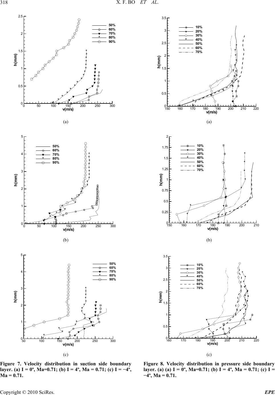 X. F. BO ET AL. Copyright © 2010 SciRes. EPE 318 *********** * * * * * v( m/s) h(mm) 050100 150 200 250 300 0 0.5 1 1.5 2 2.5 50% 60% 70% 80% 90% * (a) ***** ** ***** ** * * * * * * * v(m/s) h( mm) 050100 150200 250 300 0 1 2 3 4 5 50% 60% 70% 80% 90% * (b) * ** **** * * *** * * * * v(m/s) h(mm) 50100 150 200 250 300 0 1 2 3 4 5 50% 60% 70% 80% 90% * (c) Figure 7. Velocity distribution in suction side boundary layer. (a) I = 0º, Ma=0.71; (b) I = 4º, Ma = 0.71; (c) I = −4º, Ma = 0.71. * * * * * * * * * * * * * v( m/ s) h(m m) 150 160 170 180 190 200 210 220 0 0.5 1 1.5 2 2.5 3 3.5 10% 20% 30% 40% 50% 60% 70% * (a) * * * * * * * * * v(m/s) h(mm) 150 160170 180190 200210 0 0.25 0.5 0.75 1 1.25 1.5 1.75 2 10% 20% 30% 40% 50% 60% 70% * (b) * * * * * * * * * * * * * * * v(m/s) h( mm ) 160 170 180 190 200210 220 0 0.5 1 1.5 2 2.5 3 3.5 10% 20% 30% 40% 50% 60% 70% * (c) Figure 8. Velocity distribution in pressure side boundary layer. (a) (a) I = 0º, Ma=0.71; (b) I = 4º, Ma = 0.71; (c) I = −4º, Ma = 0.71. 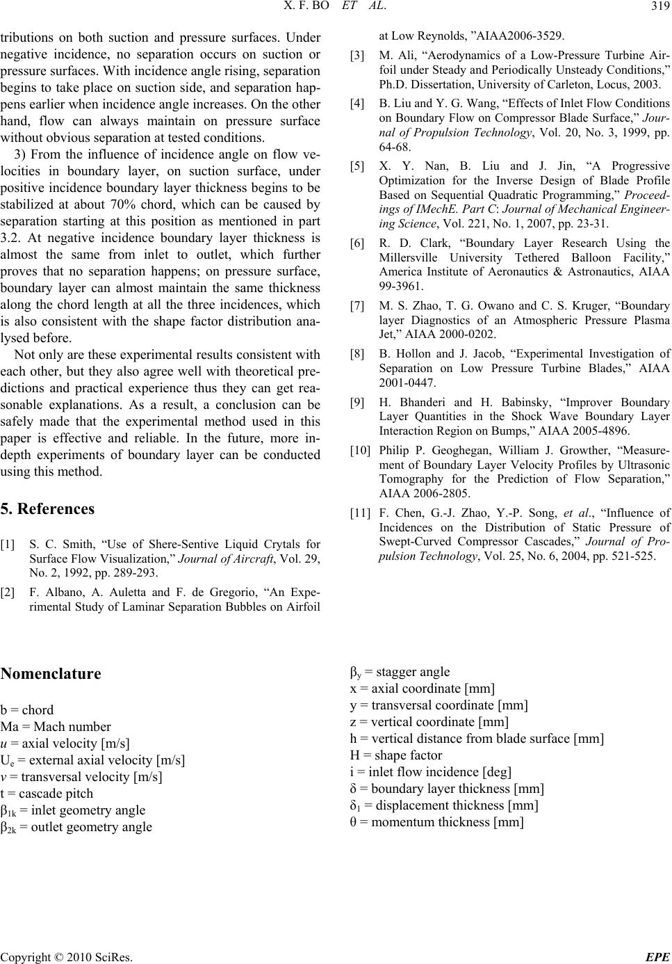 X. F. BO ET AL. Copyright © 2010 SciRes. EPE 319 tributions on both suction and pressure surfaces. Under negative incidence, no separation occurs on suction or pressure surfaces. With incidence angle rising, separation begins to take place on suction side, and separation hap- pens earlier when incidence angle increases. On the other hand, flow can always maintain on pressure surface without obvious separation at tested conditions. 3) From the influence of incidence angle on flow ve- locities in boundary layer, on suction surface, under positive incidence boundary layer thickness begins to be stabilized at about 70% chord, which can be caused by separation starting at this position as mentioned in part 3.2. At negative incidence boundary layer thickness is almost the same from inlet to outlet, which further proves that no separation happens; on pressure surface, boundary layer can almost maintain the same thickness along the chord length at all the three incidences, which is also consistent with the shape factor distribution ana- lysed before. Not only are these experimental results consistent with each other, but they also agree well with theoretical pre- dictions and practical experience thus they can get rea- sonable explanations. As a result, a conclusion can be safely made that the experimental method used in this paper is effective and reliable. In the future, more in- depth experiments of boundary layer can be conducted using this method. 5. References [1] S. C. Smith, “Use of Shere-Sentive Liquid Crytals for Surface Flow Visualization,” Journal of Aircraft, Vol. 29, No. 2, 1992, pp. 289-293. [2] F. Albano, A. Auletta and F. de Gregorio, “An Expe- rimental Study of Laminar Separation Bubbles on Airfoil at Low Reynolds, ”AIAA2006-3529. [3] M. Ali, “Aerodynamics of a Low-Pressure Turbine Air- foil under Steady and Periodically Unsteady Conditions,” Ph.D. Dissertation, University of Carleton, Locus, 2003. [4] B. Liu and Y. G. Wang, “Effects of Inlet Flow Conditions on Boundary Flow on Compressor Blade Surface,” Jour- nal of Propulsion Technology, Vol. 20, No. 3, 1999, pp. 64-68. [5] X. Y. Nan, B. Liu and J. Jin, “A Progressive Optimization for the Inverse Design of Blade Profile Based on Sequential Quadratic Programming,” Proceed- ings of IMechE. Part C: Journal of Mechanical Engineer- ing Science, Vol. 221, No. 1, 2007, pp. 23-31. [6] R. D. Clark, “Boundary Layer Research Using the Millersville University Tethered Balloon Facility,” America Institute of Aeronautics & Astronautics, AIAA 99-3961. [7] M. S. Zhao, T. G. Owano and C. S. Kruger, “Boundary layer Diagnostics of an Atmospheric Pressure Plasma Jet,” AIAA 2000-0202. [8] B. Hollon and J. Jacob, “Experimental Investigation of Separation on Low Pressure Turbine Blades,” AIAA 2001-0447. [9] H. Bhanderi and H. Babinsky, “Improver Boundary Layer Quantities in the Shock Wave Boundary Layer Interaction Region on Bumps,” AIAA 2005-4896. [10] Philip P. Geoghegan, William J. Growther, “Measure- ment of Boundary Layer Velocity Profiles by Ultrasonic Tomography for the Prediction of Flow Separation,” AIAA 2006-2805. [11] F. Chen, G.-J. Zhao, Y.-P. Song, et al., “Influence of Incidences on the Distribution of Static Pressure of Swept-Curved Compressor Cascades,” Journal of Pro- pulsion Technology, Vol. 25, No. 6, 2004, pp. 521-525. Nomenclature b = chord Ma = Mach number u = axial velocity [m/s] Ue = external axial velocity [m/s] v = transversal velocity [m/s] t = cascade pitch β1k = inlet geometry angle β2k = outlet geometry angle βy = stagger angle x = axial coordinate [mm] y = transversal coordinate [mm] z = vertical coordinate [mm] h = vertical distance from blade surface [mm] H = shape factor i = inlet flow incidence [deg] δ = boundary layer thickness [mm] δ1 = displacement thickness [mm] θ = momentum thickness [mm] |