Paper Menu >>
Journal Menu >>
 Energy and Power En gi neering, 2010, 2, 254-261 doi:10.4236/epe.2010.24037 Published Online November 2010 (http://www.SciRP.org/journal/epe) Copyright © 2010 SciRes. EPE Effect of Metal Oxide Arrester on Chaotic Behavior of Power Tr ansformers Ataollah Abbasi1, Mehrdad Rostami1, Seyyed Hamid Fathi2, Hamid R. Abbasi3, Hamid Abdollahi1 1Shahed University, Tehran, Iran 2Amir Kabir University, Tehran, Iran 3Iran University of Science and Technology, Tehran, Iran E-mail: ataollah_abbasi@yahoo.com Received April 28, 2010; revised July 8, 2010; accepted August 16, 2010 Abstract This paper investigates the Effect of Metal Oxide Arrester (MOV) on the Chaotic Behaviour of power trans- formers considering nonlinear model for core loss of transformer. The paper contains two parts. In part (1): effect of nonlinear core on the onset of chaotic ferroresonance in a power transformer is evaluated. The core loss is modeled by a third order power series in voltage. in part (2): Effect of Metal Oxide Arrester(MOV) on results in part (1) will be studied. The results reveal that the presence of the arrester has a mitigating effect on ferroresonant chaotic overvoltages. resulted bifurcation diagrams and phase plane diagrams have also been delivered. Keywords: Chaotic Ferroresonance, MOV, Nonlinear Core Loss, Bifurcation Diagram, Phase Plane Diagram 1. Introduction Ferroresonance is a complex nonlinear electrical phe- nomenon that can cause dielectric and thermal problems to components power system. Electrical systems exhib- iting ferroresonant behaviour are categorized as nonlin- ear dynamical systems. Therefore conventional linear solutions can not be applied to study ferroresonance. The prediction of ferroresonance is achieved by detailed modelling using a digital computer transient analysis program [1]. Ferroresonance should not be confused with linear resonance that occurs when inductive and capaci- tive reactances of a circuit are equal. In linear resonance the current and voltage are linearly related and are fre- quency dependent. In the case of ferroresonance it is characterised by a sudden jump of voltage or current from one stable operating state to another one. The rela- tionship between voltage and current is dependent not only on frequency but also on other factors such as sys- tem voltage magnitud e, initial magnetic flux condition of transformer iron core, total loss in the ferroresonant cir- cuit and moment of switching [2]. Ferroresonance mey be initiated by contingency switching operation, routine switching, or load shedding involving a high voltage transmission line. It can result in Unpredictable over voltages and high currents. The prerequisite for ferrore- sonance is a circuit containing iron core inductance and a capacitance. Such a circuit is characterized by simulta- neous existence of several steady-state solutions for a given set of circuit parameters. The abrupt transition or jump from one steady state to another is triggered by a disturbance, switching action or a gradual change in val- ues of a parameter. Typical cases of ferroresonance are reported in Refs. [4-6]. Theory of nonlinear dynamics has been found to provide deeper insight into the phe- nomenon. Refs. [7-9] are among the early investigations in applying theory of bifurcation and chaos to ferroreso- nance. The susceptibility of a ferroresonant circuit to a quasiperiodic and frequency locked oscillations are pre- sented. in Ref [10]. The effect of initial conditions is also investigated. Ref. [11] is a milestone contribution high- lighting the effect of transformer modeling on the pre- dicted ferroresonance oscillations. Using a linear model. authors of Ref. [12] have indicated the effect of core loss in damping ferroresonance oscillations. The impor- tance of treating core loss as a nonlinear function of voltage is highlighted in Ref. [13]. An algorithm for cal- culating core lo ss from no-load characteristics is given in Ref. [14]. The mitigating effect of transformer with lin- ear core loss model connected in parallel to a MOV ar- rester is illustrated in Ref. [15]. Ferro resonance in ca- pacitive voltage transformer using nonlinear models 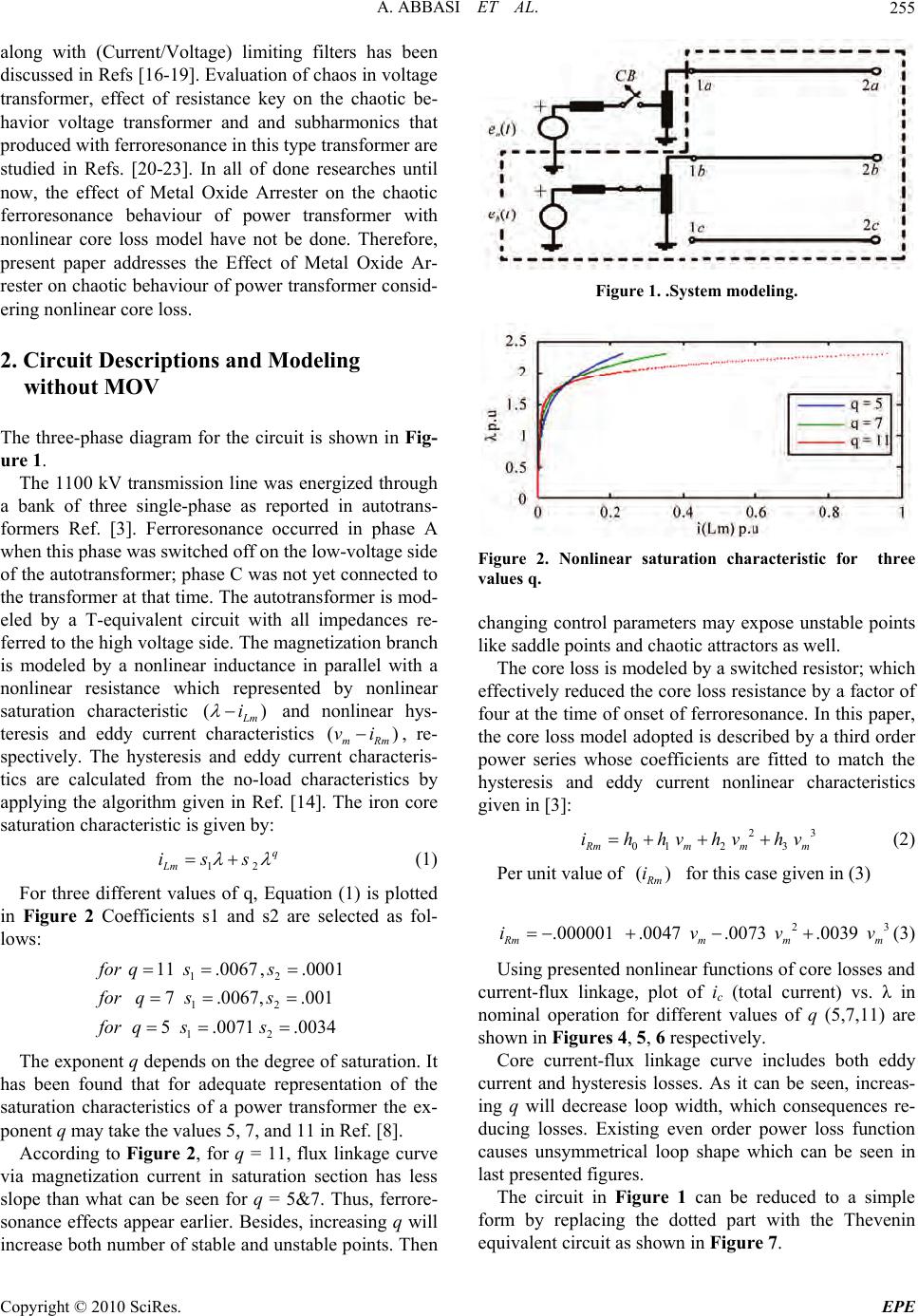 A. ABBASI ET AL. Copyright © 2010 SciRes. EPE 255 along with (Current/Voltage) limiting filters has been discussed in Refs [16-19]. Evalua tion of chaos in voltage transformer, effect of resistance key on the chaotic be- havior voltage transformer and and subharmonics that produced with ferroresonance in this type transformer are studied in Refs. [20-23]. In all of done researches until now, the effect of Metal Oxide Arrester on the chaotic ferroresonance behaviour of power transformer with nonlinear core loss model have not be done. Therefore, present paper addresses the Effect of Metal Oxide Ar- rester on chaotic behav iour of power transformer consid- ering nonlinear core loss. 2. Circuit Descriptions and Modeling without MOV The three-phase diagram for the circuit is shown in Fig- ure 1. The 1100 kV transmission line was energized through a bank of three single-phase as reported in autotrans- formers Ref. [3]. Ferroresonance occurred in phase A when this phase was switched off on the low-voltage side of the autotransformer; phase C was not yet connected to the transformer at that time. The autotransformer is mod- eled by a T-equivalent circuit with all impedances re- ferred to the high voltage side. The magnetization branch is modeled by a nonlinear inductance in parallel with a nonlinear resistance which represented by nonlinear saturation characteristic () L m i and nonlinear hys- teresis and eddy current characteristics () mRm vi, re- spectively. The hysteresis and eddy current characteris- tics are calculated from the no-load characteristics by applying the algorithm given in Ref. [14]. The iron core saturation characteristic is given by: 12 q Lm iss (1) For three different values of q, Equation (1) is plotted in Figure 2 Coefficients s1 and s2 are selected as fol- lows: 12 12 12 11.0067, .0001 7.0067, .001 5.0071 .0034 for qss for qss for qss The exponent q depends on the degree of satur ation. It has been found that for adequate representation of the saturation characteristics of a power transformer the ex- ponent q may take the values 5, 7, and 11 in Ref. [8]. According to Figure 2, for q = 11, flux linkage curve via magnetization current in saturation section has less slope than what can be seen for q = 5&7. Thus, ferrore- sonance effects appear earlier. Besides, increasing q will increase both number of stable and unstable points. Then Figure 1. .System modeling. Figure 2. Nonlinear saturation characteristic for three values q. changing control parameters may expose unstable points like saddle points and chaotic attractors as well. The core loss is modeled by a switched resistor; which effectively reduced the core loss resistance by a factor of four at the time of onset of ferroresonance. In this paper, the core loss model adopted is describ ed by a third order power series whose coefficients are fitted to match the hysteresis and eddy current nonlinear characteristics given in [3]: 23 01 23 Rmm mm ihhvhvhv (2) Per unit value of () R m i for this case given in (3) 23 .000001 .0047 .0073 .0039 R mmmm ivvv (3) Using presented nonlin ear functions of core losses and current-flux linkage, plot of ic (total current) vs. λ in nominal operation for different values of q (5,7,11) are shown in Figures 4, 5, 6 respectively. Core current-flux linkage curve includes both eddy current and hysteresis losses. As it can be seen, increas- ing q will decrease loop width, which consequences re- ducing losses. Existing even order power loss function causes unsymmetrical loop shape which can be seen in last presented figures. The circuit in Figure 1 can be reduced to a simple form by replacing the dotted part with the Thevenin equivalent circuit as shown in Figure 7.  A. ABBASI ET AL. Copyright © 2010 SciRes. EPE 256 Figure 3.V-I characteristic of nonlinear core loss. Figure 4. Core current – Flux linkage curve for q=1 1 wi- tout MOVand nonminal operation. Figure 5. Core current – Flux linkage curve for q = 7 witout MOVand nonminal operation. Transformer data in [3] Eth and Zth are: 130.1 ;1.012430.5 th th EkvzjE The resulting circuit to be investigated is shown in Figure 8 where Zth represents the Thevenin impedance. The behavior of this circuit can be described by the fol- Figure 6. Core current – Flux linkage curve for q = 5 witout MOVand nonminal operation. Figure 7. Thevenin circuit of Figure 1. lowing system of nonlinear differential equations: The behavior of this circuit can be resented by the fol- lowing system of nonlinear differential equations: 23 12 0123 q c ss hhPhPhP pV C (5) With these parameters: .. . 635.1,78.72 ,8067, .0188, .07955, .0014556.68 . basebase base Spu pu pu VKvI AR LC RRcorepu In (4), (5) , P and c V has been taken as state variables as follows: 12 3 ; ; c x xPxV (6) 12 Px x (7) 23 11210122 23 2 3 q s xsx hhxhxhx Px C (9) 23 1 2120123212 2 2 21 23 23 q q th c et V PRssh hPhPhPLsPqsP PLh hPhP (4) 23 1 32 211210122232212212 22 21 2232 23 q q th etxxRsxsxhhxhxhxLsxqsxx Px Lh hxhx (8)  A. ABBASI ET AL. Copyright © 2010 SciRes. EPE 257 2.1. Simulation Results and Discussion for Circuit without MOV Time domain simulations were performed using fourth order Runge_/Kutta method and validated against Matlab Simulink results. The initial conditions derived from steady-state solution of Matlab are: 12 3 0,0 ;1.67;1.55) x xpuxpu The major analytical tools that in this paper are used to study chaotic ferroresonance are Phase Plane and bifur- cation di a gram. The phase plane analysis is a graphical method, in which the time behavior of a system is represented by the movement of state variables of the system in a state space coordination against time. As time evolves, the initial poin t follows a trajectory. If a trajectory closes on itself, then the system produces a periodic solution. In the chaotic system, the trajectory will never close to it- self to shape cycles. A bifurcation diagram is a plot that displays single or multiple solutions (bifurcatio ns) as the value of the control parameter is in creased. Figures 9-11 shows phase plane diagrams of chaotic behaviour for various values of q. The chaotic behaviour has been intensified with in- creasing values of q and this behaviour has been shown in these figures. In Figures 12-14 core current – flux linkage curves in chaotic ferroresonance mode has been shown. Appearing high frequency oscillations, causes loop width wider than normal operation of power transformer for all q values. To study voltage effect on system behavior, system has been enegrgized with different supply voltages. Fig- ures 12-14 show resulted core current-flux linkage curves. All figures are obtained in normal operation of transformer and not in ferroresonance or other abnormal situations. Also Figures 15-17 show the bifurcation dia- gram of chaotic behaviours for these three of values of q. The nonlinear core loss model creats a mitigation on the chaotic ferroresonance behavior in transformer. This Figure 8. Circuit of ferroresonance investigations without MOV. Figure 9. Phase plane diagram for q = 5 without MOV. Figure 10. Phase plane diagram for q = 7 without MOV. Figure 11. Phase plane diagram for q = 11 without MOV. mitigation is due to delaying terms in nonlinear model. Also presence of nonlinear model for core loss in dy- namic equation shows that resulted chaotic ferroreso- nance behavior of system in comparison with the one with linear core loss model, shows that routing to chaos from period doubling will be smother, more regular and also more distinguishable. The hatched area under 1.p.u in bifurcation diagrams are due to transmission lines parameters effects. In Ref [8] results has been simplified by elimination of trans- mission line parameters, which hatched area cannot be seen. 3. Circuit Descriptions and Modeling with MOV The system considered for analysis consists the MOV 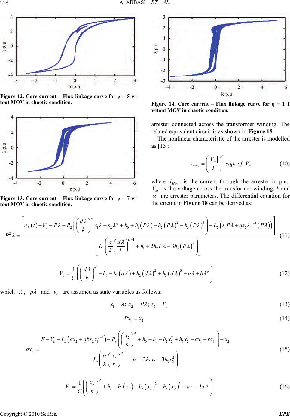 A. ABBASI ET AL. Copyright © 2010 SciRes. EPE 258 Figure 12. Core current – Flux linkage curve for q = 5 wi- tout MOV in chaotic condition. Figure 13. Core current – Flux linkage curve for q = 7 wi- tout MOV in chaotic condition. Figure 14. Core current – Flux linkage curve for q = 1 1 witout MOV in chaotic condition. arrester connected across the transformer winding. The related equivalent circuit is as shown in Figure 18. The nonlinear characteristic of the arrester is modelled as [15]: m M ov m V isignofV k (10) where M ov i, is the current through the arrester in p.u., m V is the voltage across the transformer winding, k and are arrester parameters. The differential equation for the circuit in Figure 18 can be derived as: 23 1 2120123 212 2 12 2123 23 q q th cd et V PRssh hPhPhPLsPqsP k Pd LhhPhP kk (11) 23 01 23 1q cd Vhhdhdhdab Ck (12) which , p and c v are assumed as state variables as follows: 12 3 ; ; c x xPxV (13) 12 Px x (14) 123 2 221 012232112 212 212232 23 qq cs s s x E VLaxqbxxRhhhxhxaxbxx k dx x Lhhxhx kk (15) 23 2012 223211 1q cx Vhhxhxhxaxbx Ck (16)  A. ABBASI ET AL. Copyright © 2010 SciRes. EPE 259 Figure 15. Bifurcation diagram for q = 5 without MOV. Figure 16. Bifurcation diagram for q = 7 without MOV. Figure 17. Bifurcation diagram for q = 11 without MOV. Figure 18. Circuit of ferroresonance investigations with MOV. The numerical param ete rs for M OV is: 25 2.5101k Figures 19, 20, 21 show the time domain simulation phase plane diagram of system states and curve of core current-flux linkage, including arrester for E = 5; The MOV cuts off over voltage so a result of ferrore- Figure 19. Time domain signal for E = 5 and q = 11 With MOV. Figure 20. Phase plane diagram for E = 5 and q = 11 With MOV. Figure 21. Core current – Flux linkage curve for q = 11 while MOV exists in circuit. sonance chaotic unstable trajectory and eliminates chaos greatly. Figures 22, 23, and 24 are the bifurcation diagrams by applying MOV surge arrester that show chaotic region mitigates. The tendency for chaos exhibited by the sys- tem increases while q increases too Refer to Figures 21-24 the MOV in some cases may cause ferroresonace dropout. For q = 5, 7 MOV chaotic condition chang es to periodic behavior in system, but for q = 11 independent chaotic regions which can be created under MOV nominal voltage have survived. Also the pollutions under 1.p.u in bifurcation diagrams due to effect of transmission lines parameters, despite existence of MOV would not be su rvived. 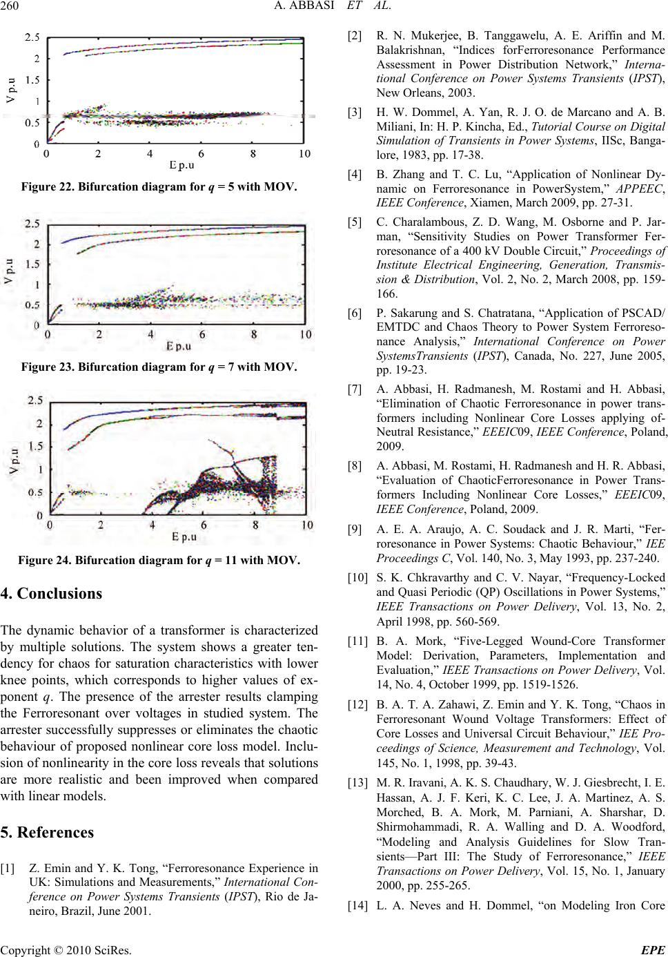 A. ABBASI ET AL. Copyright © 2010 SciRes. EPE 260 Figure 22. Bifurcation diagram for q = 5 with MOV. Figure 23. Bifurcation diagram for q = 7 with MOV. Figure 24. Bifurcation diagram for q = 11 with MOV. 4. Conclusions The dynamic behavior of a transformer is characterized by multiple solutions. The system shows a greater ten- dency for chaos for saturation characteristics with lower knee points, which corresponds to higher values of ex- ponent q. The presence of the arrester results clamping the Ferroresonant over voltages in studied system. The arrester successfully suppresses or eliminates the chaotic behaviour of proposed nonlinear core loss model. Inclu- sion of nonlinearity in the core loss reveals that so lutions are more realistic and been improved when compared with linear models. 5. References [1] Z. Emin and Y. K. Tong, “Ferroresonance Experience in UK: Simulations and Measurements,” International Con- ference on Power Systems Transients (IPST), Rio de Ja- neiro, Brazil, June 2001. [2] R. N. Mukerjee, B. Tanggawelu, A. E. Ariffin and M. Balakrishnan, “Indices forFerroresonance Performance Assessment in Power Distribution Network,” Interna- tional Conference on Power Systems Transients (IPST), New Orleans, 2003. [3] H. W. Dommel, A. Yan, R. J. O. de Marcano and A. B. Miliani, In: H. P. Kincha, Ed., Tutorial Course on Digital Simulation of Transients in Power Systems, IISc, Banga- lore, 1983, pp. 17-38. [4] B. Zhang and T. C. Lu, “Application of Nonlinear Dy- namic on Ferroresonance in PowerSystem,” APPEEC, IEEE Conference, Xiamen, March 2009, pp. 27-31. [5] C. Charalambous, Z. D. Wang, M. Osborne and P. Jar- man, “Sensitivity Studies on Power Transformer Fer- roresonance of a 400 kV Double Circuit,” Proceedings of Institute Electrical Engineering, Generation, Transmis- sion & Distribution, Vol. 2, No. 2, March 2008, pp. 159- 166. [6] P. Sakarung and S. Chatratana, “Application of PSCAD/ EMTDC and Chaos Theory to Power System Ferroreso- nance Analysis,” International Conference on Power SystemsTransients (IPST), Canada, No. 227, June 2005, pp. 19-23. [7] A. Abbasi, H. Radmanesh, M. Rostami and H. Abbasi, “Elimination of Chaotic Ferroresonance in power trans- formers including Nonlinear Core Losses applying of- Neutral Resistance,” EEEIC09, IEEE Conference, Poland, 2009. [8] A. Abbasi, M. Rostami, H. Radmanesh and H. R. Abbasi, “Evaluation of ChaoticFerroresonance in Power Trans- formers Including Nonlinear Core Losses,” EEEIC09, IEEE Conference, Poland, 2009. [9] A. E. A. Araujo, A. C. Soudack and J. R. Marti, “Fer- roresonance in Power Systems: Chaotic Behaviour,” IEE Proceedings C, Vol. 140, No. 3, May 1993, pp. 237-240. [10] S. K. Chkravarthy and C. V. Nayar, “Frequency-Locked and Quasi Periodic (QP) Oscillations in Power Systems,” IEEE Transactions on Power Delivery, Vol. 13, No. 2, April 1998, pp. 560-569. [11] B. A. Mork, “Five-Legged Wound-Core Transformer Model: Derivation, Parameters, Implementation and Evaluation,” IEEE Transactions on Power Delivery, Vol. 14, No. 4, October 1999, pp. 1519-1526. [12] B. A. T. A. Zahawi, Z. Emin and Y. K. Tong, “Chaos in Ferroresonant Wound Voltage Transformers: Effect of Core Losses and Universal Circuit Behaviour,” IEE Pro- ceedings of Science, Measurement and Technology, Vol. 145, No. 1, 1998, pp. 39-43. [13] M. R. Iravani, A. K. S. Chaudhary, W. J. Giesbrecht, I. E. Hassan, A. J. F. Keri, K. C. Lee, J. A. Martinez, A. S. Morched, B. A. Mork, M. Parniani, A. Sharshar, D. Shirmohammadi, R. A. Walling and D. A. Woodford, “Modeling and Analysis Guidelines for Slow Tran- sients—Part III: The Study of Ferroresonance,” IEEE Transactions on Power Delivery, Vol. 15, No. 1, January 2000, pp. 255-265. [14] L. A. Neves and H. Dommel, “on Modeling Iron Core  A. ABBASI ET AL. Copyright © 2010 SciRes. EPE 261 Nonlinearities,” IEEE Transactions on Power Systems, Vol. 8, No. 2, May 1993, pp. 417-425. [15] K. A. Anbari, R. Ramanjam, T. Keerthiga and K. Kup- pusamy, “Analysis of Nonlinear Phenomena in MOV Connected Transformer,” IEE Proceedings - Generation Transmission and Distribution, Vol. 148, No. 6, Novem- ber 2001, pp. 562-566. [16] M. Sanaye-Pasand, A. Rezaei-Zare, H. Mohseni, S. Farhangi and R. Iravani, “Comparison of Performance of Various Ferroresonance Suppressing Methods in Induc- tive and Capacitive Voltage Transformers,” Power India Conference, 2006. [17] A. Rezaei-Zare, M. Sanaye-Pasand, H. Mohseni, S. Farhangi and R. Iravani, “Analysis of Ferroresonance Modes in Power Transformers Using Preisach-Type Hysteretic Magnetizing Inductance,” IEEE Transactions on Power Delivery, Vol. 22, No. 2, April 2007, pp. 919- 929. [18] S. Shahabi and A. Gholami, “Investigation of Perform- ance of Ferroresonance Suppressing Circuits in Coupling Capacitor Voltage Transformers,” ICIEA09, IEEE Con- ference, May 2009, pp. 216-221. [19] M. Graovac, R. Iravani, X. Wang and R. D. M. Taggart, “Fast Ferroresonance Suppression of Coupling Capacitor Voltage Transformers,” IEEE Transactions on Power Delivery, Vol. 18, No. 1, January 2003, pp. 158-163. [20] H. Radmanesh, M. Rostami and A. Abbasi, “Effect of Circuit Breaker Shunt Resistance on Ferroresonance Phe- nomena in Voltage Transformer,” SEC09, IEEE Confer- ence, Athens, 2009. [21] R. G. Kavasseri, “Analysis of Subharmonics Oscillations in a Ferroresonant Circuit,” Electrical Power and Energy Systems, Elsevier Journal, Vol. 28, No. 3, March 2006, pp. 207-214. [22] Z. Emin, B. A. T. A. Zahawi, Y. K. Tong and M. Ugur, “Quantification of the Chaotic Behavior of Ferroresonant Voltage Transformer Circuits,” IEEE Transactions on Circuits and Systems, Fundamental Theory and Applica- tions, Vol. 48, No. 6, June 2001, pp. 757-760. [23] B. A. T. A. Zahawi, Z. Emin and Y. K. Tong, “Chaos in Ferroresonant Wound Voltage Transformers: Effect of Core Losses and Universal Circuit Behaviour,” IEE Pro- ceedings of Science, Measurement and Technology, Vol. 145, No. 1, 1998, pp. 757-760. Appendix: Nomenclature a, b, c index of phase sequence h0, h1, h2, h3, coefficient for core loss nonlinear func- tion n index for the neutral connection s1 coefficient for linear part of magnetizing curve s2 coefficient for nonlinear part of magnetizing curve q Inde x of n onl inearity of the magnet i zi ng curve Zth Thevenin’s equivalent impedance C linear capacitor Rm core loss resistance L nonlinear magnetizing inductance of the trans- former i instantaneous value of branch current v instantaneous value of the voltage across a branch element eth(t) instantaneous value of Thevenin voltage source e instantaneous value of driving source p time derivative operator Eth R.M.S. value of the Thevenin voltage source x state variable λ flux linkage in the nonlinear inductance |

