Paper Menu >>
Journal Menu >>
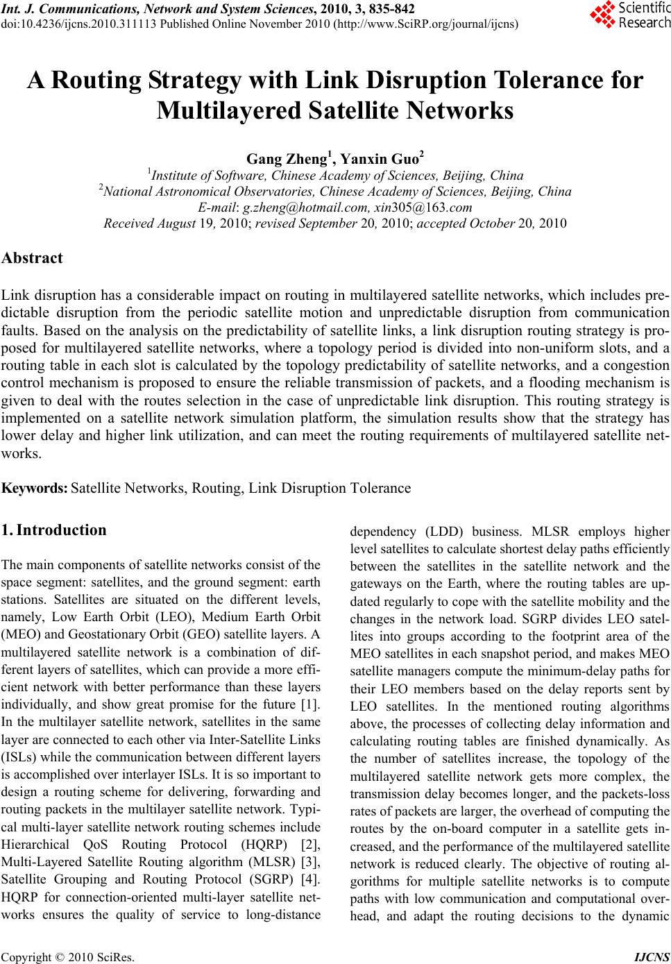 Int. J. Communications, Network and System Sciences, 2010, 3, 835-842 doi:10.4236/ijcns.2010.311113 Published Online November 2010 (http://www.SciRP.org/journal/ijcns) Copyright © 2010 SciRes. IJCNS A Routing Strategy with Link Disruption Tolerance for Multilayered Satellite Networks Gang Zheng1, Yanxin Guo2 1Institute of Software, Chinese Academy of Sciences, Beijing, China 2National Astronomical Observatories, Chinese Academy of Sciences, Beijing, China E-mail: g.zheng@hotmail.com, xin305@163.com Received August 19, 2010; revised September 20, 2010; accepted October 20, 2010 Abstract Link disruption has a considerable impact on routing in multilayered satellite networks, which includes pre- dictable disruption from the periodic satellite motion and unpredictable disruption from communication faults. Based on the analysis on the predictability of satellite links, a link disruption routing strategy is pro- posed for multilayered satellite networks, where a topology period is divided into non-uniform slots, and a routing table in each slot is calculated by the topology predictability of satellite networks, and a congestion control mechanism is proposed to ensure the reliable transmission of packets, and a flooding mechanism is given to deal with the routes selection in the case of unpredictable link disruption. This routing strategy is implemented on a satellite network simulation platform, the simulation results show that the strategy has lower delay and higher link utilization, and can meet the routing requirements of multilayered satellite net- works. Keywords: Satellite Networks, Routing, Link Disruption Tolerance 1. Introduction The main components of satellite networks consist of the space segment: satellites, and the ground segment: earth stations. Satellites are situated on the different levels, namely, Low Earth Orbit (LEO), Medium Earth Orbit (MEO) and Geostationary Orbit (GEO) satellite layers. A multilayered satellite network is a combination of dif- ferent layers of satellites, which can provide a more effi- cient network with better performance than these layers individually, and show great promise for the future [1]. In the multilayer satellite network, satellites in the same layer are connected to each other via Inter-Satellite Links (ISLs) while the communication between different layers is accomplished over interlayer ISLs. It is so important to design a routing scheme for delivering, forwarding and routing packets in the multilayer satellite network. Typi- cal multi-layer satellite network routing schemes include Hierarchical QoS Routing Protocol (HQRP) [2], Multi-Layered Satellite Routing algorithm (MLSR) [3], Satellite Grouping and Routing Protocol (SGRP) [4]. HQRP for connection-oriented multi-layer satellite net- works ensures the quality of service to long-distance dependency (LDD) business. MLSR employs higher level satellites to calculate shortest delay paths efficiently between the satellites in the satellite network and the gateways on the Earth, where the routing tables are up- dated regularly to cope with the satellite mobility and the changes in the network load. SGRP divides LEO satel- lites into groups according to the footprint area of the MEO satellites in each snapshot period, and makes MEO satellite managers compute the minimum-delay paths for their LEO members based on the delay reports sent by LEO satellites. In the mentioned routing algorithms above, the processes of collecting delay information and calculating routing tables are finished dynamically. As the number of satellites increase, the topology of the multilayered satellite network gets more complex, the transmission delay becomes longer, and the packets-loss rates of packets are larger, the overhead of computing the routes by the on-board computer in a satellite gets in- creased, and the performance of the multilayered satellite network is reduced clearly. The objective of routing al- gorithms for multiple satellite networks is to compute paths with low communication and computational over- head, and adapt the routing decisions to the dynamic  836 G. ZHENG ET AL. satellite network topology in real time. As we have known, compared with terrestrial computer networks, satellite networks suffer more significant transmission delay and links disruption from the orbital heights, satel- lites motion, the robustness of links design, space rays, satellites power supply, etc. Therefore, multilayered sat- ellite networks can be seen as delay and disruption tol- erant networks (DTNs) [5]. Recently there has been much research activity in routing problem for DTNs [6]. The delay-tolerant networking routing problem is for- mulated in [7], which amounts to a constrained optimiza- tion problem where edges may be unavailable for ex- tended periods of time and a storage constraint exists at each node. The routing problems in intermittently con- nected ad hoc networks and delay/disruption tolerant networks are discussed in [8], which is categorized as the deterministic case and the stochastic case. A contact- duration-based probabilistic routing scheme is proposed in [9] based on the probabilistic routing scheme. An end-to-end path in DTNs may be unavailable at all times, and routing is performed over time to achieve eventual delivery by employing long-term storage at the interme- diate nodes. As a multilayered satellite network can be thought as a typical DTN case, it is important to investigate the feasi- bility of routing schemes in satellite networks by refer- ring to the routing mechanisms in DTNs. In a multilay- ered satellite network, link disruption mainly consists of two cases: one is predictable because of regular satellites motion around the earth, the other is unpredictable caused by space environment or faults in on-board communication equipments. For the predictable links disruption, routing is computed by predicting the satellite network topology. For the unpredictable case, a routing strategy is required to provide a redundant mechanism to forward packets correctly during links disruption. In this paper, a disruption tolerant routing strategy (DTRS) for a multilayered satellite network is proposed, which combines the statically routing calculation for predictable link state and dynamical link disruption tol- erant mechanism for unpredictable link disruption. In DTRS routing strategy, route tables are calculated by considering the periodical topology of satellite networks caused by the regular motion of satellite and stored in satellites, also, a dynamical congestion control mecha- nism and a flooding-based mechanism are proposed to be tolerant links disruption. This routing strategy is imple- mented in the satellite network simulation platform [10], and the simulation results show that this strategy has lower computation overhead and better performance for links disruption tolerance. 2. Links Prediction Model 2.1. Multilayered Satellite Networks The multilayered satellite network discussed in this paper consists of three layers of satellites, namely, LEO, MEO and GEO satellite layers, as shown in Figure 1. The GEO layer is composed of NG geostationary satellites. The MEO layer is composed of the MEO satellite con- stellation, and the number of satellites is NM. The LEO layer is composed of the LEO satellite constellation, and the number of LEO satellites is NL. In the multilayered satellite network, satellites communicate with the terres- trial gateways over User Data Links (UDLs). A terres- trial gateway can be directly connected to multiple satel- lites in different layers. The type of links includes ISL, IOL and UDL; the ISLs in the same layer are divided into inter-orbit links and inner-orbit links. 2.2. Links Prediction In the multilayered satellite network, the location of a satellite is determined by the Kepler’s laws, in addition, orbit perturbations are considered. A set of six orbital parameters is used to fully describe the position of a sat- ellite in a point in space at any given time: semi-major axis a, eccentricity e, inclination of the orbit plane i, right ascension of the node Ω, the argument of perigee ω, and true anomaly . The links between two satellites are determined by the visibility analysis. Let the position vector of each satellite in the geocen- tric coordinate system be ),,( zyxr , the satellite loca- tion in the geocentric coordinate system can be calcu- lated by the following formula: cos sinsincoscos sin sincoscos cos sin sin xR R yR R zR (1) MEO layer LEO layer GEO layer UDL GEO innerlayer ISL MEO innerlayer ISL LEO innerlayer ISL Interlayer ISL Interlayer ISL ground station Figure 1. Multilayered satellite networks. Copyright © 2010 SciRes. IJCNS  G. ZHENG ET AL. 837 where R orbital enote the distance from the earth center O to th a ) 0h: is a satellite orbit radius; α is a satellite inclination; β= iπ/n is the angle between the positive axle of y and the intersection line of satellite orbit plane and equatorial plane, n is a track number, i is a track sequen- tial number. Let γ denote the satellite-phase at the time instant t, γ = ωt + γ0, where ω is the angular velocity, γ0 is the initial phase. The above parameters are shown in the Figure2. Let h d e line connecting satellite1 and satellite 2. In order to compute the visibility between two satellites in the mul- tilayered satellite network, define the visibility function Δh = h − Re, where Re is the redius of the earth, the visi- bility condition is given as follows: 12 21 sin rr rr h , where 21 21 )( arccos rr rr is the angle between the two satellite geocentric position how vector. Let H denote the minimum visible height be- tween two satellites. If hH , two satellites are visi- ble. This visible relation is sn in Figure 3(a). b) 0h: Let be the angle between r and 21 rr , if 11 2 11 2 () arccos 90 rrr rrr If the position relation between two satellites satisfies , the two s are visible. This visible relation is shown in Figure 3(b). th . Disruption Tolerant Routing Strategy ompared with the terrestrial networks, particularly op- satellite e visibility conditions, two satellites can communicate with each other over interstellar links. 3 C tical networks, the multilayered satellite network suffers long propagation delay, relative high bit error rate and limited bandwidth, in addition, relatively frequent links disruption. The disruption of links in the satellite net- work is caused by the motion of satellites, faults in communication subsystems, power supply, space envi- ronments, etc. The routing strategy for the satellite net- work must be tolerant of such constraints as long delay, links disruption, available power. In order to save the power supply and computation ability, a routing strategy is proposed based on the idea combining the static rout- ing and dynamic routing. In terms of cyclic motion of satellites, the topology of the satellite network changes regularly, thus the routing table is calculated on the basis of the regularity and predictability of satellite motion and stored in a satellite before satellites are launched. When calculating the routing table, the real time requirements of different kinds of traffic in the satellite network, transmission delay caused long distance and the more number of hops in the lower satellite network, are con- sidered. The propagation delay and queuing delay are defined as two weights of a link, in addition, a mecha- nism to limit the number of hops is employed to make comprise between the number of hops and the transmis- sion delay. For the unpredictable link disruption caused communication faults or other reason, a flooding mecha- nism is proposed to guarantee the routing service. Figure 2. Satellite location in the geocentric coordinate sys- tem. satellite 2 satellit e1 1 r Re Center of earthO earth Re 2 r 12 rr h φ (a) satellit e 2 satellite1 e Rhh Re Center of earth O earth Re 2 r 21 rr h φ (b) Figure 3. (a) Satellites visibisis: Δh > 0; (b). Satel- lites visibility analysis: Δh < 0. lity analy Copyright © 2010 SciRes. IJCNS  G. ZHENG ET AL. 838 etwork shows 3.1. Topology Periods Discretization T d he topology of the multilayered satellite n ynamic and periodic changes. If the topology period is divided into some slots, where each slot is an interval of a stable topology, i.e., a snapshot, it is feasible to design the routing strategy in a slot. The partition in one topol- ogy period is so important, and must not only reflect the dynamic topology timely, but also set appropriate length of each interval. The topological dynamics characteriza- tion for layered satellite network is investigated in [11]. In this paper, the partition of one topology period is computed by the satellite motion and visibility condition in Subsection 2.2. In every snapshot, a routing table is computed and stored in the onboard computer of a satel- lite. Note that the length of each slot is not equal. Let T denote one topology period of the satellite network, if the period is divided into n slots, [t0, t1], [t1, t2], , [tn−1, tn], a discrete time sequence is got, which is denoted as },,,,,{ 1210 nnT tttttS . The topology change happens at the time instants 12 ,, , n tt t, which means that, at the ith time instant ti in oneriod, there must one or more links are connected or disrupted. However, during the ith in- terval 1 [, ] ii tt , the satellite network topology is mapped to a static topology, which is the base of computing the optimal routes. Let graph G(t) = (V, E(t)) denote the sat- ellite network topology with system period T at time t, 0 ≤ t ≤ T , where V is the set of satellite nodes and E(t) is the set of satellite links at t. In order to execute the dis- cretization process, a topology period T is divided into a group of equal intervals. The discretization process is presented as follows: 1) Initialize the discrete pe time sequence set T S an e time instants set T of links connecting or disruptin d th Path Selection obtained portant to ensure the low delay of g; 2) Based on the visibility computation in Subsection 2.2, compute the time instants at which the topology changes and link connections or disruptions happen, and add the time instants into the set T. Arrange the elements in T by time and obtain the dis- crete sequence {,,, }Sttt. 01Tn 3.2. Optimal, Suboptimal For each time instant in the discrete sequence ST in Subsection 3.1, the state of a link in the multilayered satellite network can be computed and predicted. Thus, the entire network topology in each time instant can be obtained, moreover, the on/off status and the length of each link are known. In the DTRS, all satellites in the network are treated equally, and the optimal path at each time instant of ST is calculated based on the instantane- ous network topology. Since most of satellite network services have real time requirements, it is so im data forwarding. When computing the route in the DTRS, a link propagation delay is a main weight so that the delay on the optimal path is the shortest. In addition, because of the motion of satellites, long data forwarding delay may cause link disruption, therefore, a link main- taining time as another weight must be considered. Note that the processing delay and the queuing delay of satel- lites will increase as the number of hops in the route is increased, a compromise must be made between the number of hops and transmission delay. If the number of hops in the route is too much via the lower layer satellite links, it will be more fast and reliable for the data trans- mission to choose another routing path via interstellar links on the higher layer. In the DTRS, an appropriate queuing delay and the limit to the number of hops are given to be as weights of a link to compute the optimal path in the multilayer satellite network. Suppose in a period of the satellite network topology, a link s d I SL between the satellite s an ppens N on/off switches. At the time instant t, the maintaie of d the satellite d ha ning tim s d I SL is defined as off onoff () ,()() () sd sd sd tkttkttk Tt 0,others sd (2) where , denote the link betwe satellite d establishes, disconnects at on () sd tk s tim off () sd tk and the satellite e respectively, en the the k-th 0,1,,kN. Consider a transmission path in the multilayer satellite network 12 (, ,, ) n pss s , where s denotes the i-th sa i tellite node in the path p, i = 1,,n. The path p con- sists of s, 12 inter-satellite link s s ISL , 23 s s ISL , …, 1nn s s ISL , where 1ii s s ISL denote link between the satellite i and the satellite i + ,. The the path ped as s a , i =1 1,n − 1 weight of is defin 1 11 11 12 () () () nn iDISL Ds Wp ww TT 11 ii ii ii ss ii ss ss (3) where D(si) denotes the queue processing dela satellite node s, and denotes a propaga- y on the i1ii ss tion delay of the link ()DISL 1ii s s ISL , w1 and w2 are coeffi- cients, 12 1ww . Given the definition of the th weight, for each time instant ibsection 3. pa n ST of Su1, the optimal path with the shortest delay can be selected based on the Dijkstra algo- rithm from the path set 12 () { (),(),,()} n Ptp tptpt between the source satellite s and the sink satellite d, where pi(t) denotes the ith and the satellite d, i = 1, , n. The optimal path between s and d is path between the satellite s Copyright © 2010 SciRes. IJCNS  G. ZHENG ET AL. Copyright © 2010 SciRes. IJCNS 839 (4) where * * (),s.t.(())min{((),()()}(( ())) (),(())min{((),()()}(( ())) ii i ii i W ptWptp tPtH pth ptWptWptptPtHpth (),if () sd pt pt pt (()) i H pt * is the li is the number of hops for the i-th path p(t), hmit to the number of hops, in this paper, t is set to When computing the sub-optimal path, all links othe optimal path are removed from the satellite networto- 3.3. Conism packets may xperience a relatively long time before they arrive at the i the limi 4. Assume the optimal path from the source satellite s to the sink satellite d is 112 23344 (){(,),(,),( ,),(,),( ,)} sd pt sssssssssd . n k pology, thus a new network topology is obtained, and the sub-optimal path is the optimal path in the new topology graph. If the new path set in the new network topology is 12 () { (),(),,()} m Ptptp tpt , the sub-optimal path () sd pt is shown in Equation (5). ngestion Control Mecha In the multilayered satellite network, data e sink satellite. In the DTRS, the next hop is obtained based on the packets arrival time and the sink satellite, which can ensure the continuity and correctness of data transmission. If the traffic load on a satellite link in- creases too fast, the congestion in the link may occur [5]. In this paper, in order to determine whether the conges- tion has happened or not, the queue occupancy in the output port of a satellite is monitored. Define the queue idle ratio of a satellite output port as 1U RT (6) where U denotes the length o the total queue length. queue. Note that U can be set ba f the occupied queue, T is Let be the congestion threshold and U0 be the mini- mum length of the idle0 sed on the network traffic throughput. If there exists a link in the satellite network subjects to R, it is shown that the traffic in this link increases so quickly. Note that a link disruption can cause the queue idle ratio R of the link is large, therefore a link-state reporting mechanism must be used to determine whether the link is disrupted, moreover it can be determined whether the congestion or the disruption occurs in the link. If a link subjects to R and the link is not disrupted by the reporting mechanism, the congestion occurs in this link. Then the fong-up packets will be routed to the gested, the queue idle ratio of this link will be selected dynamically. The selection process is given as follows: 1) Via the link-state report mechanism, obtain all neighboring satellites set 12 (){ ,,,} Am Ss sss of sat- llowi sub-optimal path to ease the congestion link to the next hop in the sub-optimal path is still con- el in the link. If the lite s at the current time instant, where i s s sISL , i s s ISL is the congested link in the sub-optim ompute the maximum queue idle ratio Rnext of ghboring satellites, and select the correspondi al path. 2) Call the neing satellite snext, that is next arg max{()}1,, iA ii sS s Rs im (7) 3) If Rnext = 1, the data packets is routed , else the data packets is hanged to the queue of uptionolerant Mechanism e queue idle tio to the link next ss ink ISL the lnext ss ISL . 3.4. Disr T As mentioned in the Subsection 3.3, if th R ra in a link of the satellite network and the g mec acket arrives at the satel- lit link is determined to be disrupted via the link-state re- portinhanism, then the link disruption is caused by a fault in the satellite, which is not predictable. In the DTRS, a disruption tolerant mechanism uses a technique known as flooding to deal with the routing selection. The process is presented as follows: 1) For a packet sent from the source satellite to the sink satellite, suppose at tk, the p e s. If the disruption of the link to the next hop satellite 1 (()) ss k s pt in the optimal path happens and the disrup- tion of the link to the next hop satellite 1 (()) ss k s pt in al path happens, the flooding is activated. 2) Based on the link state reporting mall neighboring satellites at tk is obtained, denoted by the se the sub-optim echanism, t 12 (){ ,,,} Am s sssS , i s s ISL . 3) The satellite s sends the flooding message to all the neighboring satellites te table. If the routing is success- fu (5) . 4) On receiving the flooding message, the neighboring satellite si query its rou l, a successful response message is sent back to the satellite s, otherwise, the satellite si starts the flooding process. ( ),( )t pt ( ),if( ),s.t.(())min{(ptpt WptW * * ( )}((( ))) () (),(())min{((),()()}((())) ii i sd ii i pPtHpt h pt ptWptWptptPtHpth  G. ZHENG ET AL. 840 5) The flooding routing process is completed when a satellite, which starting flooding, receives the first suc- cessful response message, moreover, if it has the upper ooding sponsor, it should send successful response m she above, the routing strategy must be ng delay, and limited ard computer in the ultilayered satellite network. In order to evaluate the delay roposed cheLSR scheme, and the simulation time 1440 minutes. The simulation results are presented as Satellite Layers In the simulation scenario, 300 pairs of users distrib- uting uniformly in the globe send multilayered satellite network. The traffic model subjects to the Poisson distribution. The result of the end-to-end a shown in Figure 4. In thh satellite is treated equally; the propagation delay and the ty play ain weights. HoweLSR, thetest paors on ater than the one of the Mhown in Figure 7, both the DTRS an fl essage back to the upper sponsor, however, if all the messages it received are failure response, a failure re- sponse message will be sent back to the upper sponsor. 4. Routing Simulation and Performance Evaluation 4.1. Simulation Configuration mentioned in tA adapted to the dynamic topology, lo processing capability of the on-bo m performance of the routing strategy proposed in the pa- per, the simulation is made on the satellite network simulation platform. Note that the simulation platform is constructed based on the HLA/RTI framework, and can configure scenarios of satellite networks flexibly to test, verify and validate the key technology of satellite net- works. A multilayered satellite network scenario is con- figured in this simulation platform, which consists of LEO, MEO and GEO satellites, as shown in Table 1. 4.2. Simulation Results and Performance Evaluation In the simulation, we compared the end-to-end difference and the cost difference between the p me and the Ms is follows. 1) End-to-end average delay Table 1. Satellite orbital parameters. Parameters LEO GEO MEO Number of Satellites 3 10 48 Orbital 35786 10355 1400 ee) 1 ype Geostationary W Height(Km) Orbital Inclination(degr0 45 52 Orbital Cycle 24 h 6 h 14 min Number of Orbits 1 2 8 Constellation Torbit alker delta Walker delta and receive data by the verage delay ise DTRS, eac ransmission dela ver, in the M critical role the link shorth algithm i ly used within the satellite cluster in each layer; there- fore, the end-to-end average delay in the DTRS is smaller than that in the MLSR. 2) Link utilization Link utilization is compared between the DTRS and the MLSR, which includes three cases as follows. a) Link utilization within the individual layer. Figures 5-7 give the link utilization within the LEO layer, MEO layer, and GEO layer, respectively. Figures 5-6 show that the link utilization within the LEO layer and MEO layer of the DTRS is much gre LSR. However, as s d the MLSR have similar link utilization within the GEO layer. 0 Figure 4. End-to-end average delay. Figure 5. Link utilization within the LEO layer. Copyright © 2010 SciRes. IJCNS  G. ZHENG ET AL. 841 Figure 6. Link utilization within the MEO layer. Figure 7. Link utilization within the GEO layer. b) Link utilization of inter layers. Figures 8-10 give the interlayer link utilization of the LEO-MEO, MEO-GEO, and LEO-GEO, respectively. It can be seen that the interlayer link utilization of the DTRS is greater than the one in the MLSR. It can be concluded from the above simulation results that the end-to-end average delay of can meet the maxi- mum delay requirements of voice service (< 100 ms), and the DTRS routing strategy can be used to forward voice data packets in multi-layer satellite networks. Meanwhile, because of the relative balanced link utiliza- tion in the whole network, the DTRS strategy can reduc the o Note that the time and space complexity of the DTRS s e ccurrence probability of bottleneck links. i relatively low compared with other routing schemes. In the DTRS, the time complexity mainly includes two parts, one is the time of the topological prediction and the other is the time of selecting route, both of which are 2 ()ON, where N is the number of satellites, however, for the onboard routing algorithm, e.g., Bellman algo- hm, the average time complexity is (log)ONN , and the maximum time complexity is 3 ()ON under the ex- treme case. The space complexity of the DTRS is (( 1)) t OK N rit , where Kt is the number of discrete time segments, however, the other routing mechanisms need a network connectivity metric of 2 ()ON and a route ta- ble of ()ON . Figure 8. Link utilization of the inte (LEO-MEO). rlayer Figure 9. Link utilization of the inteMEO-GEO). rlayer ( Figure 10. Link utilization of the interlayer (LEO-GEO). Copyright © 2010 SciRes. IJCNS  G. ZHENG ET AL. Copyright © 2010 SciRes. IJCNS 842 . Conclusion In this paper, a routing strategy with links disruption tolerance is proposed for multilayered satellite networks, which employs the predictability of topology to compute the optimal route in each slot, and a dynamical conges- tion control mechanism is designed to balance the traffic load and ensure the reliability of packets transmission, and a flooding mechanism to process the routing selec- tion is presented for the unpredictable links disruption. This routing strategy is verified on the satellite network simulation platform, and the simulation shows that t proposed strategy has better performance in terms of delay and link utilization and can support routing in mul- t nd M. D. Bender, “MLS Novel Routing Algorithm for Multilayered Satellite IP ll and R. Patra, “Routing in a Delay Toler- elay Tolerant d M. T. Zhou, 5 [4] pp. he Issue on Delay and Disruption Tolerant Wireless Com- munication, Vol. 26, No.5, 2008, pp.820-827. [6] S. Farrell and V. Cahill, “Delay- and Disruption-Tolerant Networking,” Artech House, Boston, 2006. [7] S. Jain, K. Fa ilayered satellite networks efficiently. . Acknowledgements 6 The work was supported by the Knowledge Innovative Foundation of Chinese Academy of Sciences. The au- thors wish to thank anonymous referees for their sugges- tions for improving this paper. 7. References [1] Z. L. Sun, “Satellite Setworking: Principles and Proto- cols,” John Wiley & Sons Press, Hoboken, 2005. [2] J. Lee and S. Kang, “Satellite over Satellite(SOS) Network: A Novel Architecture for Satellite Network,” Proceedings of the IEEE INFOCOM, Tel Aviv, Vol.1, 2000, pp. 315-321. [3] I. F. Akyildiz, E. Ekici aR: A Networks,” IEEE/ACM Transactions on Networking, Vol. 10, No. 3, 2002, pp. 411-424. C. Chen, E. Ekici and I. F. Akyildiz, “Satellite Grouping and Routing Protocol for LEO/MEO Satellite IP Net- works,” Proceedings of the 5th ACM International Workshop on Wireless Mobile Multimedia, Atlanta, 2002, 109-116. [5] C. Caini, P. Cornice, R. Firrincieli and D. Lacamera, “A DTN Approach to Satellite Communications,” IEEE Journal on Selected Areas in Communications, Special ant Network,” IEEE SIGCOMM, 2004, pp.145-148. [8] Z. Zhang, “Routing in Intermittently Connected Mobile Ad Hoc Networks and Delay Tolerant Networks: Over- view and Challenge,” IEEE Communications Surveys & Tutorials, Vol. 8, No. 1, 2006, pp. 24-37. [9] C. S. Lin, W. S. Chang, L. J. Chen and C. F. Chou, “Per- formance Study of Routing Schemes in D Networks,” Proceedings of IEEE AINAW, Okinawa, March 2008, pp. 1702-1707. [10] Y. Xu and G. Zheng, “Modeling and Distributed Simula- tion of Satellite Networks,” Computer Simulation, Vol. 25, No. 2, 2008, pp. 65-69. [11] J. F. Wang, Y. M. Hu, H. X. Zhou an “Topological Dynamics Characterization for Layered Sat- ellite Networks,” Proceedings IEEE Conference Per- formance, Computing and Communications, Phoenix, April 2006, pp. 349-356. |