Paper Menu >>
Journal Menu >>
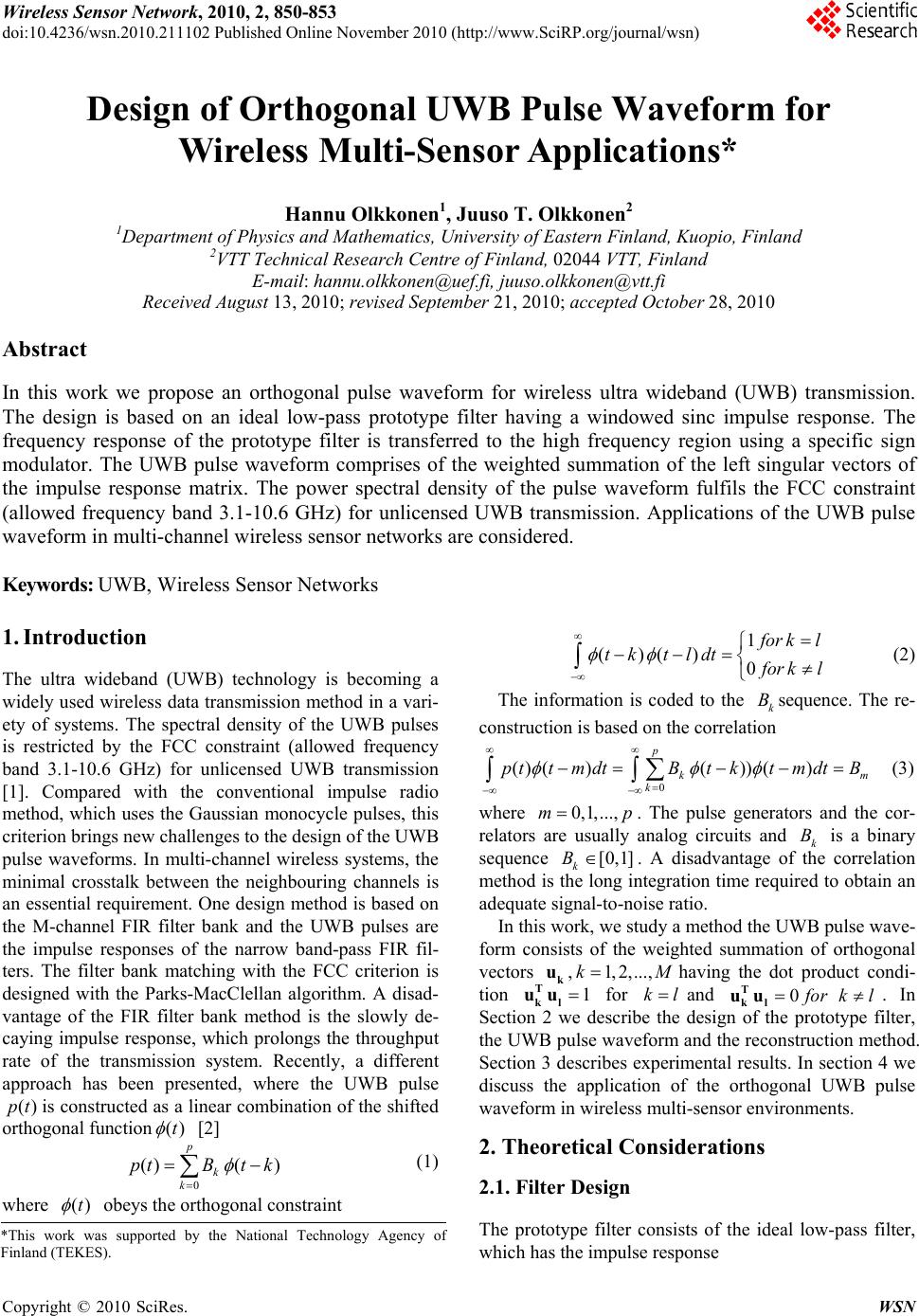 Wireless Sensor Network, 2010, 2, 850-853 doi:10.4236/wsn.2010.211102 Published Online November 2010 (http://www.SciRP.org/journal/wsn) Copyright © 2010 SciRes. WSN Design of Orthogonal UWB Pulse Waveform for Wireless Multi-Sensor Applications* Hannu Olkkonen1, Juuso T. Olkkonen2 1Department of Physics and Ma thematics, University of Eastern Finland, Kuopio, Finlan d 2VTT Technical Research Centre of Finland, 02044 VTT, Finland E-mail: hannu.olkkonen@uef.fi, juuso.olkkonen@vtt.fi Received August 13, 2010; revised September 21, 2010; accepted Octo be r 28, 2010 Abstract In this work we propose an orthogonal pulse waveform for wireless ultra wideband (UWB) transmission. The design is based on an ideal low-pass prototype filter having a windowed sinc impulse response. The frequency response of the prototype filter is transferred to the high frequency region using a specific sign modulator. The UWB pulse waveform comprises of the weighted summation of the left singular vectors of the impulse response matrix. The power spectral density of the pulse waveform fulfils the FCC constraint (allowed frequency band 3.1-10.6 GHz) for unlicensed UWB transmission. Applications of the UWB pulse waveform in multi-channel wireless sensor networks are considered. Keywords: UWB, Wireless Sensor Networks 1. Introduction The ultra wideband (UWB) technology is becoming a widely used wireless data transmission method in a vari- ety of systems. The spectral density of the UWB pulses is restricted by the FCC constraint (allowed frequency band 3.1-10.6 GHz) for unlicensed UWB transmission [1]. Compared with the conventional impulse radio method, which uses the Gaussian monocycle pulses, this criterion brings new challenges to the design of the UWB pulse waveforms. In multi-channel wireless systems, the minimal crosstalk between the neighbouring channels is an essential requirement. One design method is based on the M-channel FIR filter bank and the UWB pulses are the impulse responses of the narrow band-pass FIR fil- ters. The filter bank matching with the FCC criterion is designed with the Parks-MacClellan algorithm. A disad- vantage of the FIR filter bank method is the slowly de- caying impulse response, which prolongs the throughput rate of the transmission system. Recently, a different approach has been presented, where the UWB pulse ()pt is constructed as a linear combination of the sh ifted orthogonal function()t [2] 0 ()( ) p k k ptBt k (1) where ()t obeys the orthogonal constraint 1 ()() 0 f or kl tk tldt f or kl (2) The information is coded to the k Bsequence. The re- construction is based on th e correlation 0 () ()()) () p km k pttmdtBt kt mdtB (3) where 0,1,...,mp . The pulse generators and the cor- relators are usually analog circuits and k B is a binary sequence [0,1] k B . A disadvantage of the correlation method is the long integration time required to obtain an adequate signal-to-noise ratio. In this work, we study a method the UWB pulse wav e- form consists of the weighted summation of orthogonal vectors k u,1,2,...,kM having the dot product condi- tion 1 T kl uu for kl and 0 f or kl T kl uu . In Section 2 we describe the design of the prototype filter, the UWB pulse waveform and the reconstruction method. Section 3 describes experimental results. In section 4 we discuss the application of the orthogonal UWB pulse waveform in wireless multi-sensor environments. 2. Theoretical Considerations 2.1. Filter Design The prototype filter consists of the ideal low-pass filter, which has the impulse response *This work was supported by the National Technology Agency o f Finland (TEKES). 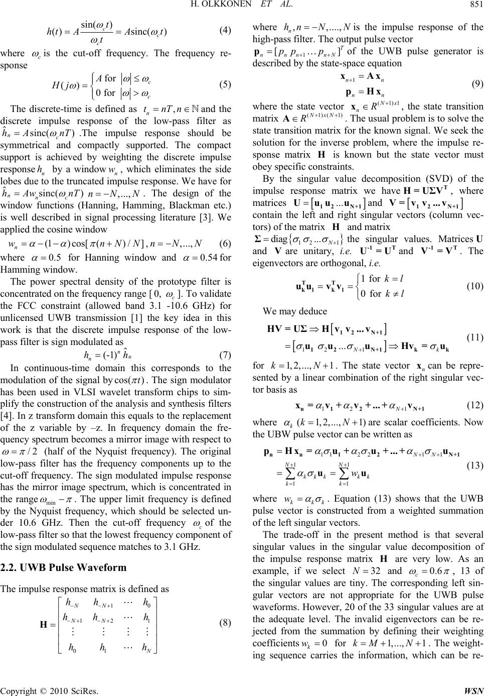 H. OLKKONEN ET AL. Copyright © 2010 SciRes. WSN 851 sin( ) ()sinc() cc c t ht AAt t (4) where c is the cut-off frequency. The frequency re- sponse for () 0 for c c A Hj (5) The discrete-time is defined as , n tnTnand the discrete impulse response of the low-pass filter as sinc( ) nc hA nT .The impulse response should be symmetrical and compactly supported. The compact support is achieved by weighting the discrete impulse response n h by a windown w, which eliminates the side lobes due to the truncated impulse response. We have for sinc() nnc hAw nT ,...,nNN . The design of the window functions (Hanning, Hamming, Blackman etc.) is well described in signal processing literature [3]. We applied the cosine window (1)cos[() /] n wnNN ,,...,nNN (6) where 0.5 for Hanning window and 0.54 for Hamming window. The power spectral density of the prototype filter is concentrated on the frequency range [0, c ]. To validate the FCC constraint (allowed band 3.1 -10.6 GHz) for unlicensed UWB transmission [1] the key idea in this work is that the discrete impulse response of the low- pass filter is sign modulated as (-1)nn n hh (7) In continuous-time domain this corresponds to the modulation of the signal bycos( )t . The sign modulator has been used in VLSI wavelet transform chips to sim- plify the construction of the analysis and synthesis filters [4]. In z transform domain this equals to the replacement of the z variable by –z. In frequency domain the fre- quency spectrum becomes a mirror image with respect to /2 (half of the Nyquist frequency). The original low-pass filter has the frequency components up to the cut-off frequency. The sign modulated impulse response has the mirror image spectrum, which is concentrated in the rangemin . The upper limit frequency is defined by the Nyquist frequency, which should be selected un- der 10.6 GHz. Then the cut-off frequency c of the low-pass filter so that the lowest frequency component of the sign modulated sequence matches to 3.1 GHz. 2.2. UWB Pulse Waveform The impulse response matrix is defined as 10 12 1 01 NN NN N hh h hh h hh h H (8) where , ,...., n hn NN is the impulse response of the high-pass filter. The output pulse vector 1 [] T nnn nN pp p pof the UWB pulse generator is described by the state-space equation 1nn nn xAx pHx (9) where the state vector (1)1 N x nR x, the state transition matrix (1)(1)NxN R A. The usual problem is to solve the state transition matrix for the known signal. We seek the solution for the inverse problem, where the impulse re- sponse matrix H is known but the state vector must obey specific constraints. By the singular value decomposition (SVD) of the impulse response matrix we haveT H=UΣV, where matrices ...12 N+1 Uuuu and 12 N+1 V=v v ...v contain the left and right singular vectors (column vec- tors) of the matrix H and matrix 12 1 diag... N Σthe singular values. MatricesU and Vare unitary, i.e. -1 T U=Uand -1 Τ V=V. The eigenvectors are orthogonal, i.e. 1 for 0 for kl kl TT kl kl uu vv (10) We may deduce 12 1 ... Nk 12 N+1 12N+1k k HV = UΣHvv...v uuu Hv=u (11) for 1,2,..., 1kN . The state vector n xcan be repre- sented by a linear combination of the right singular vec- tor basis as 12 1N n12 N+1 x=v+v+ ... +v (12) where (1,2,...,1) kkN are scalar coefficients. Now the UBW pulse vector can be written as 112 211 11 11 NN NN kkkkk kk w nn 12N+1 pH x=u+u+ ... +u uu (13) where kkk w . Equation (13) shows that the UWB pulse vector is constructed from a weighted summation of the left singular vectors. The trade-off in the present method is that several singular values in the singular value decomposition of the impulse response matrix H are very low. As an example, if we select 32N and 0.6 c , 13 of the singular values are tiny. The corresponding left sin- gular vectors are not appropriate for the UWB pulse waveforms. However, 20 of the 33 singular values are at the adequate level. The invalid eigenvectors can be re- jected from the summation by defining their weighting coefficients 0 k w for 1,..., 1kM N . The weight- ing sequence carries the information, which can be re- 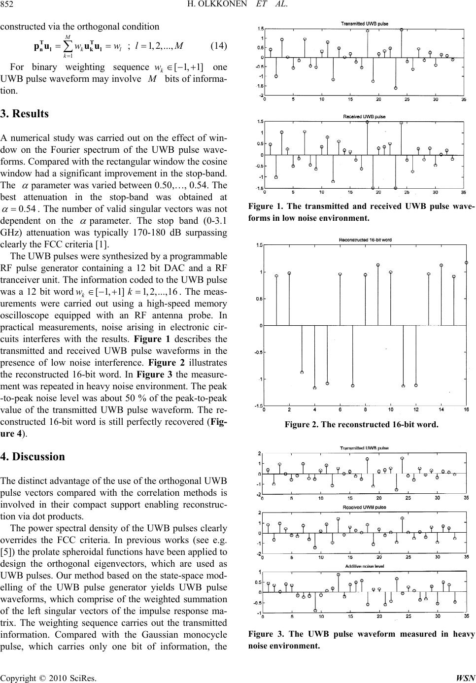 H. OLKKONEN ET AL. Copyright © 2010 SciRes. WSN 852 constructed via the orthogonal condition 1; 1,2,..., M kl k wwl M TT nl kl pu uu (14) For binary weighting sequence[1,1] k w one UWB pulse wavefo rm may in volve M bits of informa- tion. 3. Results A numerical study was carried out on the effect of win- dow on the Fourier spectrum of the UWB pulse wave- forms. Compared with the rectan gular window the cosin e window had a significant improvement in the stop-band. The parameter was varied between 0.50,…, 0.54. The best attenuation in the stop-band was obtained at 0.54 . The number of valid singular vectors was not dependent on the parameter. The stop band (0-3.1 GHz) attenuation was typically 170-180 dB surpassing clearly the FCC criteria [1]. The UWB pulses were synthesized by a program m a ble RF pulse generator containing a 12 bit DAC and a RF tranceiver unit. The information coded to the UWB pulse was a 12 bit word[1,1] k w 1,2,..., 16k. The meas- urements were carried out using a high-speed memory oscilloscope equipped with an RF antenna probe. In practical measurements, noise arising in electronic cir- cuits interferes with the results. Figure 1 describes the transmitted and received UWB pulse waveforms in the presence of low noise interference. Figure 2 illustrates the reconstructed 16-bit word. In Figure 3 the measure- ment was repeated in heavy noise environment. The peak -to-peak noise level was about 50 % of the peak-to-peak value of the transmitted UWB pulse waveform. The re- constructed 16-bit word is still perfectly recovered (Fig- ure 4). 4. Discussion The distinct advantage of the use of the orthogonal UWB pulse vectors compared with the correlation methods is involved in their compact support enabling reconstruc- tion via dot products. The power spectral density of the UWB pulses clearly overrides the FCC criteria. In previous works (see e.g. [5]) the prolate spheroidal functions have been applied to design the orthogonal eigenvectors, which are used as UWB pulses. Our method based on the state-space mod- elling of the UWB pulse generator yields UWB pulse waveforms, which comprise of the weighted summation of the left singular vectors of the impulse response ma- trix. The weighting sequence carries out the transmitted information. Compared with the Gaussian monocycle pulse, which carries only one bit of information, the Figure 1. The transmitted and received UWB pulse wave- forms in low noise environment. Figure 2. The reconstructed 16-bit word. Figure 3. The UWB pulse waveform measured in heavy noise environment. 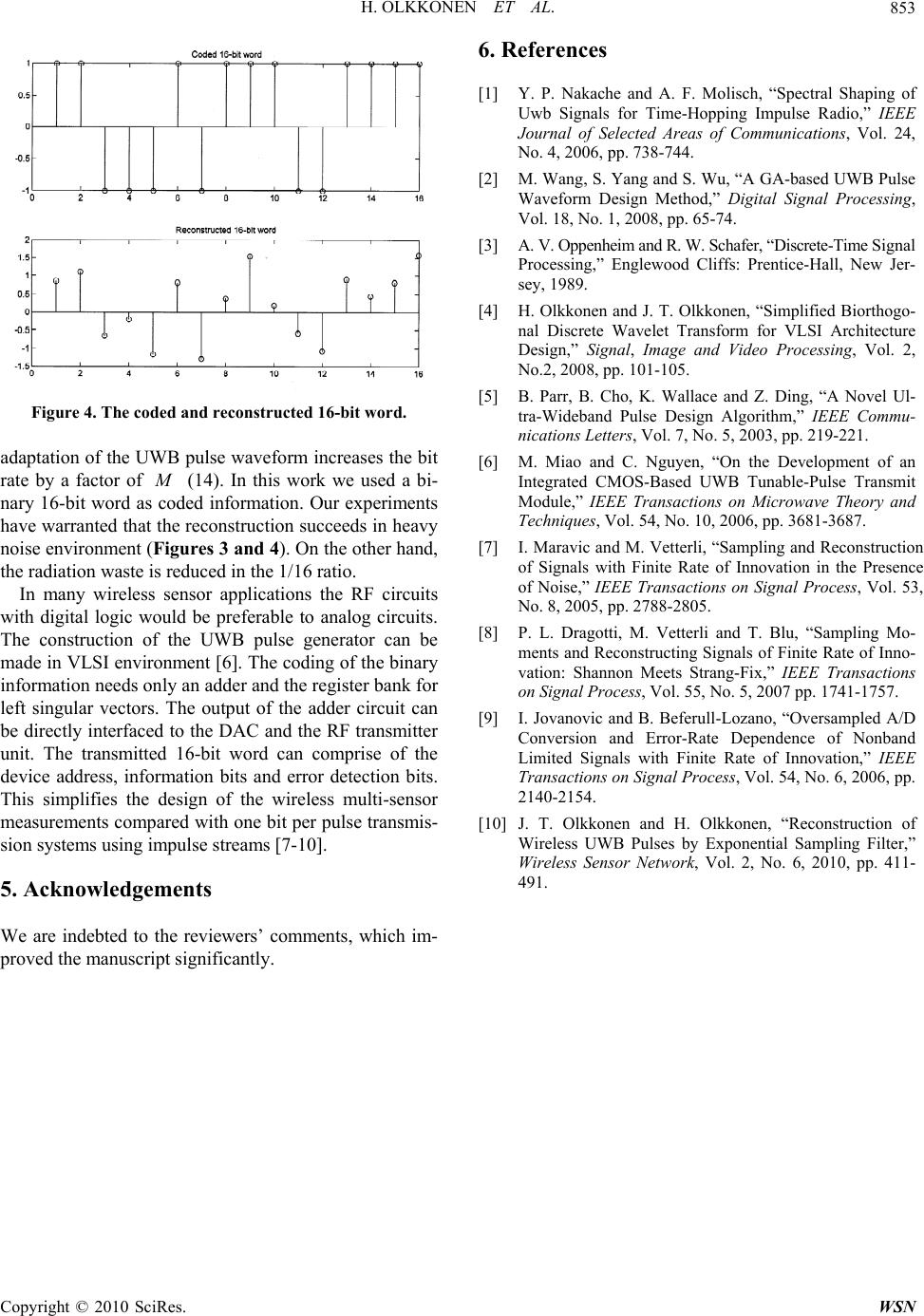 H. OLKKONEN ET AL. Copyright © 2010 SciRes. WSN 853 Figure 4. The coded and reconstructed 16-bit word. adaptation of the UWB pulse waveform increases the bit rate by a factor of M (14). In this work we used a bi- nary 16-bit word as coded information. Our experiments have warranted that the reconstruction succeeds in heavy noise environment (Figures 3 and 4). On the other hand, the radiation waste is reduced in the 1/16 ratio. In many wireless sensor applications the RF circuits with digital logic would be preferable to analog circuits. The construction of the UWB pulse generator can be made in VLSI environment [6]. The coding of the binary information needs only an adder and the register bank for left singular vectors. The output of the adder circuit can be directly interfaced to the DAC and the RF transmitter unit. The transmitted 16-bit word can comprise of the device address, information bits and error detection bits. This simplifies the design of the wireless multi-sensor measurements compared with one bit per pulse transmis- sion systems using impulse streams [7-10]. 5. Acknowledgements We are indebted to the reviewers’ comments, which im- proved the manuscript significantly. 6. References [1] Y. P. Nakache and A. F. Molisch, “Spectral Shaping of Uwb Signals for Time-Hopping Impulse Radio,” IEEE Journal of Selected Areas of Communications, Vol. 24, No. 4, 2006, pp. 738-744. [2] M. Wang, S. Yang and S. Wu, “A GA-based UWB Pulse Waveform Design Method,” Digital Signal Processing, Vol. 18, No. 1, 2008, pp. 65-74. [3] A. V. Oppenheim and R. W. Schafer, “Discrete-Time Signal Processing,” Englewood Cliffs: Prentice-Hall, New Jer- sey, 1989. [4] H. Olkkonen and J. T. Olkkonen, “Simplified Biorthogo- nal Discrete Wavelet Transform for VLSI Architecture Design,” Signal, Image and Video Processing, Vol. 2, No.2, 2008, pp. 101-105. [5] B. Parr, B. Cho, K. Wallace and Z. Ding, “A Novel Ul- tra-Wideband Pulse Design Algorithm,” IEEE Commu- nications Letters, Vol. 7, No. 5, 2003, pp. 219-221. [6] M. Miao and C. Nguyen, “On the Development of an Integrated CMOS-Based UWB Tunable-Pulse Transmit Module,” IEEE Transactions on Microwave Theory and Techniques, Vol. 54, No. 10, 2006, pp. 3681-3687. [7] I. Maravic and M. Vetterli, “Sampling and Reconstruction of Signals with Finite Rate of Innovation in the Presence of Noise,” IEEE Transactions on Signal Process, Vol. 53, No. 8, 2005, pp. 2788-2805. [8] P. L. Dragotti, M. Vetterli and T. Blu, “Sampling Mo- ments and Reconstructing Signals of Finite Rate of Inno- vation: Shannon Meets Strang-Fix,” IEEE Transactions on Signal Process, Vol. 55, No. 5, 2007 pp. 1741-1757. [9] I. Jovanovic and B. Beferull-Lozano, “Oversampled A/D Conversion and Error-Rate Dependence of Nonband Limited Signals with Finite Rate of Innovation,” IEEE Transactions on Signal Process, Vol. 54, No. 6, 2006, pp. 2140-2154. [10] J. T. Olkkonen and H. Olkkonen, “Reconstruction of Wireless UWB Pulses by Exponential Sampling Filter,” Wireless Sensor Network, Vol. 2, No. 6, 2010, pp. 411- 491. |