Paper Menu >>
Journal Menu >>
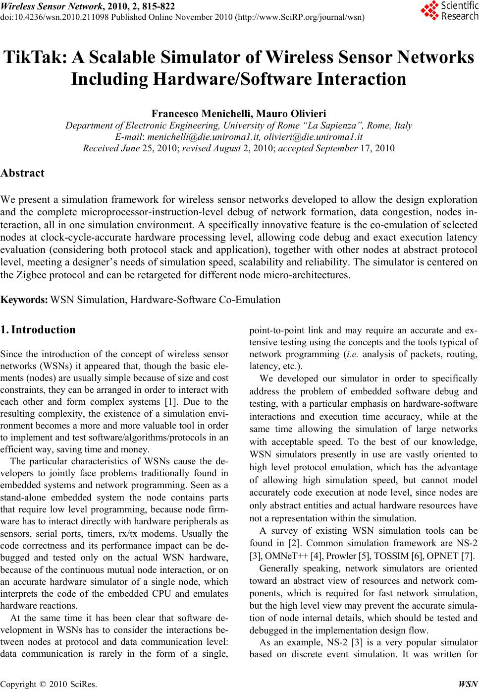 Wireless Sensor Network, 2010, 2, 815-822 doi:10.4236/wsn.2010.211098 Published Online November 2010 (http://www.SciRP.org/journal/wsn) Copyright © 2010 SciRes. WSN TikTak: A Scalable Simulator of Wireless Sensor Networks Including Hardware/Software Interaction Francesco Menichelli, Mauro Olivieri Department of Electronic Engineering, University of Rome “La Sapienza”, Rome, Italy E-mail: menichelli@die.uniroma1.it, olivieri@die.uniroma1.it Received June 25, 2010; revised August 2, 2010; accepted September 17, 2010 Abstract We present a simulation framework for wireless sensor networks developed to allow the design exploration and the complete microprocessor-instruction-level debug of network formation, data congestion, nodes in- teraction, all in one simulation environment. A specifically innovative feature is the co-emulation of selected nodes at clock-cycle-accurate hardware processing level, allowing code debug and exact execution latency evaluation (considering both protocol stack and application), together with other nodes at abstract protocol level, meeting a designer’s needs of simulation speed, scalability and reliability. The simulator is centered on the Zigbee protocol and can be retargeted for different node micro-architectures. Keywords: WSN Simulation, Hardware-Software Co-Emulation 1. Introduction Since the introduction of the concept of wireless sensor networks (WSNs) it appeared that, though the basic ele- ments (nodes) are usually simple because of size and cost constraints, they can be arranged in order to interact with each other and form complex systems [1]. Due to the resulting complexity, the existence of a simulation envi- ronment becomes a more and more valuable tool in order to implement and test software/algorithms/pro tocols in an efficient way, saving time and money. The particular characteristics of WSNs cause the de- velopers to jointly face problems traditionally found in embedded systems and network programming. Seen as a stand-alone embedded system the node contains parts that require low level programming, because node firm- ware has to interact directly with hardware peripherals as sensors, serial ports, timers, rx/tx modems. Usually the code correctness and its performance impact can be de- bugged and tested only on the actual WSN hardware, because of the continuous mutual node interaction, or on an accurate hardware simulator of a single node, which interprets the code of the embedded CPU and emulates hardware reactions. At the same time it has been clear that software de- velopment in WSNs has to consider the interactions be- tween nodes at protocol and data communication level: data communication is rarely in the form of a single, point-to-point link and may require an accurate and ex- tensive testing using th e concepts and the tools typical of network programming (i.e. analysis of packets, routing, latency, etc.). We developed our simulator in order to specifically address the problem of embedded software debug and testing, with a particular emphasis on hardware-software interactions and execution time accuracy, while at the same time allowing the simulation of large networks with acceptable speed. To the best of our knowledge, WSN simulators presently in use are vastly oriented to high level protocol emulation, which has the advantage of allowing high simulation speed, but cannot model accurately code execution at node level, since nodes are only abstract entities and actual h ardware resources have not a representation within the simulation. A survey of existing WSN simulation tools can be found in [2]. Common simulation framework are NS-2 [3], OMNeT++ [4], Prowler [5], TOSSIM [6], OPNET [7]. Generally speaking, network simulators are oriented toward an abstract view of resources and network com- ponents, which is required for fast network simulation, but the high level view may prevent the accurate simula- tion of node internal details, which should be tested and debugged in the implementation design flow. As an example, NS-2 [3] is a very popular simulator based on discrete event simulation. It was written for 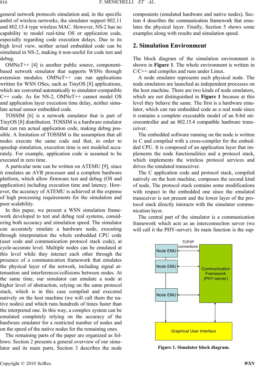 F. MENICHELLI ET AL. Copyright © 2010 SciRes. WSN 816 general network protocols simulation and, in the specific ambit of wireless networks, the simulator support 802.11 and 802.15.4 type wireless MAC. However, NS-2 has no capability to model real-time OS or application code, especially regarding code execution delays. Due to its high level view, neither actual embedded code can be simulated in NS-2, making it non-useful for code test and debug. OMNeT++ [4] is another public source, component- based network simulator that supports WSNs through extension modules. OMNeT++ can run applications written for WSN OSes, such as TinyOS [8] applications, which are converted au tomatically to simulato r- c om pa t ib l e C++ code. As for NS-2, OMNeT++ cannot model OS and application layer ex ecution time delay, neither simu- late actual sensor embedded code. TOSSIM [6] is a network simulator that is part of TinyOS [8] distribution. TOSSIM is a hardware emulator that can run actual application code, making debug pos- sible. A limitation of TOSSIM is the assumption that all nodes execute the same code and that, in order to speedup simulation, ex ecution time is not modeled accu- rately. For example, application code is assumed to be executed in zero time. A particular note can b e written on ATEMU [9], since it emulates an AVR processor and a complete hardware platform, which allow firmware test and debug (OS and application) including execution time and latency. How- ever, the accuracy of ATEMU is achieved at the expense of high processing requirements for the simulation and poor scalability. In this paper, we present a WSN simulation frame- work developed to test and debug real systems, consid- ering both accuracy and simulation speed. The simulator can accurately emulate a hardware node, executing through interpretation the whole embedded CPU code (user code and communication protocol stack code), at cycle-accurate level. Multiple nodes can be emulated at this level while they interact each other through the presence of a communication framework that emulates the physical layer of the network, including signal at- tenuation and interferences/collisions between nodes. At the same time, our simulator can emulate a node at higher level of abstraction, relying on the same protocol stack, which is in this case compiled and executed natively on the host machine (we will call them the na- tive nodes) and which runs hundreds of times faster than the interpreted one. In this way, a complex system can be emulated completely relying on the accuracy of the hardware emulator for a restricted number of nodes and on the speed of the native nodes for the remaining ones. The remaining parts of the paper are organized as fol- lows: Section 2 presents a general overview of our simu- lator and its main parts, Section 3 describes the node components (emulated hardware and native nodes), Sec- tion 4 describes the communication framework that emu- lates the physical layer. Finally, Section 5 shows some examples along with results and simulation speed. 2. Simulation Environment The block diagram of the simulation environment is shown in Figure 1. The whole environment is written in C/C++ and compiles and runs un der Linux. A node emulator represents each physical node. The node emulators are launched as independent processes on the host machine. There are two kinds of node emulators, which are not distinguished in Figure 1 because at this level they behave the same. The first is a hardware emu- lator, which can run embedded code as a real node since it contains a complete executable model of an 8-bit mi- crocontroller and an 802.15.4 compatible hardware trans- ceiver. The embedded software running on the nod e is written in C and compiled with a cross-compiler for the embed- ded CPU. It is composed of an application layer that im- plements the node functionalities and a protocol stack, which implements the wireless protocol services and drives the emulated transceiver. The C application code and protocol stack, compiled natively on the host machine, composes the second kind of node. The protocol stack contains some modifications with respect to the embedded one since the emulated transceiver is not present and the lower layer of the pro- tocol stack directly interacts with the simulator commu- nication layer. The central part of the simulator is a communication framework which acts as an interconnection server (we will call it the PHY-server). Its main function is the sup - Node EMU Comm un ica tio n Framework (PHY-server) TCP/IP connections Graphical User Interface Node EMU Node EMU Figure 1. Simulator block diagram. 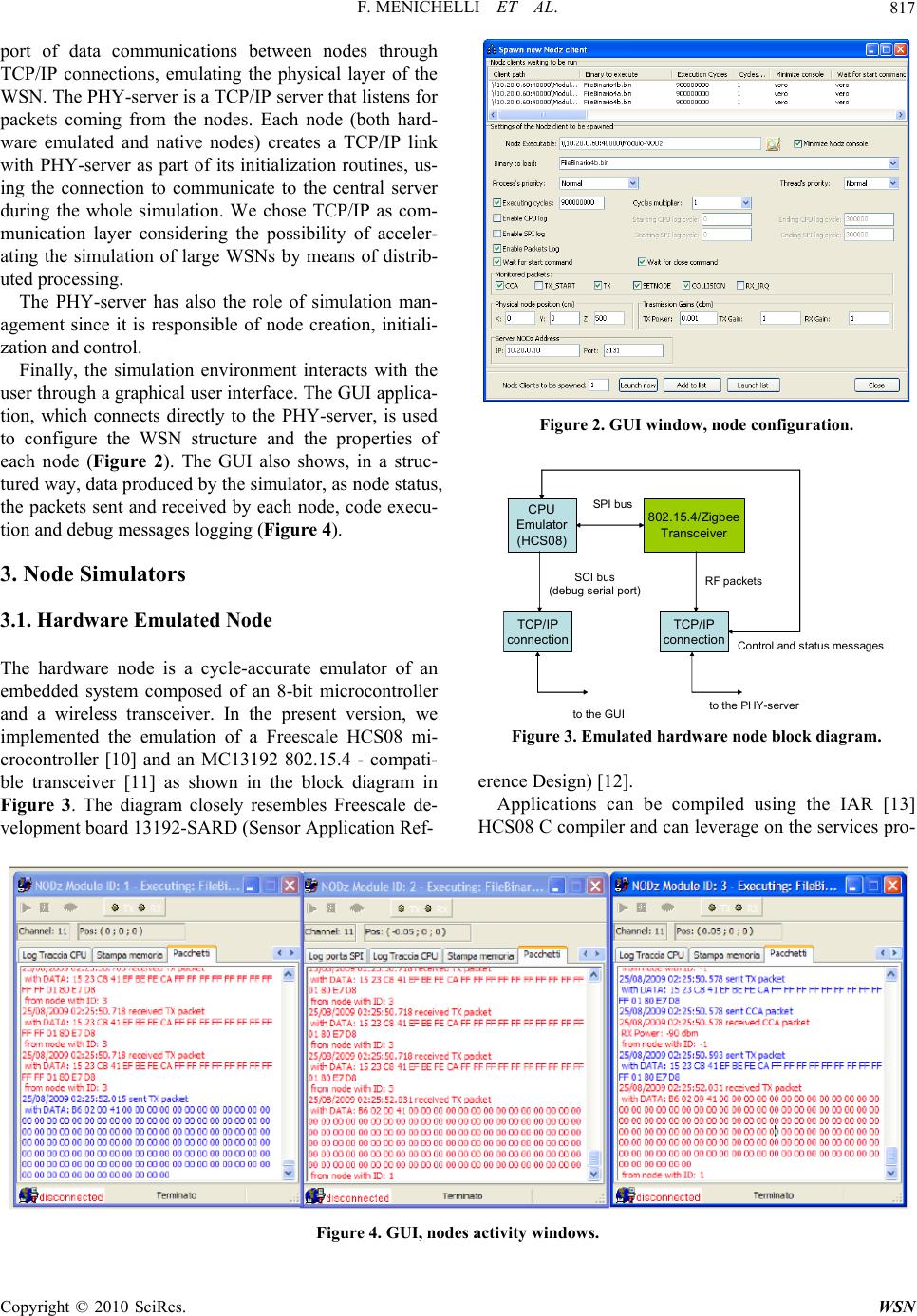 F. MENICHELLI ET AL. Copyright © 2010 SciRes. WSN 817 port of data communications between nodes through TCP/IP connections, emulating the physical layer of the WSN. The PHY-server is a TCP/IP server that listens for packets coming from the nodes. Each node (both hard- ware emulated and native nodes) creates a TCP/IP link with PHY-server as part of its initialization routines, us- ing the connection to communicate to the central server during the whole simulation. We chose TCP/IP as com- munication layer considering the possibility of acceler- ating the simulation of large WSNs by means of distrib- uted processing. The PHY-server has also the role of simulation man- agement since it is responsible of node creation, initiali- zation and control. Finally, the simulation environment interacts with the user through a graphical user interface. The GUI applica- tion, which connects directly to the PHY-server, is used to configure the WSN structure and the properties of each node (Figure 2). The GUI also shows, in a struc- tured way, data produced by the simulator, as node status, the packets sent and received by each node, code execu- tion and debug messages logging (Figure 4). 3. Node Simulators 3.1. Hardware Emulated Node The hardware node is a cycle-accurate emulator of an embedded system composed of an 8-bit microcontroller and a wireless transceiver. In the present version, we implemented the emulation of a Freescale HCS08 mi- crocontroller [10] and an MC13192 802.15.4 - compati- ble transceiver [11] as shown in the block diagram in Figure 3. The diagram closely resembles Freescale de- velopment board 13192-SARD (Sensor Application Ref- Figure 2. GUI window, node configur ation. CPU Emulator (HCS 0 8 ) 802.15.4/Zigbee Tra nsc eiver SPI bus TCP/I P connection SCI bus (debugserial port) TCP/IP connection RF packets tothe GUItothe PHY-server Controland status messages Figure 3. Emulated hardware node block diagr am. erence Design) [12]. Applications can be compiled using the IAR [13] HCS08 C compiler and can leverage on the services pro- Figure 4. GUI, nodes activity windows. 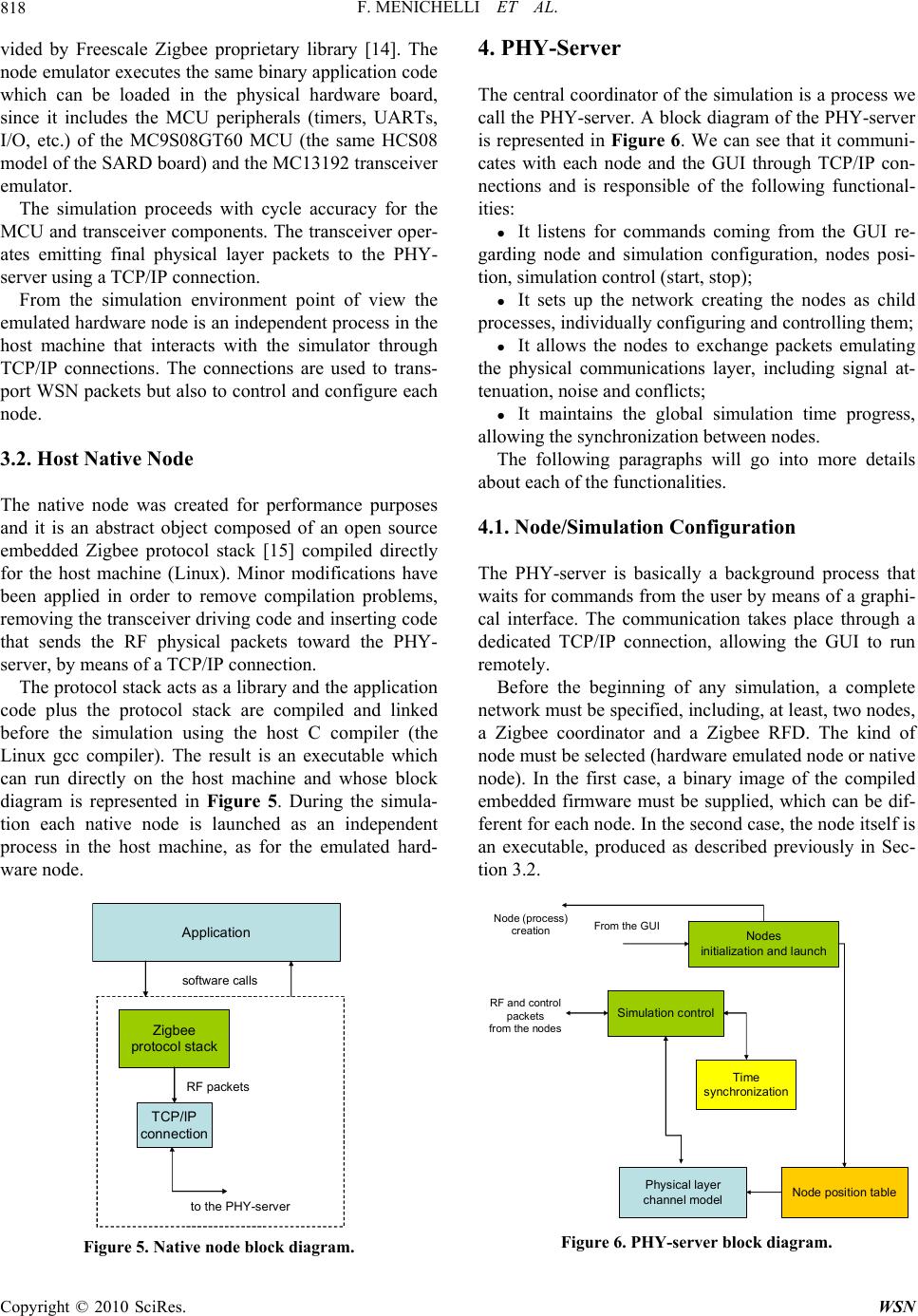 F. MENICHELLI ET AL. Copyright © 2010 SciRes. WSN 818 vided by Freescale Zigbee proprietary library [14]. The node emulator executes the same binary application code which can be loaded in the physical hardware board, since it includes the MCU peripherals (timers, UARTs, I/O, etc.) of the MC9S08GT60 MCU (the same HCS08 model of the SARD board) an d the MC13192 tr ansceiv er emulator. The simulation proceeds with cycle accuracy for the MCU and transceiver components. The transceiver oper- ates emitting final physical layer packets to the PHY- server using a TCP/ IP co nnection. From the simulation environment point of view the emulated hardware node is an independent process in the host machine that interacts with the simulator through TCP/IP connections. The connections are used to trans- port WSN packets but also to control and configure each node. 3.2. Host Native Node The native node was created for performance purposes and it is an abstract object composed of an open source embedded Zigbee protocol stack [15] compiled directly for the host machine (Linux). Minor modifications have been applied in order to remove compilation problems, removing the transceiver driving code and inserting code that sends the RF physical packets toward the PHY- server, by means of a TCP/IP connection. The protocol stack acts as a library and the application code plus the protocol stack are compiled and linked before the simulation using the host C compiler (the Linux gcc compiler). The result is an executable which can run directly on the host machine and whose block diagram is represented in Figure 5. During the simula- tion each native node is launched as an independent process in the host machine, as for the emulated hard- ware node. Ap p lica t io n Zigbee protocol stack TCP/IP connection RF packets tothe PHY-server software calls Figure 5. Native node block diagram. 4. PHY-Server The central coordinator of the simulation is a process we call the PHY-server. A block diagram of the PHY-server is represented in Figure 6. We can see that it communi- cates with each node and the GUI through TCP/IP con- nections and is responsible of the following functional- ities: It listens for commands coming from the GUI re- garding node and simulation configuration, nodes posi- tion, sim ul a ti on control (start, stop); It sets up the network creating the nodes as child processes, individually configuring and controlling them; It allows the nodes to exchange packets emulating the physical communications layer, including signal at- tenuation, noise and conflicts; It maintains the global simulation time progress, allowing the synchronization between nodes. The following paragraphs will go into more details about each of the functionalities. 4.1. Node/Simulation Configuration The PHY-server is basically a background process that waits for commands from the user by means of a graphi- cal interface. The communication takes place through a dedicated TCP/IP connection, allowing the GUI to run remotely. Before the beginning of any simulation, a complete network must be specified, including, at least, two nodes, a Zigbee coordinator and a Zigbee RFD. The kind of node must be selected (hardware emulated node or native node). In the first case, a binary image of the compiled embedded firmware must be supplied, which can be dif- ferent for each node. In the second case, the node itself is an executable, produced as described previously in Sec- tion 3.2. Physica l layer channel model Sim ulati on contr ol RF and control packets from the nodes From the GUI Time s ynchr onizat ion Node position table Nodes initialization and launch Node (proc ess) creation Figure 6. PHY-server block diagram.  F. MENICHELLI ET AL. Copyright © 2010 SciRes. WSN 819 Further information that must be supplied regards the data needed in the emulation of the physical communica- tion layer as node position, transmission power, receiver signal thre shold, backg round noise . Finally, optional parameters to be specified are the set of tracing data that should be sent to the GUI. The pa- rameters must be specified essentially for simulation time speedup, since the network simulation can include many details from the higher abstraction level (e.g. per node packet activity) to lo wer abstraction level (per node physical layer activity, including channel monitoring) and the details of the hardware emulated nodes (e.g. in- structions trace, CPU registers state, etc.). When the PHY-server receives a complete set of data for a node it proceeds with its creation and its inclusion in the network. 4.2. Network Setup The network setup functionalities regard the creation of each node, its configuration/initialization and control. The PHY-server launches each new node as a process in the same host machine or on a different host machine, sending also the configuration (i.e. the firmware for the hardware-emulated node) to the node. As part of its ini- tialization, each node estab lishes a TCP/IP connection to the PHY-server, which will be used for the emulation of the physical communication layer. Each node also estab- lishes a direct connection with the GUI, which is used to send node activity information. In case of the hardware -emulated node, the information can include hardware details as instructions log and processor/peripheral state as usually required by an embedded system software test/ debug session. 4.3. Emulation of the Physical Communication Layer The main functionality of the PHY-server is the emula- tion of the physical radio communication during the network simulation. The PHY-server maintains a list of the instantiated nodes, including their positions. During the simulation, it computes the state of the received sig- nal for each node including the presence of a radio signal coming from a transmitting node, background noise, and interference of other transmitting nodes that are colliding with the first. The nodes interact with the PHY-server sending both control and data packets. Control packets at the physical communication layer emulation are used to send request from the receiver (e.g. when a node turns on the receiver to inspect if the channel is occupied before transmitting) while data packets are used to send the actual physical packets to the PHY-server. When the PHY-server re- ceives a control packet it always replies with the re- quested information (e.g. channel signal strength used by the node receiver to determine if the channel is free or busy). The radio communication emulation is centralized in the PHY-server, which means that the nodes will never exchange packets directly, but only through the PHY -server. This centralized policy allows the PHY-server to log data packets for network traffic monitoring and, in case, to modify data packets (e.g. inserting controlled errors at bit level) to emulate noise and interference presence. Effectively, when the PHY-server receives a data pac ke t (i.e. a physical packet sent by a transmitter) it bro adcasts the packet to all nodes. In order to test network/firmware response/robustness to packet errors, the real radio channel characteristics are emulated applying formulas for signal attenuation, background noise, interference by other nodes and computing the bit error rate for each receiver. The packets are then modified inserting random errors accordingly. In the present version of the simulator, signal attenua- tion and interference are computed applying a simple free-space law, but, due to the modularity of the function, the computation could be modified or obtained from an external EM field simulator. 4.4. Simulation Time Synchronization A critical aspect of the simulation is time accuracy and synchronization between simulated nodes. The PHY -server provides for the generation of a global simulation clock. Since a clock accurate simulation would induce excessive overhead, each node is granted a variable-length time slot, in the order of a fraction of milliseconds of simulated time. During the time slot the node can run freely, advancing its internal state. The generation of external events, such as packet transmission and RF chan- nel monitoring causes the time slot to break prematurely and leave the control to the PHY-server. Ideally, shorter time slots should be preferred since they generate more accurate simulations, but accuracy has a trade off with simulation speed because of the overhead of the start- stop procedure, which gets more and more frequent. 5. Examples and Results 5.1. Comparison with a Physical Zigbee Network In this Section, we show a comparison between the re- sults obtained by our simulator and the results obtained using an actual physical Zigbee network. The nodes for the physical network are built around a Texas Instru- ments CC2431 Zigbee transceiver [16] using the open  F. MENICHELLI ET AL. Copyright © 2010 SciRes. WSN 820 source Zigbee stack [15] (the same used in the simula- tor). The configurations used are showed in Figure 7; in both cases the RFD sends a 10 K bytes data block to the Zigbee coordinator, using a direct single-hop connection (configuration I ) o r thro u gh a router (configuration II). To further increment the exploration space, the packet payload size is set to three values (93, 43 and 20 bytes). The experiment is supposed to be performed in absence of interference (no packet losses in the simulator and very low losses in the real case). Table 1 and Table 2 show the results. The through- puts obtained by the simulator are in substantial accor- dance with the real case, showing a slightly higher throughput due to the complete absence packet losses in the simulator. As expected, throughput decreases when packet payload size is reduced due to the overheads of packet headers and transmission interval guards between packets. 5.2. Simulation Time and Numbers of Nodes In this section we present the results on simulation time considering a variable number of nod es, both in terms of execution time (real time) and simulated time. The net- work is composed by a coordinator, a RFD node and a variable number of routers between them. The RFD sends small packets to the coordinator (ping) and wait for a reply (pong). The simulated time is maintained con- stant to approximately 20 s. The results of the simulation are shown in Table 3, where 0 #routers means a direct connection between the RFD and the coordinator nodes. The traffic reported is Figure 7. Configuration I (left) and configuration II (right). Table 1. Measured vs. simulated throughput in configura- tion I. Payload Bytes Data Kbytes Measured throughput (Kbits/s) Simulated throughput (Kbits/s) 93 10 83 90 43 10 50 56 20 10 26 28 Table 2. Measured vs. simulated throughput in configura- tion II. Payload Bytes Data Kbytes Measured throughput (Kbits/s) Simulated throughput (Kbits/s) 93 10 43 49 43 10 26 30 20 10 14 15 Table 3. Execution time with 32us time slots. # routers Execution time (s) Simulated time (s) Traffic (MB) 0 80.24 20 194.99 1 125.93 20 195.04 2 167.61 20 195.43 3 207.83 20 195.32 the total traffic generated by the PHY-simulator on the host platform, and is composed by control, synchroniza- tion and data messages. As exposed in Section 4.4, execu- tion time can be reduced by increasing the granularity of the synchronization events between the node simulators the central PHY-server. As an example, the time slots are increased from the 32us used in the simulation in Table 3 to 128us, and the results are shown in Table 4. We can notice about a 3.6x speedup from the previous results and an analogous reduction in the traffic generated. The two other tests we report are based on an increas- ing number of RFD nodes that want to communicate directly with the coordinator. The first one is a traf- fic-intense application, in which each node needs to transfer a block of 13 K bytes of data to the coordinator using the maximum (87 bytes) packet payload size. The network and the simulator are particularly stressed be- cause of the high network activity. Table 5 shows the results. Since increasing the num- ber of nodes increases the total size of data to be trans- ferred, simulated time gets longer and data throughput decreases due to network congestion and contention as shown by the packet error rate (PER) column. Figure 8 shows graphically the dependence of execution time from the number of nodes. Remarking that this is a high demanding test, we can see a change in the curve slope, which generally indicates resource saturation on the Table 4. Execution time with 128us time slots. # routers Execution time (s) Simulated time (s) Traffic (MB) 0 22.15 20 49.35 1 33.68 20 49.37 2 45.42 20 49.40 3 58.73 20 49.55  F. MENICHELLI ET AL. Copyright © 2010 SciRes. WSN 821 Table 5. Simulation results – traffic-intense application. # RFD nodes execution time (s) simulated time (s) Throughput Kbits/s PER % 1 15 1.5 70 0 2 40 2 52 2.5 3 100 2.5 42 4 4 150 3 35 6 5 200 3.5 30 7.5 6 350 4.5 23 10.5 7 550 5 21 11.5 8 1300 6.5 16 16 9 2100 7.5 14 19 10 2900 8.5 12 22 11 3700 9.5 11 23 12 4500 11 9.5 24 13 5300 12 8.5 25.5 14 6100 13 8 27 0 1000 2000 3000 4000 5000 6000 7000 051015 # RFD node s Execution time (s) Figure 8. Execution time vs. # of RFD nodes. simulating host machine (a standard desktop, 2 G Byte RAM, PC). Figure 9 and Figure 10 show the throughput and the Packet Error Rate in relation to the number of nodes. We report the test using three different packet payload sizes (87 bytes, 44 bytes and 22 bytes). The second test is an application based on a set of nodes that send low traffic volumes (a case where the Zigbee protocol is more suited). Figure 11 shows the transmission latency (the time difference between when a source node sends a packet and when it receives a reply from the destination) considering a variable number of nodes for the worst and average case. Since the network is not saturated, increasing the number of nodes does not increase significantly the average latency. Secondly, the same test is repeated in presence of in- terfering nodes (Zigbee nodes that send data using the same channel). Figure 12 and Figure 13 report the re- sults. On the x-axis is the number of interfering nodes, Figure 12 regards the presence of a single RFD trans- mitting node while Figure 13 regards the presence of 10 RFD transmitting nodes (in addition to the interfering nodes). We can notice a linear dependence of the average latency with the number of interfering nodes. Finally, Table 6 reports a resume of the comparison between the characteristics of our simulator and other 0 10 20 30 40 50 60 70 80 0123456789101112131415 # RFD nodes Throughput (Kbit/s) 87bytespayload 22bytespayload 44bytespayload Figure 9. Throughput vs. # RFD node s. 0 5 10 15 20 25 30 0510 15 # RF D n o des PER (% ) 22bytespayload 87bytespayload 44bytespayload Figure 10. Packet error rate vs. # RFD nodes. 0 0.05 0.1 0.15 0.2 0.25 0246810121416 # RFD nodes Late nc y (s) worstcase average Figure 11. Transmission latency vs. # RFD nodes. 0 0.02 0.04 0.06 0.08 0.1 0.12 0.14 0.16 0.18 0123456 # in terferin g RFD n od es Late n c y (s ) worstcase average Figure 12. Transmission latency vs. # RFD interfering nodes (1 RFD transmitter). WSN simulators presented in Section 1 6. Conclusions We reported the structure and the results obtained by the  F. MENICHELLI ET AL. Copyright © 2010 SciRes. WSN 822 Table 6. Comparison between simulators. Simulator Supported network Radio model OS and SW execu- tion time modelingHW/SW interaction modeling Scalability NS-2 802.11, 802.15.4, DSDV, DSR, TORA, AODV shadowing, 2-ray ground, free space no no Yes OMNET++ 802.11 free space, 2-ray ground no no Yes TOSSIM CSMA probabilistic bit errorno no Yes ATEMU CSMA free space yes yes No TikTak Zigbee free space, probabilistic bit erroryes yes Yes 0 0.05 0.1 0.15 0.2 0.25 0.3 0123456 #int erf erin gRFDnode s La ten c y (s) worstcase average Figure 13. Transmission latency vs. # RFD interfering nodes (10 RFD transmitters). TikTak WSN simulator we have developed. The simula- tor is composed in a modular way, and nodes can be emulated at two levels of abstraction. The major charac- teristic is the ability to simulate the program and stack latency because of low-level hardware emulation of the nodes and to allow the test and debug of embedded codes as in final application. At the same time, emulation at protocol level allows to increase the simulation speed when timing accuracy is less stringent. The physical channel model is, at the moment, a free -space attenuation model, but the modularity allows the insertion of more elaborate models. 7. References [1] K. Romer and F. Mattern, “The Design Space of Wireless Sensor Networks,” Wireless Communications, IEEE, Vol. 11, No. 6, 2004, pp. 54-61. [2] M. Korkalainen, M. Sallinen, N. Karkkainen and P. Tukeva, “Survey of Wireless Sensor Networks Simulation Tools for Demanding Applications,” International conference on Net- working and Services, Valencia, Spain, 2009, pp. 102-106. [3] “The Network Simulator—ns-2,” Information Sciences In- stitute, University of Southern California, 2010. http://www. isi.edu/nsn am/ns [4] A. Varga and R. Hornig, “An Overview of the OMNeT++ Simulation Environment,” Simutools '08: Proceedings of the 1st International Conference on Simulation Tools and Techniques for Communications, Networks and Systems & Workshops, Marseille, France, 2008, pp. 1-10. [5] “Prowler network simulator,” Institute for Software Inte- grated Systems, Vanderbilt University, Nashville, Tennes- see, 2002. http://www.i sisva nde rbilt.edu/Projects/nest/prow- ler [6] P. Levis, N. Lee, M. Welsh and D. Culler, “TOSSIM: Ac- curate and Scalable Simulation of Entire Tinyos Applica- tions,” Proceedings of the 1st International Conference on Embedded Networked Sensor Systems, Los Angeles, CA, 2003, pp. 12 6-137. [7] “OPNET Network Simulator,” OPNET Technologies Inc, 2010. http://www.opnet.com [8] P. Levis, S. Madden, J. Polastre, R. Szewczyk, K. White- house, A. Woo, D. Gay, J. Hill, M. Welsh, E. Brewer and D. Culler, “Tinyos: An Operating System for Sensor Net- works,” in Ambient Intelligence, Springe r, New York, 2005, pp. 115-148. [9] J. Polley, D. Blazakis, J. Mcgee, D. Rusk and J. S. Baras, “ATEMU: A Fine-Grained Sensor Network Simulator,” First Annual IEE E Communications Society Confe rence on Sensor and Ad Hoc Communications and Networks (IEEE SECON 2004), Santa Clara, CA, 2004, pp. 145-152. [10] HCS8 family microcontroller, Freescale semiconductor, http: //www.freescale.com [11] MC13192: 2.4 GHz, Low Power Transceiver for 802.15.4, Freescale semiconductor, http://www.freescale.com [12] MC13192 Evaluation Board Reference Manual, Freescale semiconductor, http://www.freescale.com [13] IAR Embedded Workbench® for S08, IAR Systems, http: //www.iar.com [14] “802.15.4 MAC PHY Software User’s Guide,” Freescale semiconductor, document number 802154MPSUG, 2005. [15] R. B. Reese, “A Zigbee-Subset/IEEE 802.15.4 Multi-plat- form Protocol Stack V0.2.6,” 2007. http://www.ece msstate. edu/~reese/msstatePAN/ [16] “System-on-Chip for 2.4 GHz ZigBee(TM)/IEEE 802.15.4 with Location Engine,” http://focus.ti.com/docs/prod/fo- lders/print/cc2431.html |